Body and Trim NISSAN TERRANO 2004 Service Repair Manual
[x] Cancel search | Manufacturer: NISSAN, Model Year: 2004, Model line: TERRANO, Model: NISSAN TERRANO 2004Pages: 1833, PDF Size: 53.42 MB
Page 2 of 1833
Edition: February 2004
Release: February 2004 (01)
Publication No.: SM4E00-1R20E0E
Reference No.: 7711347141
GENERAL INFORMATIONGI
MAINTENANCEMA
ENGINE MECHANICALEM
ENGINE LUBRICATION &
COOLING SYSTEMSLC
ENGINE CONTROL SYSTEMEC
ACCELERATOR CONTROL,
FUEL & EXHAUST SYSTEMFE
CLUTCHCL
MANUAL TRANSMISSIONMT
AUTOMATIC TRANSMISSIONAT
TRANSFERTF
PROPELLER SHAFT &
DIFFERENTIAL CARRIERPD
FRONT AXLE & FRONT SUSPENSIONFA
REAR AXLE & REAR SUSPENSIONRA
BRAKE SYSTEMBR
STEERING SYSTEMST
RESTRAINT SYSTEMRS
BODY & TRIMBT
HEATER & AIR CONDITIONERHA
STARTING & CHARGING SYSTEMSSC
ELECTRICAL SYSTEMEL
ALPHABETICAL INDEXIDX
TERRANO
MODEL R20 SERIES
NISSAN EUROPE S.A.S.
2004 NISSAN EUROPE S.A.S.
Produced in The Netherlands
Not to be reproduced in whole or in part
without the prior written permission of
Nissan Europe S.A.S., Paris, France.
QUICK REFERENCE INDEX
http://vnx.su/
Page 44 of 1833
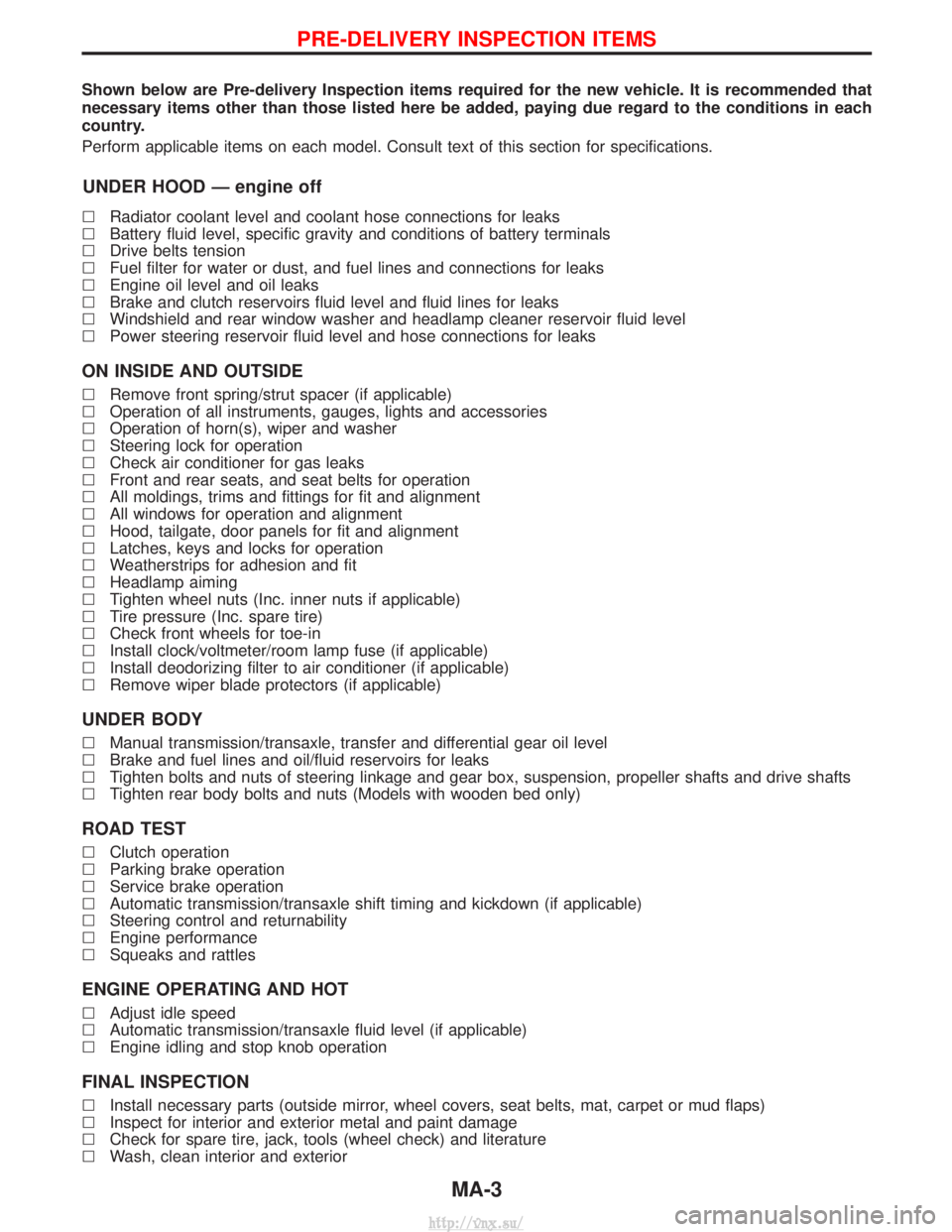
Shown below are Pre-delivery Inspection items required for the new vehicle. It is recommended that
necessary items other than those listed here be added, paying due regard to the conditions in each
country.
Perform applicable items on each model. Consult text of this section for specifications.
UNDER HOOD Ð engine off
lRadiator coolant level and coolant hose connections for leaks
l Battery fluid level, specific gravity and conditions of battery terminals
l Drive belts tension
l Fuel filter for water or dust, and fuel lines and connections for leaks
l Engine oil level and oil leaks
l Brake and clutch reservoirs fluid level and fluid lines for leaks
l Windshield and rear window washer and headlamp cleaner reservoir fluid level
l Power steering reservoir fluid level and hose connections for leaks
ON INSIDE AND OUTSIDE
lRemove front spring/strut spacer (if applicable)
l Operation of all instruments, gauges, lights and accessories
l Operation of horn(s), wiper and washer
l Steering lock for operation
l Check air conditioner for gas leaks
l Front and rear seats, and seat belts for operation
l All moldings, trims and fittings for fit and alignment
l All windows for operation and alignment
l Hood, tailgate, door panels for fit and alignment
l Latches, keys and locks for operation
l Weatherstrips for adhesion and fit
l Headlamp aiming
l Tighten wheel nuts (Inc. inner nuts if applicable)
l Tire pressure (Inc. spare tire)
l Check front wheels for toe-in
l Install clock/voltmeter/room lamp fuse (if applicable)
l Install deodorizing filter to air conditioner (if applicable)
l Remove wiper blade protectors (if applicable)
UNDER BODY
lManual transmission/transaxle, transfer and differential gear oil level
l Brake and fuel lines and oil/fluid reservoirs for leaks
l Tighten bolts and nuts of steering linkage and gear box, suspension, propeller shafts and drive shafts
l Tighten rear body bolts and nuts (Models with wooden bed only)
ROAD TEST
lClutch operation
l Parking brake operation
l Service brake operation
l Automatic transmission/transaxle shift timing and kickdown (if applicable)
l Steering control and returnability
l Engine performance
l Squeaks and rattles
ENGINE OPERATING AND HOT
lAdjust idle speed
l Automatic transmission/transaxle fluid level (if applicable)
l Engine idling and stop knob operation
FINAL INSPECTION
lInstall necessary parts (outside mirror, wheel covers, seat belts, mat, carpet or mud flaps)
l Inspect for interior and exterior metal and paint damage
l Check for spare tire, jack, tools (wheel check) and literature
l Wash, clean interior and exterior
PRE-DELIVERY INSPECTION ITEMS
MA-3
http://vnx.su/
Page 1338 of 1833
BODY & TRIM
SECTION
BT
CONTENTS
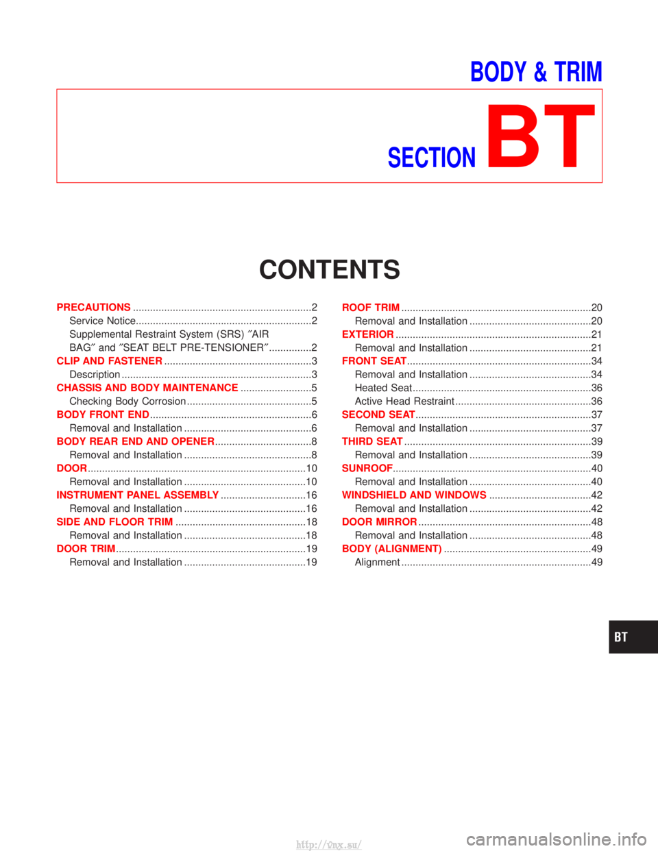
PRECAUTIONS ...............................................................2
Service Notice..............................................................2
Supplemental Restraint System (SRS) ²AIR
BAG² and²SEAT BELT PRE-TENSIONER² ...............2
CLIP AND FASTENER ....................................................3
Description ...................................................................3
CHASSIS AND BODY MAINTENANCE .........................5
Checking Body Corrosion ............................................5
BODY FRONT END .........................................................6
Removal and Installation .............................................6
BODY REAR END AND OPENER ..................................8
Removal and Installation .............................................8
DOOR ........................................................................\
.....10
Removal and Installation ...........................................10
INSTRUMENT PANEL ASSEMBLY ..............................16
Removal and Installation ...........................................16
SIDE AND FLOOR TRIM ..............................................18
Removal and Installation ...........................................18
DOOR TRIM ...................................................................19
Removal and Installation ...........................................19 ROOF TRIM
...................................................................20
Removal and Installation ...........................................20
EXTERIOR .....................................................................21
Removal and Installation ...........................................21
FRONT SEAT .................................................................34
Removal and Installation ...........................................34
Heated Seat ...............................................................36
Active Head Restraint ................................................36
SECOND SEAT ..............................................................37
Removal and Installation ...........................................37
THIRD SEAT ..................................................................39
Removal and Installation ...........................................39
SUNROOF ......................................................................40
Removal and Installation ...........................................40
WINDSHIELD AND WINDOWS ....................................42
Removal and Installation ...........................................42
DOOR MIRROR .............................................................48
Removal and Installation ...........................................48
BODY (ALIGNMENT) ....................................................49
Alignment ...................................................................49
http://vnx.su/
Page 1339 of 1833
Service Notice
IWhen removing or installing various parts, place a cloth or padding onto the vehicle body to prevent
scratches.
I Handle trim, molding, instruments, grille, etc. carefully during removing or installing. Be careful not to oil
or damage them.
I Apply sealing compound where necessary when installing parts.
I When applying sealing compound, be careful that the sealing compound does not protrude from parts.
I When replacing any metal parts (for example body outer panel, members, etc.), be sure to take rust pre-
vention measures.
Supplemental Restraint System (SRS) ªAIR
BAGº and ªSEAT BELT PRE-TENSIONERº
The Supplemental Restraint System such as ªAIR BAGº and ªSEAT BELT PRE-TENSIONERº used along with
a seat belt, helps to reduce the risk or severity of injury to the driver and front passenger for certain types of
collision. The SRS system composition which is available to NISSAN MODEL R20 is as follows (The compo-
sition varies according to the destination and optional equipment.):
IFor a frontal collision
The Supplemental Restraint System consists of driver air bag module (located in the center of the steer-
ing wheel), front passenger air bag module (located on the instrument panel on passenger side), front seat
belt pre-tensioners, a diagnosis sensor unit, warning lamp, wiring harness and spiral cable.
I For a side collision
The Supplemental Restraint System consists of front side air bag module (located in the outer side of front
seat), side air bag (satellite) sensor, diagnosis sensor unit (one of components of air bags for a frontal
collision), wiring harness, warning lamp (one of components of air bags for a frontal collision).
Information necessary to service the system safely is included in the RSsection of this Service Manual.
WARNING:
I To avoid rendering the SRS inoperative, which could increase the risk of personal injury or death
in the event of a collision which would result in air bag inflation, all maintenance should be per-
formed by an authorized NISSAN dealer.
I Improper maintenance, including incorrect removal and installation of the SRS, can lead to per-
sonal injury caused by unintentional activation of the system. For removal of Spiral Cable and Air
Bag Module, see the RS section.
I Do not use electrical test equipment on any circuit related to the SRS unless instructed to in this
Service Manual. Spiral cable and wiring harnesses covered with yellow insulation tape either just
before the harness connectors or for the complete harness are related to the SRS.
PRECAUTIONS
BT-2
http://vnx.su/
Page 1385 of 1833
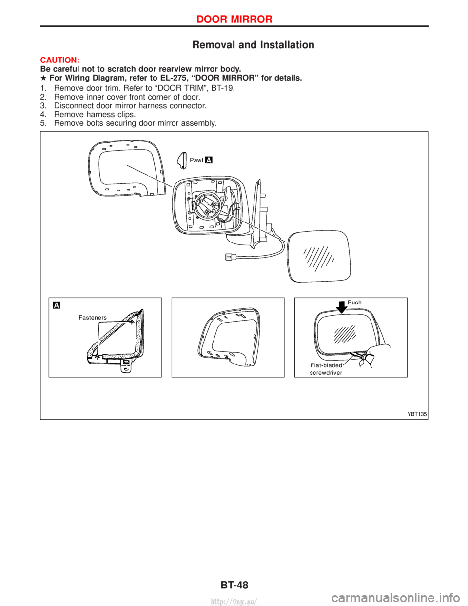
Removal and Installation
CAUTION:
Be careful not to scratch door rearview mirror body.
HFor Wiring Diagram, refer to EL-275, ªDOOR MIRRORº for details.
1. Remove door trim. Refer to ªDOOR TRIMº, BT-19.
2. Remove inner cover front corner of door.
3. Disconnect door mirror harness connector.
4. Remove harness clips.
5. Remove bolts securing door mirror assembly.
YBT135
DOOR MIRROR
BT-48
http://vnx.su/
Page 1827 of 1833
A
ABS (anti-lock brake system).........................BR-36
ABS - Wiring diagram ....................................BR-51
A/C air flow .......................................................HA-8
A/C compressor precaution..............................HA-5
A/C control operation (manual A/C) .................HA-6
A/C relay.........................................................HA-61
A/C symptom chart (manual A/C) ..................HA-36
A/C trouble diagnoses (manual A/C) .............HA-27
A/C, M - Wiring diagram ................................HA-43
ACC/SW - Wiring diagram ...........................EC-106
Accelerator control system ...........................FE-2, 5
Accelerator position sensor .........EC-130, 391, 394
Accelerator position switch ..................EC-392, 394
Accelerator switch (F/C) ...............................EC-104
Accelerator wire adjustment .............................FE-5
Accelerator work unit....................................EC-388
A/CCUT - Wiring diagram ............................EC-308
Air bag ..............................................................RS-8
Air bag disposal..............................................RS-22
Air bag precautions ...........................................GI-3
Air bleeding (hydraulic clutch) ..........................CL-6
Air bleeding for brake system ..........................BR-8
Air cleaner filter replacement ..............MA-5, 20, 24
Air conditioner cut control ..............EC-22, 334, 463
Air control cable adjustment...........................HA-62
Air flow meter - See Mass air flowsensor .................................................EC-88, 379
Alternator ........................................................SC-27
Angular tightening application..........................EM-3
Antenna.................................................EL-134, 150
Anti-lock brake system - See ABS .................BR-38
Anti-lock brake system - Wiring diagram .......................................................BR-51
APS - Wiring diagram ..................................EC-133
ASCD vacuum hose ......................................MA-40
A/T - Wiring diagram .........................................AT-7
A/T - Wiring diagram - AT - PNP/SW .............AT-89
A/T - Wiring diagram - AT - VSS A/T ..............AT-51
A/T control ....................................................EC-160
A/T diagnosis communication line ...............EC-160
A/T fluid checking ............................................AT-27
A/T fluid temperature sensor...........................AT-78
A/T mode switch..............................................AT-99
A/T self-diagnoses ....................................AT-14, 19
A/T Wiring diagram - AT - ENG SS ................AT-81
A/T Wiring diagram AT - BA/FTS ....................AT-77
A/T Wiring diagram AT - LPSV .......................AT-84
A/T Wiring diagram AT - OVRCSV .................AT-70
A/T Wiring diagram AT - SSV/A ......................AT-64
A/T Wiring diagram AT - SSV/B ......................AT-67
A/T Wiring diagram AT - TCV .........................AT-73
A/T Wiring diagram AT - TPS..........................AT-58
A/T Wiring diagram AT - VSSMTR .................AT-54
AT/C - Wiring diagram..................................EC-162
Audio .....................................................EL-134, 136
AUDIO - Wiring diagram ...............................EL-138 Audio and A/C control removal and
installation - See Instrument panel .............BT-16
Auto lock free running hub .............................FA-14
Automatic transmission number ......................GI-29
Axle housing (rear) ...........................................RA-8
B
Back Door .......................................................BT-14
Back door opener - See Back door ................BT-14
Back door trim.................................................BT-18
Back door window...........................................BT-43
Back-up lamp ..................................................EL-53
Back-up lamp switch (M/T) ........................MT-6, 10
BACK/L - Wiring diagram................................EL-53
Ball joint front axle ..........................................FA-36
Basic inspection .....................................EC-50, 361
Battery ..............................................................SC-3
Blower motor ..................................................HA-60
Blower resistor................................................HA-60
Body alignment ...............................................BT-49
BOOST - Wiring diagram .............................EC-222
Boring/horning cylinder block.........................EM-74
Brake booster .................................................BR-18
Brake fluid change ...........................................BR-5
Brake fluid level ...........................MA-17, 36, 40, 43
Brake fluid level and line check .......................BR-5
Brake hydraulic line......................................BR-5, 6
Brake inspection ..........................MA-36, 40, 41, 42
Brake lines and cables inspection.....MA-36, 40, 42
Brake lining wear temporary checking ....MA-36, 42
Brake master cylinder ....................................BR-17
Brake pedal ....................................................BR-14
Brake switch .................................................EC-423
BRK/SW - Wiring diagram ...........................EC-210
Bumper, front ....................................................BT-6
Bumper, rear .....................................................BT-8C
Camshaft ........................................................EM-30
Camshaft position sensor (PUMP)...............EC-166
Center case (Transfer) ......................................TF-9
CHARGE - Wiring diagram ............................SC-24
Charge air pressure sensor .........................EC-220
Charging system ............................................SC-23
Chassis and body maintenance ....................MA-36
CIGAR - Wiring diagram ...............................EL-123
Cigarette lighter.............................................EL-122
Circuit breaker.................................................EL-19
CKPS - Wiring diagram ................................EC-154
Clock .............................................................EL-122
CLOCK - Wiring diagram ..............................EL-124
Clutch cover ..............................................CL-11, 12
Clutch disc ......................................................CL-11
Clutch fluid level ......................................MA-17, 36
Clutch master cylinder ..................................CL-7, 8
Clutch pedal .............................................CL-3, 4, 5
ALPHABETICAL INDEX
IDX-2
http://vnx.su/
Page 1832 of 1833
T
Tachometer .....................................................EL-86
Tail lamp ..........................................................EL-49
TAIL/L - Wiring diagram ..................................EL-49
TCM circuit diagram ..........................................AT-7
TCM inspection table ......................................AT-46
TDC Pulse Signal .........................................EC-173
Temperature control cable and linkageadjustment ..................................................HA-63
THEFT - Wiring diagram...............................EL-248
Theft warning system ...........EL-243, 244, 247, 264
Thermo control amp. ......................................HA-61
Thermostat................................................LC-12, 31
Third (3rd) seat ...............................................BT-39
THLCNT - Wiring diagram ...........................EC-458
Three way catalyst precautions.........................GI-5
Throttle control solenoid valve .....................EC-458
Throttle position switch ...................................AT-62
Tie-rod .......................................................ST-19, 21
Tie-rod ball joints.............................................ST-20
Tightening torque of standard bolts.................GI-37
Time control system .....................EL-216, 218, 220
Timing chain ...................................................EM-26
Timing gear ....................................................EM-38
Tire rotation ....................................................MA-43
Tooth contact diff. .....................................PD-27, 52
Torque converter clutch solenoid valve ..AT-74, 146
Torsion bar spring .......................................FA-4, 30
Tow truck towing ..............................................GI-32
Towing point.....................................................GI-33
Transaxle fluid replacement.....................MA-36, 37
Transfer case ..............................................TF-9, 12
Transfer fluid replacement (Part time 4WD model) .........................................MA-36, 37
Transfer oil replacement ..........................MA-36, 38
Transmission case (M/T)..........................MT-10, 14
TRANSMT - Wiring diagram ...........................EL-98
Tread-FR&RR (Dimensions)............................GI-25
Trim...............................................BT-18, 19, 20, 21
Trunk room trim...............................................BT-47
Turbocharger ..................................................EM-14
Turbocharger charge air cooler......................EM-11
Turbocharger precautions..................................GI-5
TURN - Wiring diagram ..................................EL-62
Turn signal lamp .......................................EL-61, 62
U
Under body .....................................................BT-53
Upper link (front susp.) ...................................FA-33 V
Vacuum hose (brake system) ........................BR-20
Vacuum hose drawing (Engine
control)................................................EC-18, 327
Vacuum pump .............................EM-24, BR-24, 26
Valve clearance..............................................EM-35
Valve clearance adjustment.....................MA-20, 28
Valve guide ....................................................EM-59
Valve lifter ......................................................EM-32
Valve seat ......................................................EM-60
Valve spring ...................................................EM-61
Variable nozzle turbocharger control solenoid valve ...........................................EC-289
Vehicle identification number...........................GI-28
Vehicle speed sensor (VSS) ..................EC-99, 420
Ventilator door control rod adjustment ...........HA-61
Viscosity number (SAE)...........................MA-17, 18
VNT - Wiring diagram ..................................EC-291
VSS - Wiring diagram ..................................EC-101
W
WARN - Wiring diagram........................EL-100, 111
Warning chime ........................................EL-99, 111
Warning lamps ........................................EL-99, 100
Washer, front .................................................EL-112
Washer, rear ..................................................EL-114
Water cock control rod adjustment ................HA-63
Water pump ..............................................LC-11, 29
Water temperature gauge ...............................EL-86
Weatherstrip - See Exterior ............................BT-21
Wheel alignment (front) ....................................FA-8
Wheel balance ...............................................MA-43
Wheel bearing (front axle) ................................FA-6
Wheel bearing (rear) ..................................RA-5, 16
Wheel hub (front) ........................................FA-4, 18
Wheel sensors (ABS)...............................BR-39, 43
Wheel size .......................................................GI-30
WINDOW - Wiring diagram ..........................EL-159
Window, back door .........................................BT-47
Window, door ..................................................BT-42
Window, rear side .....................................BT-42, 43
Window, side - See Rear side window ...........BT-43
Windshield.......................................................BT-42
WIP/R - Wiring diagram ................................EL-114
WIPER - Wiring diagram .......................EL-112, 118
Wiper and washer .................................EL-112, 116
Wiper, front ....................................................EL-112
Wiper, rear.....................................................EL-114
Wiring Diagram (Cell code) list .....................EL-326
ALPHABETICAL INDEX
IDX-7
http://vnx.su/