service reset NISSAN TERRANO 2004 Service Repair Manual
[x] Cancel search | Manufacturer: NISSAN, Model Year: 2004, Model line: TERRANO, Model: NISSAN TERRANO 2004Pages: 1833, PDF Size: 53.42 MB
Page 1303 of 1833

Trouble Diagnoses Introduction
CAUTION:
IDo not use electrical test equipment on any circuit related to the SRS unless instructed to in this
Service Manual. Spiral cable and wiring harnesses covered with yellow insulation tape either just
before the harness connectors or for the complete harness are related to the SRS.
I Do not attempt to repair, splice or modify the SRS wiring harness. If the harness is damaged,
replace it with a new one.
I Keep ground portion clean.
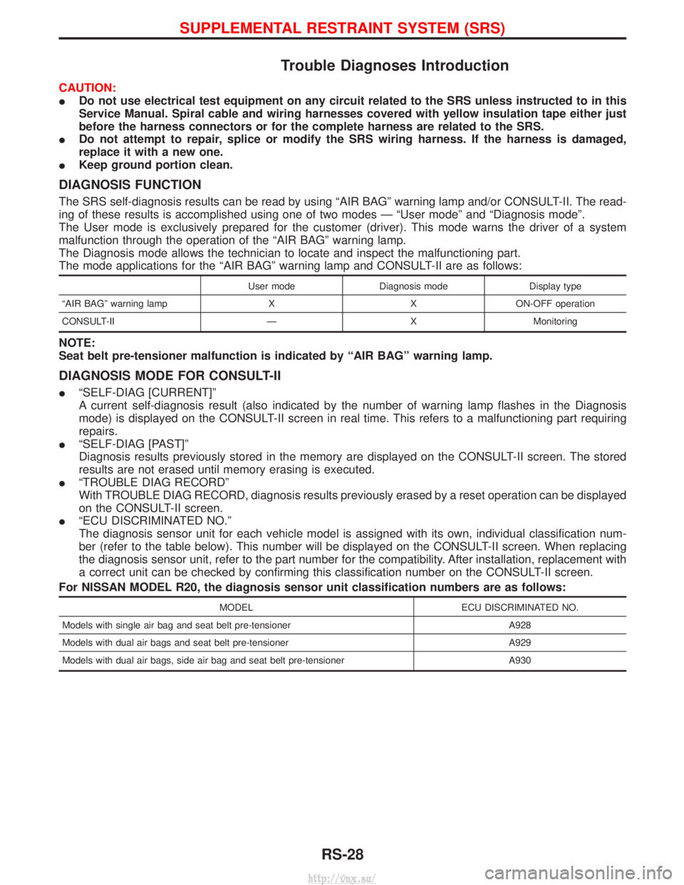
DIAGNOSIS FUNCTION
The SRS self-diagnosis results can be read by using ªAIR BAGº warning lamp and/or CONSULT-II. The read-
ing of these results is accomplished using one of two modes Ð ªUser modeº and ªDiagnosis modeº.
The User mode is exclusively prepared for the customer (driver). This mode warns the driver of a system
malfunction through the operation of the ªAIR BAGº warning lamp.
The Diagnosis mode allows the technician to locate and inspect the malfunctioning part.
The mode applications for the ªAIR BAGº warning lamp and CONSULT-II are as follows:
User mode Diagnosis mode Display type
ªAIR BAGº warning lamp X X ON-OFF operation
CONSULT-II Ð X Monitoring
NOTE:
Seat belt pre-tensioner malfunction is indicated by ªAIR BAGº warning lamp.
DIAGNOSIS MODE FOR CONSULT-II
I ªSELF-DIAG [CURRENT]º
A current self-diagnosis result (also indicated by the number of warning lamp flashes in the Diagnosis
mode) is displayed on the CONSULT-II screen in real time. This refers to a malfunctioning part requiring
repairs.
I ªSELF-DIAG [PAST]º
Diagnosis results previously stored in the memory are displayed on the CONSULT-II screen. The stored
results are not erased until memory erasing is executed.
I ªTROUBLE DIAG RECORDº
With TROUBLE DIAG RECORD, diagnosis results previously erased by a reset operation can be displayed
on the CONSULT-II screen.
I ªECU DISCRIMINATED NO.º
The diagnosis sensor unit for each vehicle model is assigned with its own, individual classification num-
ber (refer to the table below). This number will be displayed on the CONSULT-II screen. When replacing
the diagnosis sensor unit, refer to the part number for the compatibility. After installation, replacement with
a correct unit can be checked by confirming this classification number on the CONSULT-II screen.
For NISSAN MODEL R20, the diagnosis sensor unit classification numbers are as follows:
MODEL ECU DISCRIMINATED NO.
Models with single air bag and seat belt pre-tensioner A928
Models with dual air bags and seat belt pre-tensioner A929
Models with dual air bags, side air bag and seat belt pre-tensioner A930
SUPPLEMENTAL RESTRAINT SYSTEM (SRS)
RS-28
http://vnx.su/
Page 1583 of 1833

Combination Meter Self-Diagnosis
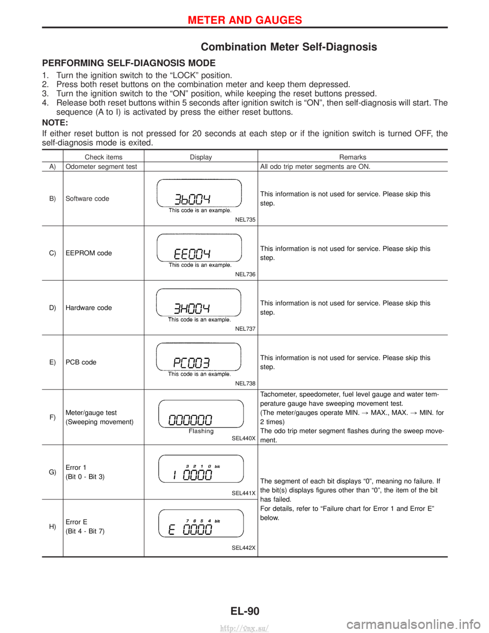
PERFORMING SELF-DIAGNOSIS MODE
1. Turn the ignition switch to the ªLOCKº position.
2. Press both reset buttons on the combination meter and keep them depressed.
3. Turn the ignition switch to the ªONº position, while keeping the reset buttons pressed.
4. Release both reset buttons within 5 seconds after ignition switch is ªONº, then self-diagnosis will start. Thesequence (A to I) is activated by press the either reset buttons.
NOTE:
If either reset button is not pressed for 20 seconds at each step or if the ignition switch is turned OFF, the
self-diagnosis mode is exited.
Check items Display Remarks
A) Odometer segment test All odo trip meter segments are ON.
B) Software code
NEL735
This information is not used for service. Please skip this
step.
C) EEPROM code
NEL736
This information is not used for service. Please skip this
step.
D) Hardware code
NEL737
This information is not used for service. Please skip this
step.
E) PCB code
NEL738
This information is not used for service. Please skip this
step.
F) Meter/gauge test
(Sweeping movement)
SEL440X
Tachometer, speedometer, fuel level gauge and water tem-
perature gauge have sweeping movement test.
(The meter/gauges operate MIN.
,MAX., MAX. ,MIN. for
2 times)
The odo trip meter segment flashes during the sweep move-
ment.
G) Error 1
(Bit 0 - Bit 3)
SEL441X
The segment of each bit displays ª0º, meaning no failure. If
the bit(s) displays figures other than ª0º, the item of the bit
has failed.
For details, refer to ªFailure chart for Error 1 and Error Eº
below.
H) Error E
(Bit 4 - Bit 7)
SEL442X
METER AND GAUGES
EL-90
http://vnx.su/
Page 1627 of 1833

System Description
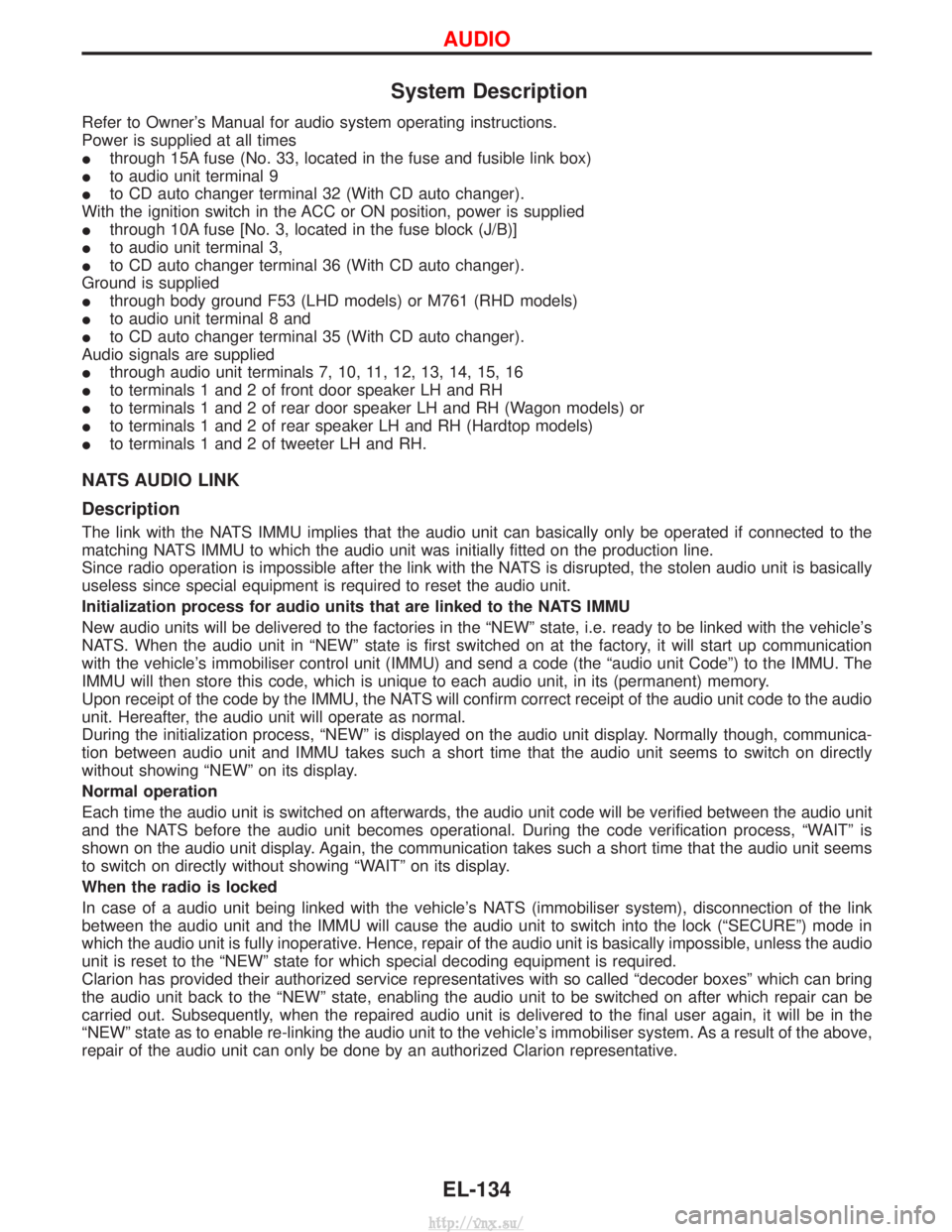
Refer to Owner's Manual for audio system operating instructions.
Power is supplied at all times
Ithrough 15A fuse (No. 33, located in the fuse and fusible link box)
I to audio unit terminal 9
I to CD auto changer terminal 32 (With CD auto changer).
With the ignition switch in the ACC or ON position, power is supplied
I through 10A fuse [No. 3, located in the fuse block (J/B)]
I to audio unit terminal 3,
I to CD auto changer terminal 36 (With CD auto changer).
Ground is supplied
I through body ground F53 (LHD models) or M761 (RHD models)
I to audio unit terminal 8 and
I to CD auto changer terminal 35 (With CD auto changer).
Audio signals are supplied
I through audio unit terminals 7, 10, 11, 12, 13, 14, 15, 16
I to terminals 1 and 2 of front door speaker LH and RH
I to terminals 1 and 2 of rear door speaker LH and RH (Wagon models) or
I to terminals 1 and 2 of rear speaker LH and RH (Hardtop models)
I to terminals 1 and 2 of tweeter LH and RH.
NATS AUDIO LINK
Description
The link with the NATS IMMU implies that the audio unit can basically only be operated if connected to the
matching NATS IMMU to which the audio unit was initially fitted on the production line.
Since radio operation is impossible after the link with the NATS is disrupted, the stolen audio unit is basically
useless since special equipment is required to reset the audio unit.
Initialization process for audio units that are linked to the NATS IMMU
New audio units will be delivered to the factories in the ªNEWº state, i.e. ready to be linked with the vehicle's
NATS. When the audio unit in ªNEWº state is first switched on at the factory, it will start up communication
with the vehicle's immobiliser control unit (IMMU) and send a code (the ªaudio unit Codeº) to the IMMU. The
IMMU will then store this code, which is unique to each audio unit, in its (permanent) memory.
Upon receipt of the code by the IMMU, the NATS will confirm correct receipt of the audio unit code to the audio
unit. Hereafter, the audio unit will operate as normal.
During the initialization process, ªNEWº is displayed on the audio unit display. Normally though, communica-
tion between audio unit and IMMU takes such a short time that the audio unit seems to switch on directly
without showing ªNEWº on its display.
Normal operation
Each time the audio unit is switched on afterwards, the audio unit code will be verified between the audio unit
and the NATS before the audio unit becomes operational. During the code verification process, ªWAITº is
shown on the audio unit display. Again, the communication takes such a short time that the audio unit seems
to switch on directly without showing ªWAITº on its display.
When the radio is locked
In case of a audio unit being linked with the vehicle's NATS (immobiliser system), disconnection of the link
between the audio unit and the IMMU will cause the audio unit to switch into the lock (ªSECUREº) mode in
which the audio unit is fully inoperative. Hence, repair of the audio unit is basically impossible, unless the audio
unit is reset to the ªNEWº state for which special decoding equipment is required.
Clarion has provided their authorized service representatives with so called ªdecoder boxesº which can bring
the audio unit back to the ªNEWº state, enabling the audio unit to be switched on after which repair can be
carried out. Subsequently, when the repaired audio unit is delivered to the final user again, it will be in the
ªNEWº state as to enable re-linking the audio unit to the vehicle's immobiliser system. As a result of the above,
repair of the audio unit can only be done by an authorized Clarion representative.
AUDIO
EL-134
http://vnx.su/
Page 1628 of 1833

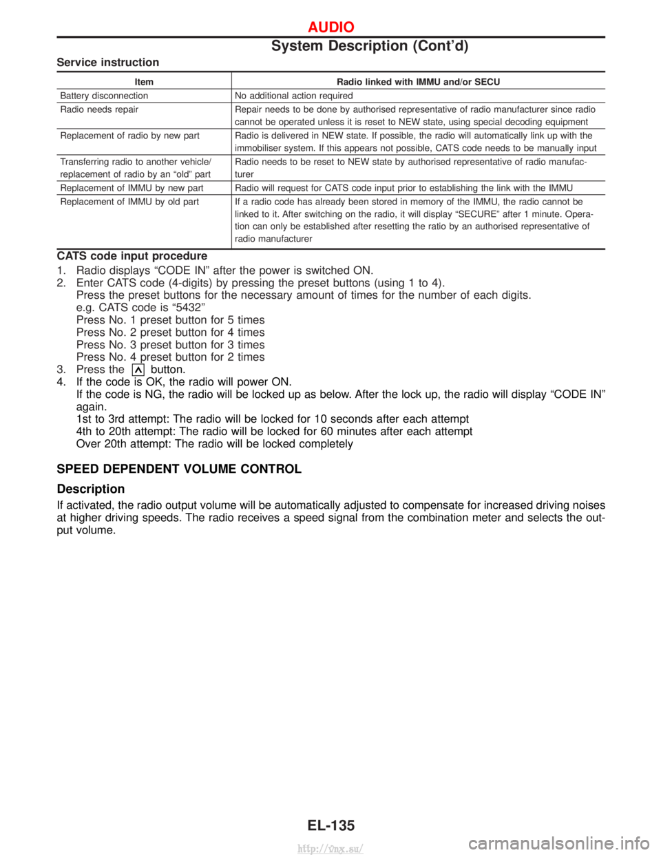
Service instruction
ItemRadio linked with IMMU and/or SECU
Battery disconnection No additional action required
Radio needs repair Repair needs to be done by authorised representative of radio manufacturer since radio cannot be operated unless it is reset to NEW state, using special decoding equipment
Replacement of radio by new part Radio is delivered in NEW state. If possible, the radio will automatically link up with the immobiliser system. If this appears not possible, CATS code needs to be manually input
Transferring radio to another vehicle/
replacement of radio by an ªoldº part Radio needs to be reset to NEW state by authorised representative of radio manufac-
turer
Replacement of IMMU by new part Radio will request for CATS code input prior to establishing the link with the IMMU
Replacement of IMMU by old part If a radio code has already been stored in memory of the IMMU, the radio cannot be linked to it. After switching on the radio, it will display ªSECUREº after 1 minute. Opera-
tion can only be established after resetting the ratio by an authorised representative of
radio manufacturer
CATS code input procedure
1. Radio displays ªCODE INº after the power is switched ON.
2. Enter CATS code (4-digits) by pressing the preset buttons (using 1 to 4).Press the preset buttons for the necessary amount of times for the number of each digits.
e.g. CATS code is ª5432º
Press No. 1 preset button for 5 times
Press No. 2 preset button for 4 times
Press No. 3 preset button for 3 times
Press No. 4 preset button for 2 times
3. Press the
button.
4. If the code is OK, the radio will power ON. If the code is NG, the radio will be locked up as below. After the lock up, the radio will display ªCODE INº
again.
1st to 3rd attempt: The radio will be locked for 10 seconds after each attempt
4th to 20th attempt: The radio will be locked for 60 minutes after each attempt
Over 20th attempt: The radio will be locked completely
SPEED DEPENDENT VOLUME CONTROL
Description
If activated, the radio output volume will be automatically adjusted to compensate for increased driving noises
at higher driving speeds. The radio receives a speed signal from the combination meter and selects the out-
put volume.
AUDIO
System Description (Cont'd)
EL-135
http://vnx.su/