Door unlock NISSAN TERRANO 2004 Service Repair Manual
[x] Cancel search | Manufacturer: NISSAN, Model Year: 2004, Model line: TERRANO, Model: NISSAN TERRANO 2004Pages: 1833, PDF Size: 53.42 MB
Page 1553 of 1833

or M33, M754 (RHD models).
Ground is supplied to terminal 4 of each rear combination lamp through body grounds B10 and B18.
With power and ground supplied, the time control unit controls the flashing of the hazard warning lamps, and
time control unit supplies power to combination meter terminals 7 or 33, to flash hazard warning indicator.
HAZARD REMINDER OPERATION FOR MULTI-REMOTE CONTROL SYSTEM
When the doors are locked or unlocked by multi-remote controller, time control unit controls turn lamps haz-
ard reminder flashes as follows.
ILocked operation: Flash once
I Unlock operation: Flash twice
EXTERIOR LAMP
System Description (Cont'd)
EL-60
http://vnx.su/
Page 1565 of 1833
![NISSAN TERRANO 2004 Service Repair Manual System Description
POWER SUPPLY AND GROUND
Power is supplied at all times:
Ithrough 15A fuse [No. 5, located in the fuse block (J/B)]
I to time control unit terminal U09,
I through 10A fuse [No. 16, l NISSAN TERRANO 2004 Service Repair Manual System Description
POWER SUPPLY AND GROUND
Power is supplied at all times:
Ithrough 15A fuse [No. 5, located in the fuse block (J/B)]
I to time control unit terminal U09,
I through 10A fuse [No. 16, l](/img/5/57394/w960_57394-1564.png)
System Description
POWER SUPPLY AND GROUND
Power is supplied at all times:
Ithrough 15A fuse [No. 5, located in the fuse block (J/B)]
I to time control unit terminal U09,
I through 10A fuse [No. 16, located in the fuse block (J/B)]
I to front interior lamp terminal 1,
I to rear interior lamp terminal 1 (Wagon models)
I to rear room lamp terminal 2 (Hardtop models)
I to sunroof switch and map lamps terminal 3 (with sunroof),
I to map lamp terminal 2 (without sunroof).
Ground is supplied:
I through body grounds terminals F36, F47 (LHD models) or M33, M754 (RHD models).
I through fuse block terminal MM2
I to time control unit terminal U16
When the driver side door is opened, ground is supplied:
I through driver side door switch case ground and terminal 1, and
I through fuse block terminal B07
I to time control unit terminal U06
When any door is opened, ground is supplied:
I through case ground and terminal 1 of each door switch,
I through fuse block terminal B01
I to time control unit terminal U07.
When the driver side door is unlocked by the door lock/unlock switch, the time control unit receives a ground
signal:
I through body grounds B10 and B18
I to power window main switch terminal 3
I from power window main switch terminal 7
I to time control unit terminal U37.
When a signal, or combination of signals is received by the time control unit, ground is supplied:
I through time control unit terminal U12 and fuse block terminal R01
I to front interior room lamp terminal 2.
I to rear interior lamp terminal 2 (Wagon models).
I to rear interior room lamp terminal 1 (Hardtop models).
With power and ground supplied, the interior room lamps illuminate when the lamp switch is in ªDOORº posi-
tion.
SWITCH OPERATION
When interior room lamp switch is in ªONº position, ground is supplied:
I through front interior lamp case ground.
I through rear interior lamp case ground (Wagon models).
When sunroof switch and map lamps (with sunroof) is ON, ground is supplied:
I through body grounds F36, F47 (LHD models) or M33, M754 (RHD models)
I through fuse block terminal MM2 and R03
I to sunroof switch map lamps terminal 2.
When map lamp (without sunroof) is ON, ground is supplied:
I through body grounds F36, F47 (LHD models) or M33, M754 (RHD models)
I through fuse block terminal MM2 and R03
I to map lamp terminal 1.
With power and ground supplied, the interior room lamps, map lamps illuminate.
INTERIOR ROOM LAMP TIMER OPERATION
When interior room lamp switch is in the ªDOORº position, the time control unit keeps the interior room lamp
illuminated for about 30 seconds when:
I unlock signal is supplied from door lock/unlock switch while all doors are closed
I unlock signal is supplied from remote controller or door key cylinder while all doors are closed
I driver's door is opened and then closed
The timer is canceled when:
I driver's door is locked,
INTERIOR LAMP
EL-72
http://vnx.su/
Page 1571 of 1833
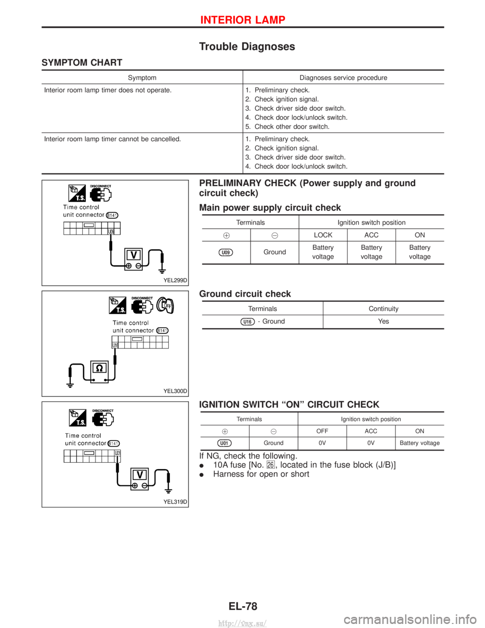
Trouble Diagnoses
SYMPTOM CHART
SymptomDiagnoses service procedure
Interior room lamp timer does not operate. 1. Preliminary check.
2. Check ignition signal.
3. Check driver side door switch.
4. Check door lock/unlock switch.
5. Check other door switch.
Interior room lamp timer cannot be cancelled. 1. Preliminary check.
2. Check ignition signal.
3. Check driver side door switch.
4. Check door lock/unlock switch.
PRELIMINARY CHECK (Power supply and ground
circuit check)
Main power supply circuit check
Terminals Ignition switch position
!@ LOCK ACC ON
U09GroundBattery
voltage Battery
voltage Battery
voltage
Ground circuit check
Terminals Continuity
U16- GroundYes
IGNITION SWITCH ªONº CIRCUIT CHECK
TerminalsIgnition switch position
!@ OFFACC ON
U01Ground 0V0V Battery voltage
If NG, check the following.
I10A fuse [No.
26, located in the fuse block (J/B)]
IHarness for open or short
YEL299D
YEL300D
YEL319D
INTERIOR LAMP
EL-78
http://vnx.su/
Page 1573 of 1833
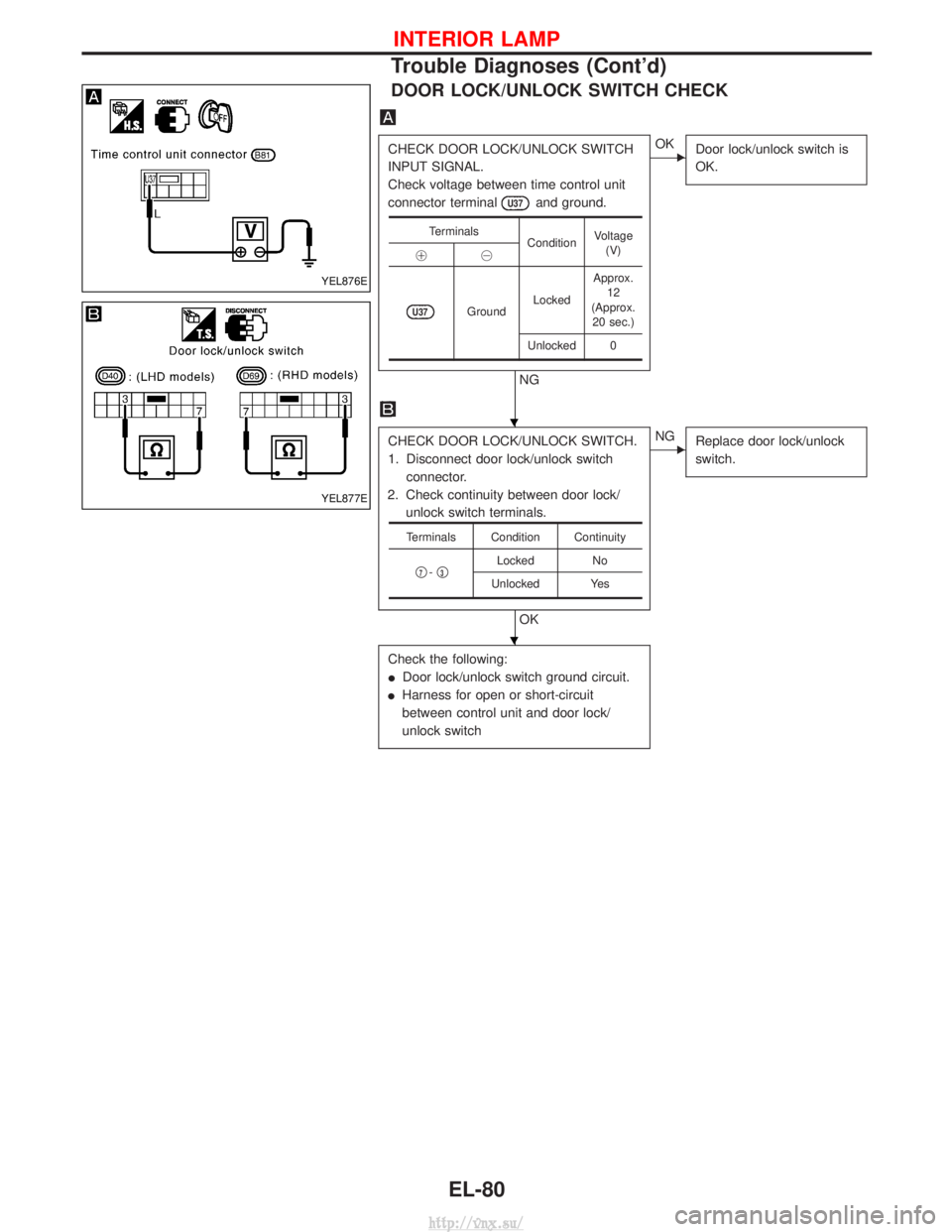
DOOR LOCK/UNLOCK SWITCH CHECK
CHECK DOOR LOCK/UNLOCK SWITCH
INPUT SIGNAL.
Check voltage between time control unit
connector terminal
U37and ground.
NG
EOKDoor lock/unlock switch is
OK.
CHECK DOOR LOCK/UNLOCK SWITCH.
1. Disconnect door lock/unlock switch
connector.
2. Check continuity between door lock/ unlock switch terminals.
OK
ENG Replace door lock/unlock
switch.
Check the following:
IDoor lock/unlock switch ground circuit.
I Harness for open or short-circuit
between control unit and door lock/
unlock switch
Terminals
ConditionVoltage
(V)
!@
U37Ground LockedApprox.
12
(Approx. 20 sec.)
Unlocked 0
Terminals Condition Continuity
q
7-q3Locked
No
Unlocked Yes
YEL876E
YEL877E
H
H
INTERIOR LAMP
Trouble Diagnoses (Cont'd)
EL-80
http://vnx.su/
Page 1656 of 1833
System Description
OPERATION
Power door lock/unlock operation by door key cylinder
IWith the key inserted into front door key cylinder, turning it to LOCK will lock all doors.
I With the key inserted into front door key cylinder, turning it to UNLOCK will unlock all doors.
Power door lock/unlock operation by multi-remote controller
I Pressing multi-remote controller LOCK button will lock all doors.
I Pressing multi-remote controller UNLOCK button once will unlock driver door. Then, if an unlock signal is
sent from the remote controller again within 5 seconds, all other doors will be unlocked.
Power door lock/unlock operation by lock/unlock switch
I With lock/unlock switch on driver door trim setting to LOCK will lock all doors.
I With lock/unlock switch on driver door trim setting to UNLOCK will unlock all doors.
Key reminder system
I If the ignition key is in the ignition key cylinder and driver door is open, setting lock/unlock switch, lock
knob, key or multi-remote controller to ªLOCKº locks the door once but then immediately unlocks all doors.
(signal from door unlock sensor driver side)
POWER DOOR LOCK
EL-163
http://vnx.su/
Page 1664 of 1833
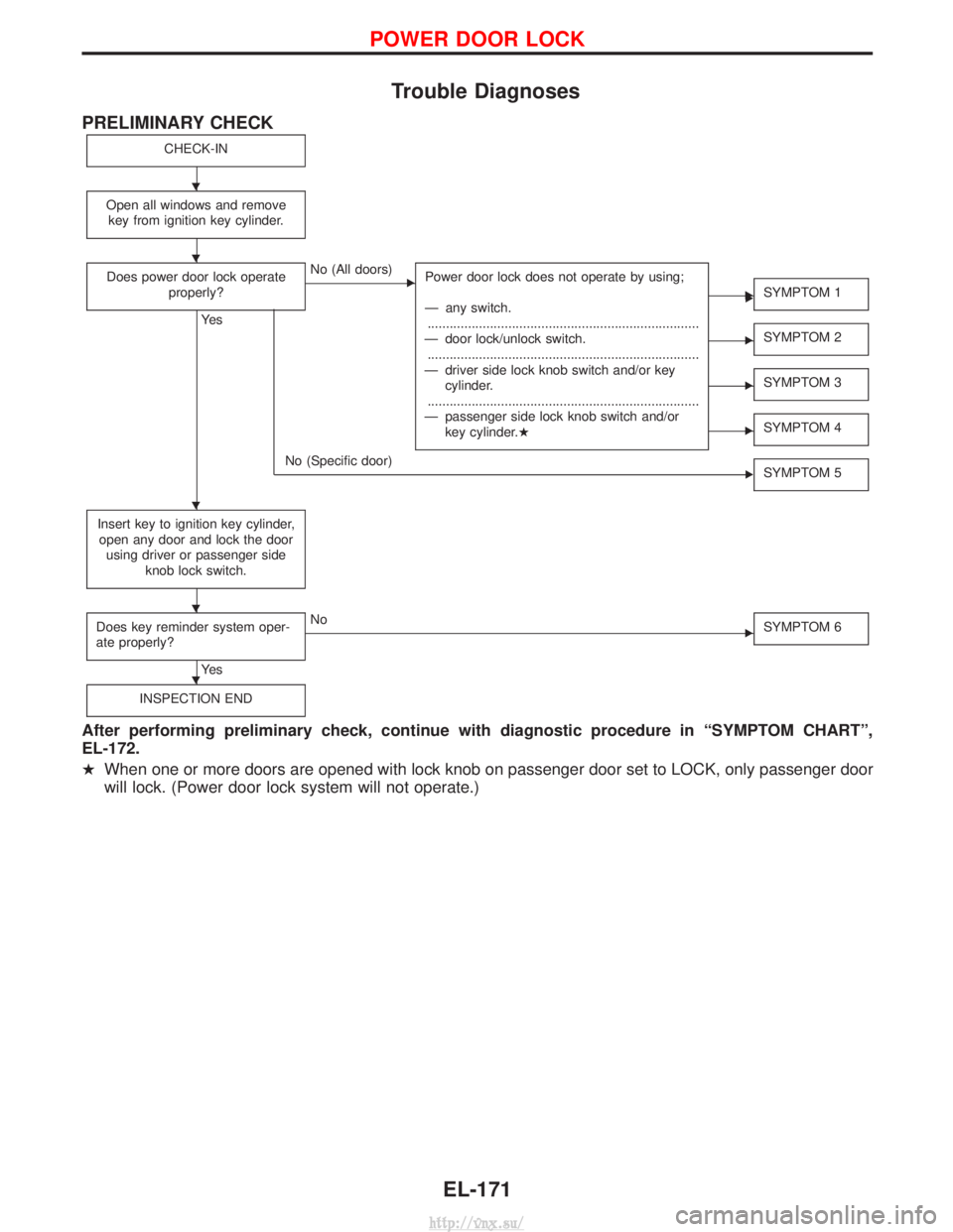
Trouble Diagnoses
PRELIMINARY CHECK
CHECK-IN
Open all windows and removekey from ignition key cylinder.
Does power door lock operate properly?
Ye s
ENo (All doors) Power door lock does not operate by using;
Ð any switch.
........................................................................\
..
Ð door lock/unlock switch. ........................................................................\
..
Ð driver side lock knob switch and/or key cylinder.
........................................................................\
..
Ð passenger side lock knob switch and/or key cylinder.H
ESYMPTOM 1
ESYMPTOM 2
ESYMPTOM 3
ESYMPTOM 4
No (Specific door) SYMPTOM 5
Insert key to ignition key cylinder,
open any door and lock the door using driver or passenger side knob lock switch.
Does key reminder system oper-
ate properly?
Ye s
ENo SYMPTOM 6
INSPECTION END
After performing preliminary check, continue with diagnostic procedure in ªSYMPTOM CHARTº,
EL-172.
HWhen one or more doors are opened with lock knob on passenger door set to LOCK, only passenger door
will lock. (Power door lock system will not operate.)
E E
H
H
H
H
H
POWER DOOR LOCK
EL-171
http://vnx.su/
Page 1665 of 1833
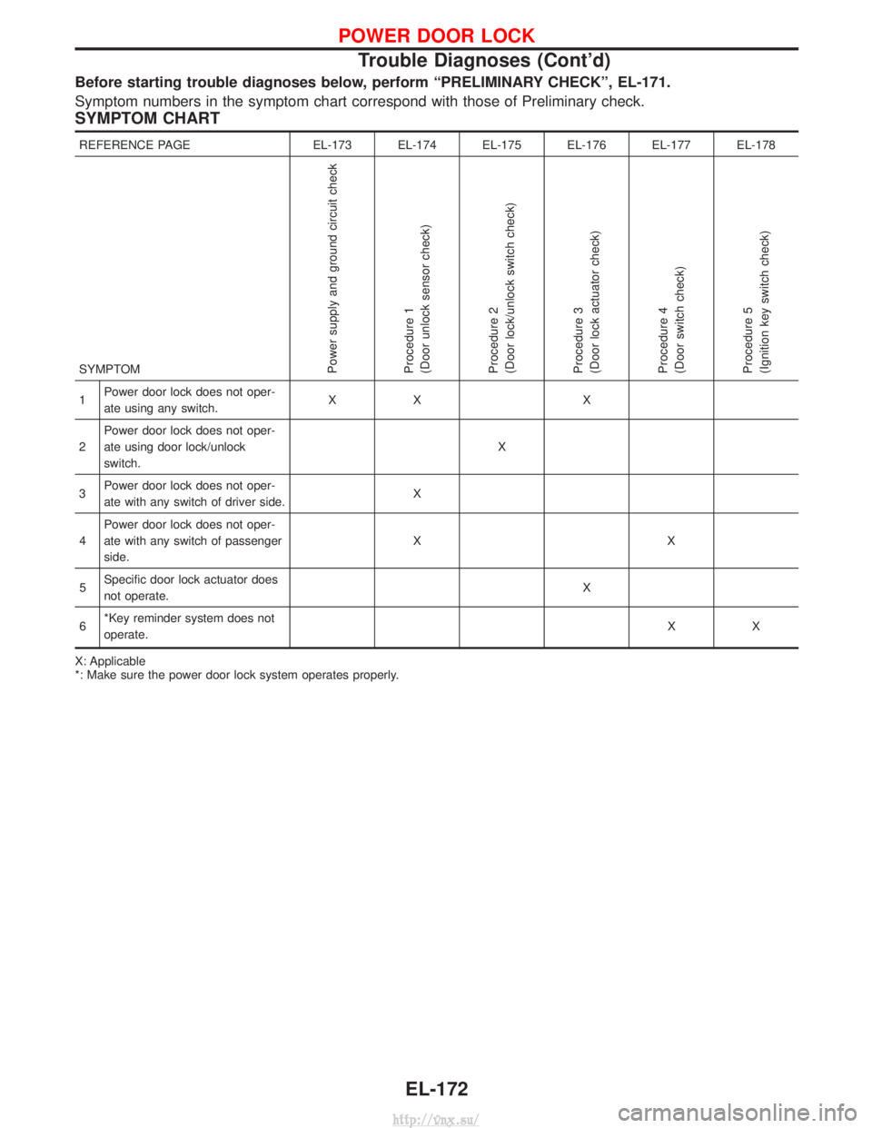
Before starting trouble diagnoses below, perform ªPRELIMINARY CHECKº, EL-171.
Symptom numbers in the symptom chart correspond with those of Preliminary check.
SYMPTOM CHART
REFERENCE PAGEEL-173 EL-174 EL-175 EL-176 EL-177 EL-178
SYMPTOM
Power supply and ground circuit check
Procedure 1
(Door unlock sensor check)
Procedure 2
(Door lock/unlock switch check)
Procedure 3
(Door lock actuator check)
Procedure 4
(Door switch check)
Procedure 5
(Ignition key switch check)
1 Power door lock does not oper-
ate using any switch. XX X
2 Power door lock does not oper-
ate using door lock/unlock
switch. X
3 Power door lock does not oper-
ate with any switch of driver side. X
4 Power door lock does not oper-
ate with any switch of passenger
side. XX
5 Specific door lock actuator does
not operate. X
6 *Key reminder system does not
operate. XX
X: Applicable
*: Make sure the power door lock system operates properly.
POWER DOOR LOCK
Trouble Diagnoses (Cont'd)
EL-172
http://vnx.su/
Page 1667 of 1833
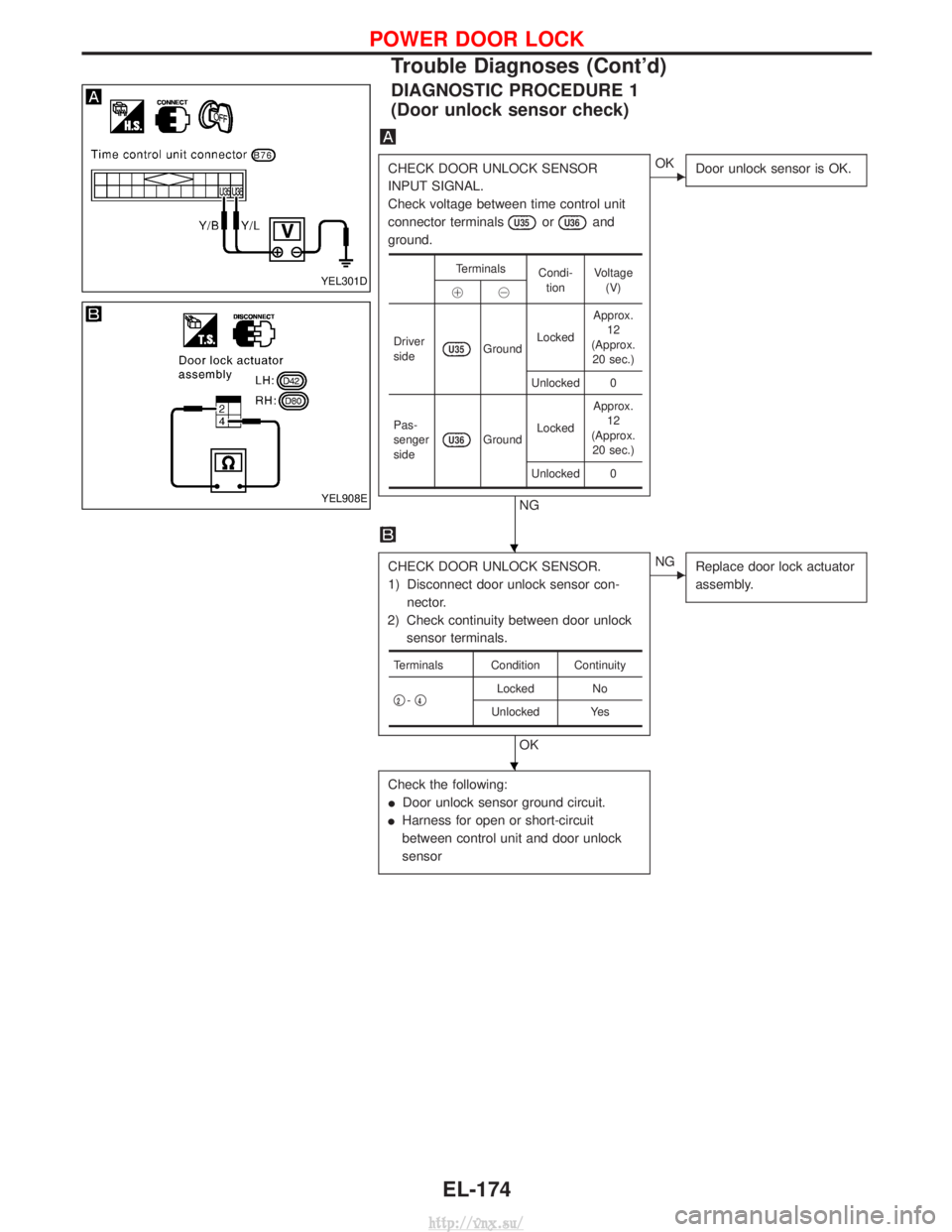
DIAGNOSTIC PROCEDURE 1
(Door unlock sensor check)
CHECK DOOR UNLOCK SENSOR
INPUT SIGNAL.
Check voltage between time control unit
connector terminals
U35orU36and
ground.
NG
EOK Door unlock sensor is OK.
CHECK DOOR UNLOCK SENSOR.
1) Disconnect door unlock sensor con-
nector.
2) Check continuity between door unlock sensor terminals.
OK
ENG Replace door lock actuator
assembly.
Check the following:
IDoor unlock sensor ground circuit.
I Harness for open or short-circuit
between control unit and door unlock
sensor
Terminals
Condi-
tion Voltage
(V)
!@
Driver
side
U35Ground Locked Approx.
12
(Approx. 20 sec.)
Unlocked 0
Pas-
senger
side
U36Ground Locked Approx.
12
(Approx. 20 sec.)
Unlocked 0
Terminals Condition Continuity
q
2- q4Locked
No
Unlocked Yes
YEL301D
YEL908E
H
H
POWER DOOR LOCK
Trouble Diagnoses (Cont'd)
EL-174
http://vnx.su/
Page 1668 of 1833
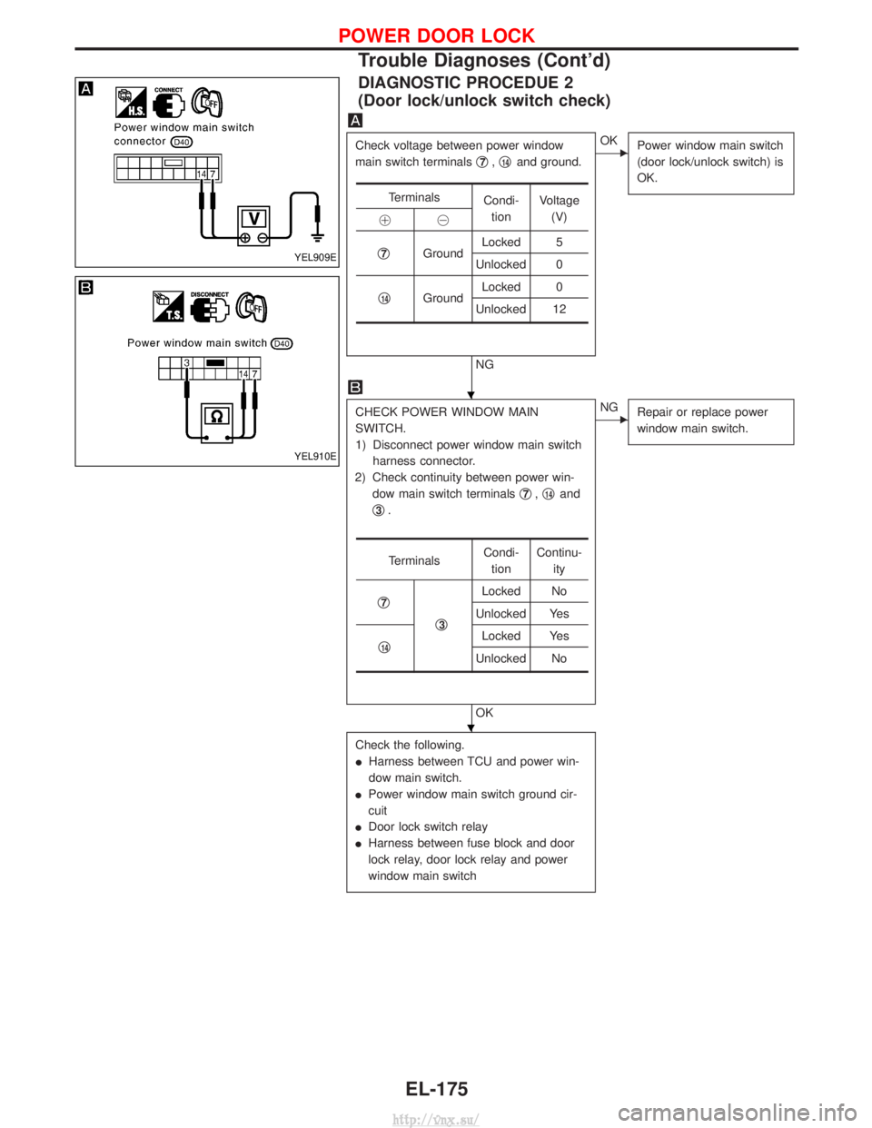
DIAGNOSTIC PROCEDUE 2
(Door lock/unlock switch check)
Check voltage between power window
main switch terminalsq
7,q14and ground.
NG
EOK
Power window main switch
(door lock/unlock switch) is
OK.
CHECK POWER WINDOW MAIN
SWITCH.
1) Disconnect power window main switch
harness connector.
2) Check continuity between power win- dow main switch terminals q
7,q14and
q
3.
OK
ENG Repair or replace power
window main switch.
Check the following.
IHarness between TCU and power win-
dow main switch.
I Power window main switch ground cir-
cuit
I Door lock switch relay
I Harness between fuse block and door
lock relay, door lock relay and power
window main switch
Terminals
Condi-
tion Voltage
(V)
!@
q
7Ground Locked 5
Unlocked 0
q
14Ground Locked 0
Unlocked 12
Terminals Condi-
tion Continu-
ity
q
7
q3
Locked No
Unlocked Yes
q
14Locked Yes
Unlocked No
YEL909E
YEL910E
H
H
POWER DOOR LOCK
Trouble Diagnoses (Cont'd)
EL-175
http://vnx.su/
Page 1669 of 1833
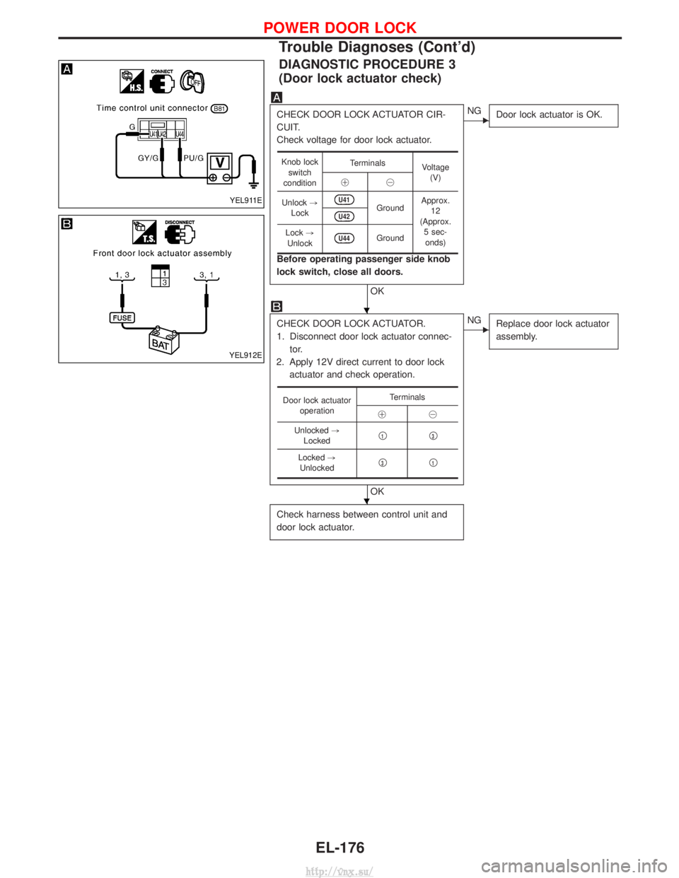
DIAGNOSTIC PROCEDURE 3
(Door lock actuator check)
CHECK DOOR LOCK ACTUATOR CIR-
CUIT.
Check voltage for door lock actuator.
Before operating passenger side knob
lock switch, close all doors.
OK
ENGDoor lock actuator is OK.
CHECK DOOR LOCK ACTUATOR.
1. Disconnect door lock actuator connec-
tor.
2. Apply 12V direct current to door lock actuator and check operation.
OK
ENG Replace door lock actuator
assembly.
Check harness between control unit and
door lock actuator.
Knob lock
switch
condition Terminals
Voltage
(V)
!@
Unlock ,
Lock
U41Ground Approx.
12
(Approx. 5 sec-onds)U42
Lock ,
UnlockU44Ground
Door lock actuator operation Terminals
!@
Unlocked ,
Locked q
1q3
Locked
,
Unlocked q3q1
YEL911E
YEL912E
H
H
POWER DOOR LOCK
Trouble Diagnoses (Cont'd)
EL-176
http://vnx.su/