fuse box diagram NISSAN TERRANO 2004 Service Repair Manual
[x] Cancel search | Manufacturer: NISSAN, Model Year: 2004, Model line: TERRANO, Model: NISSAN TERRANO 2004Pages: 1833, PDF Size: 53.42 MB
Page 15 of 1833
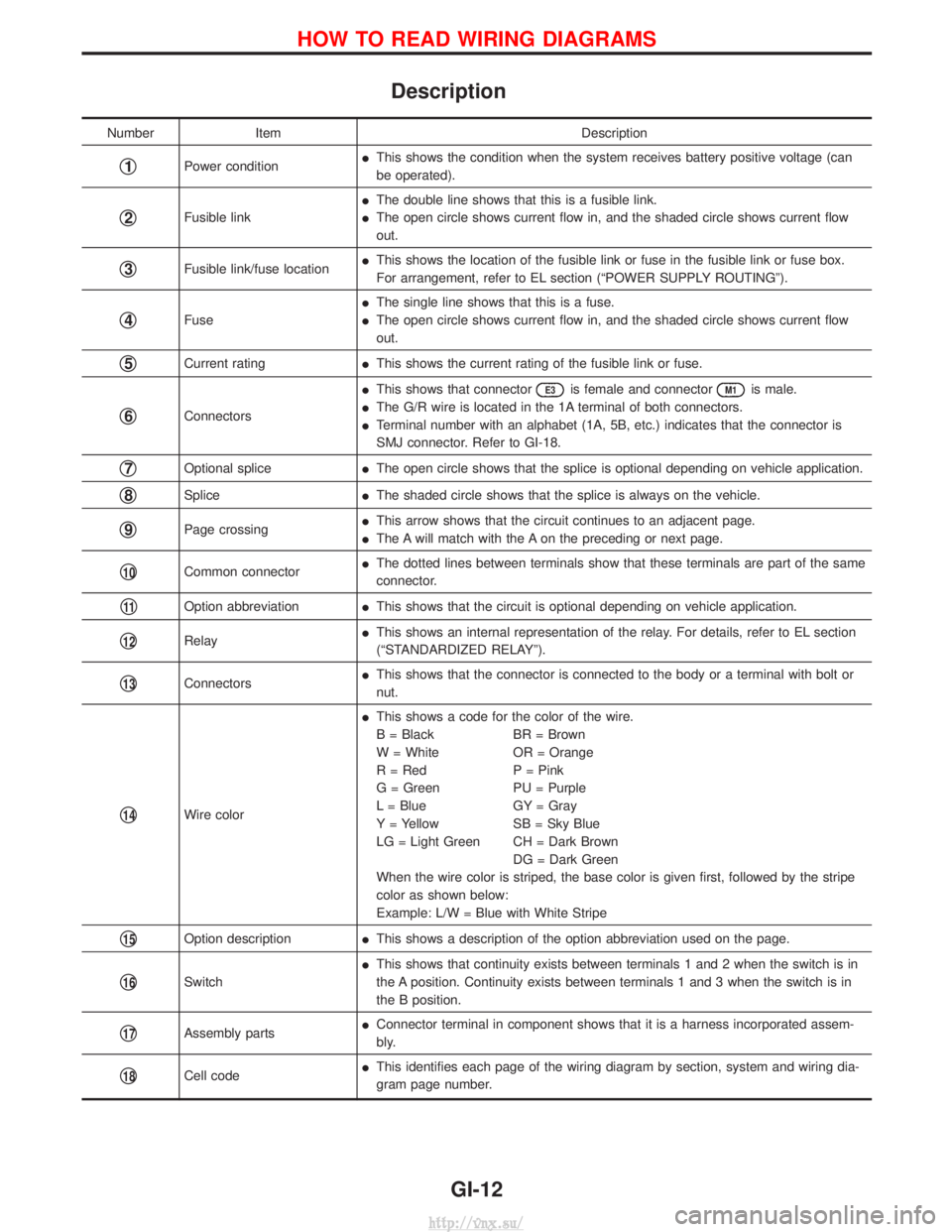
Description
NumberItem Description
q1Power conditionI
This shows the condition when the system receives battery positive voltage (can
be operated).
q2Fusible link I
The double line shows that this is a fusible link.
I The open circle shows current flow in, and the shaded circle shows current flow
out.
q3Fusible link/fuse location I
This shows the location of the fusible link or fuse in the fusible link or fuse box.
For arrangement, refer to EL section (ªPOWER SUPPLY ROUTINGº).
q4Fuse I
The single line shows that this is a fuse.
I The open circle shows current flow in, and the shaded circle shows current flow
out.
q5Current rating IThis shows the current rating of the fusible link or fuse.
q6Connectors I
This shows that connector
E3is female and connectorM1is male.
I The G/R wire is located in the 1A terminal of both connectors.
I Terminal number with an alphabet (1A, 5B, etc.) indicates that the connector is
SMJ connector. Refer to GI-18.
q7Optional splice IThe open circle shows that the splice is optional depending on vehicle application.
q8Splice IThe shaded circle shows that the splice is always on the vehicle.
q9Page crossing I
This arrow shows that the circuit continues to an adjacent page.
I The A will match with the A on the preceding or next page.
q10Common connector I
The dotted lines between terminals show that these terminals are part of the same
connector.
q11Option abbreviation IThis shows that the circuit is optional depending on vehicle application.
q12Relay I
This shows an internal representation of the relay. For details, refer to EL section
(ªSTANDARDIZED RELAYº).
q13Connectors I
This shows that the connector is connected to the body or a terminal with bolt or
nut.
q14Wire color I
This shows a code for the color of the wire.
B = Black BR = Brown
W = White OR = Orange
R = Red P = Pink
G = Green PU = Purple
L = Blue GY = Gray
Y = Yellow SB = Sky Blue
LG = Light Green CH = Dark Brown
DG = Dark Green
When the wire color is striped, the base color is given first, followed by the stripe
color as shown below:
Example: L/W = Blue with White Stripe
q15Option description IThis shows a description of the option abbreviation used on the page.
q16Switch I
This shows that continuity exists between terminals 1 and 2 when the switch is in
the A position. Continuity exists between terminals 1 and 3 when the switch is in
the B position.
q17Assembly parts I
Connector terminal in component shows that it is a harness incorporated assem-
bly.
q18Cell code I
This identifies each page of the wiring diagram by section, system and wiring dia-
gram page number.
HOW TO READ WIRING DIAGRAMS
GI-12
http://vnx.su/
Page 16 of 1833
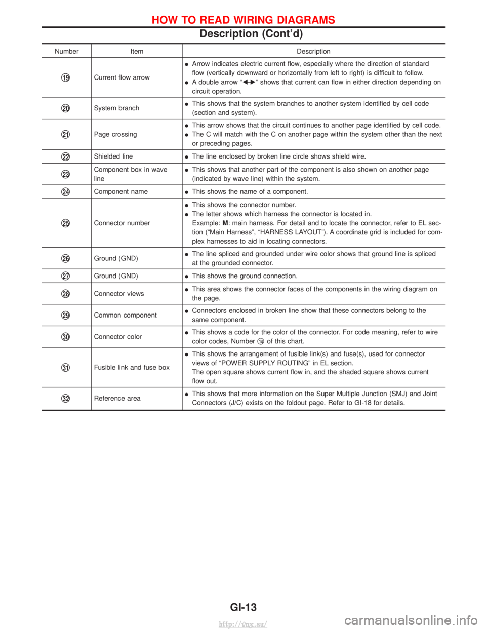
NumberItem Description
q19Current flow arrowI
Arrow indicates electric current flow, especially where the direction of standard
flow (vertically downward or horizontally from left to right) is difficult to follow.
I A double arrow ªF Ð
Eº shows that current can flow in either direction depending on
circuit operation.
q20System branch I
This shows that the system branches to another system identified by cell code
(section and system).
q21Page crossing I
This arrow shows that the circuit continues to another page identified by cell code.
I The C will match with the C on another page within the system other than the next
or preceding pages.
q22Shielded line IThe line enclosed by broken line circle shows shield wire.
q23Component box in wave
line I
This shows that another part of the component is also shown on another page
(indicated by wave line) within the system.
q24Component name IThis shows the name of a component.
q25Connector number I
This shows the connector number.
I The letter shows which harness the connector is located in.
Example: M: main harness. For detail and to locate the connector, refer to EL sec-
tion (ªMain Harnessº, ªHARNESS LAYOUTº). A coordinate grid is included for com-
plex harnesses to aid in locating connectors.
q26Ground (GND) I
The line spliced and grounded under wire color shows that ground line is spliced
at the grounded connector.
q27Ground (GND) IThis shows the ground connection.
q28Connector views I
This area shows the connector faces of the components in the wiring diagram on
the page.
q29Common component I
Connectors enclosed in broken line show that these connectors belong to the
same component.
q30Connector color I
This shows a code for the color of the connector. For code meaning, refer to wire
color codes, Number q14of this chart.
q31Fusible link and fuse box I
This shows the arrangement of fusible link(s) and fuse(s), used for connector
views of ªPOWER SUPPLY ROUTINGº in EL section.
The open square shows current flow in, and the shaded square shows current
flow out.
q32Reference area I
This shows that more information on the Super Multiple Junction (SMJ) and Joint
Connectors (J/C) exists on the foldout page. Refer to GI-18 for details.
HOW TO READ WIRING DIAGRAMS
Description (Cont'd)
GI-13
http://vnx.su/
Page 652 of 1833
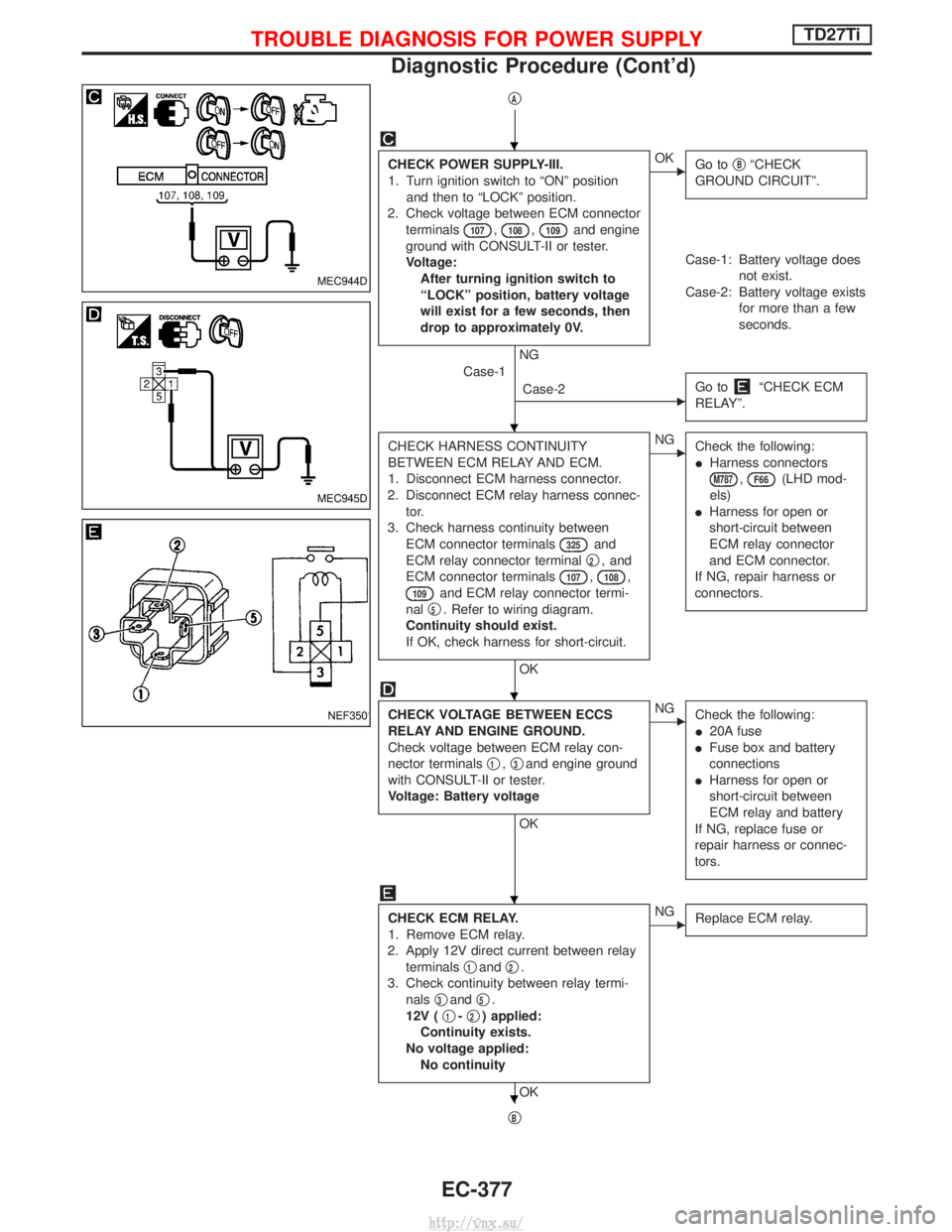
qA
CHECK POWER SUPPLY-III.
1. Turn ignition switch to ªONº positionand then to ªLOCKº position.
2. Check voltage between ECM connector terminals
107,108,109and engine
ground with CONSULT-II or tester.
Voltage: After turning ignition switch to
ªLOCKº position, battery voltage
will exist for a few seconds, then
drop to approximately 0V.
NG
EOK Go toqBªCHECK
GROUND CIRCUITº.
Case-1: Battery voltage does not exist.
Case-2: Battery voltage exists for more than a few
seconds.
Case-1 Case-2
EGo toªCHECK ECM
RELAYº.
CHECK HARNESS CONTINUITY
BETWEEN ECM RELAY AND ECM.
1. Disconnect ECM harness connector.
2. Disconnect ECM relay harness connec- tor.
3. Check harness continuity between ECM connector terminals
325and
ECM relay connector terminal q
2, and
ECM connector terminals
107,108,
109and ECM relay connector termi-
nal q
5. Refer to wiring diagram.
Continuity should exist.
If OK, check harness for short-circuit.
OK
ENG Check the following:
IHarness connectors
M787,F66(LHD mod-
els)
I Harness for open or
short-circuit between
ECM relay connector
and ECM connector.
If NG, repair harness or
connectors.
CHECK VOLTAGE BETWEEN ECCS
RELAY AND ENGINE GROUND.
Check voltage between ECM relay con-
nector terminals q
1,q3and engine ground
with CONSULT-II or tester.
Voltage: Battery voltage
OK
ENG Check the following:
I20A fuse
I Fuse box and battery
connections
I Harness for open or
short-circuit between
ECM relay and battery
If NG, replace fuse or
repair harness or connec-
tors.
CHECK ECM RELAY.
1. Remove ECM relay.
2. Apply 12V direct current between relay terminals q
1andq2.
3. Check continuity between relay termi- nals q
3andq5.
12V ( q
1-q2) applied:
Continuity exists.
No voltage applied: No continuity
OK
ENG Replace ECM relay.
qB
MEC944D
MEC945D
NEF350
H
H
H
H
H
TROUBLE DIAGNOSIS FOR POWER SUPPLYTD27Ti
Diagnostic Procedure (Cont'd)
EC-377
http://vnx.su/
Page 668 of 1833
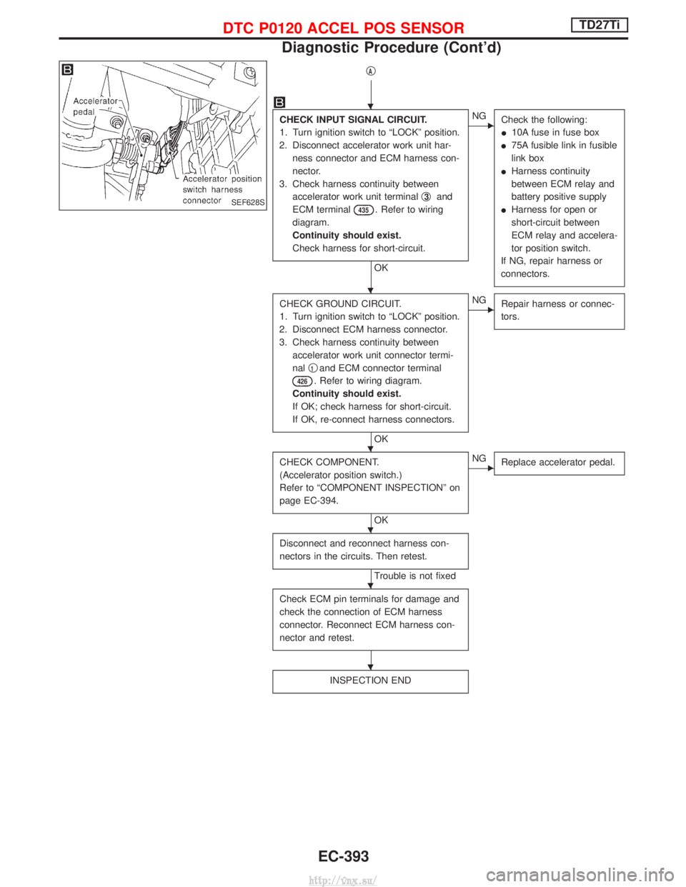
qA
CHECK INPUT SIGNAL CIRCUIT.
1. Turn ignition switch to ªLOCKº position.
2. Disconnect accelerator work unit har- ness connector and ECM harness con-
nector.
3. Check harness continuity between accelerator work unit terminal q
3and
ECM terminal
435. Refer to wiring
diagram.
Continuity should exist.
Check harness for short-circuit.
OK
ENG Check the following:
I10A fuse in fuse box
I 75A fusible link in fusible
link box
I Harness continuity
between ECM relay and
battery positive supply
I Harness for open or
short-circuit between
ECM relay and accelera-
tor position switch.
If NG, repair harness or
connectors.
CHECK GROUND CIRCUIT.
1. Turn ignition switch to ªLOCKº position.
2. Disconnect ECM harness connector.
3. Check harness continuity between accelerator work unit connector termi-
nal q
1and ECM connector terminal
426. Refer to wiring diagram.
Continuity should exist.
If OK; check harness for short-circuit.
If OK, re-connect harness connectors.
OK
ENG Repair harness or connec-
tors.
CHECK COMPONENT.
(Accelerator position switch.)
Refer to ªCOMPONENT INSPECTIONº on
page EC-394.
OK
ENGReplace accelerator pedal.
Disconnect and reconnect harness con-
nectors in the circuits. Then retest.
Trouble is not fixed
Check ECM pin terminals for damage and
check the connection of ECM harness
connector. Reconnect ECM harness con-
nector and retest.
INSPECTION END
SEF628S
H
H
H
H
H
H
DTC P0120 ACCEL POS SENSORTD27Ti
Diagnostic Procedure (Cont'd)
EC-393
http://vnx.su/
Page 681 of 1833
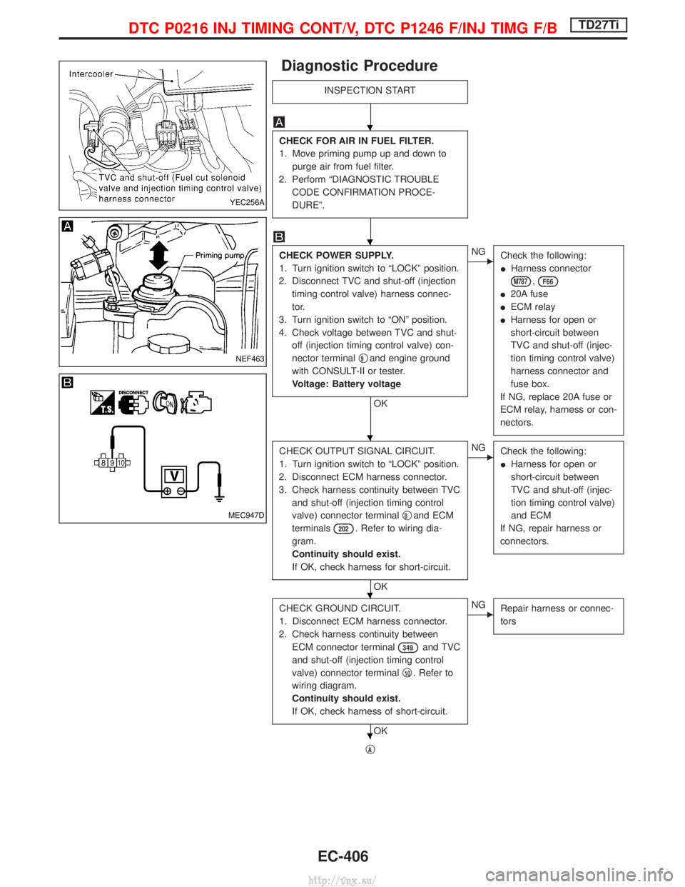
Diagnostic Procedure
INSPECTION START
CHECK FOR AIR IN FUEL FILTER.
1. Move priming pump up and down topurge air from fuel filter.
2. Perform ªDIAGNOSTIC TROUBLE CODE CONFIRMATION PROCE-
DUREº.
CHECK POWER SUPPLY.
1. Turn ignition switch to ªLOCKº position.
2. Disconnect TVC and shut-off (injection timing control valve) harness connec-
tor.
3. Turn ignition switch to ªONº position.
4. Check voltage between TVC and shut- off (injection timing control valve) con-
nector terminal q
9and engine ground
with CONSULT-II or tester.
Voltage: Battery voltage
OK
ENG Check the following:
IHarness connector
M787,F66
I20A fuse
I ECM relay
I Harness for open or
short-circuit between
TVC and shut-off (injec-
tion timing control valve)
harness connector and
fuse box.
If NG, replace 20A fuse or
ECM relay, harness or con-
nectors.
CHECK OUTPUT SIGNAL CIRCUIT.
1. Turn ignition switch to ªLOCKº position.
2. Disconnect ECM harness connector.
3. Check harness continuity between TVC and shut-off (injection timing control
valve) connector terminal q
8and ECM
terminals
202. Refer to wiring dia-
gram.
Continuity should exist.
If OK, check harness for short-circuit.
OK
ENG Check the following:
IHarness for open or
short-circuit between
TVC and shut-off (injec-
tion timing control valve)
and ECM
If NG, repair harness or
connectors.
CHECK GROUND CIRCUIT.
1. Disconnect ECM harness connector.
2. Check harness continuity between ECM connector terminal
349and TVC
and shut-off (injection timing control
valve) connector terminal q
10. Refer to
wiring diagram.
Continuity should exist.
If OK, check harness of short-circuit.
OK
ENG Repair harness or connec-
tors
qA
YEC256A
NEF463
MEC947D
H
H
H
H
H
DTC P0216 INJ TIMING CONT/V, DTC P1246 F/INJ TIMG F/BTD27Ti
EC-406
http://vnx.su/
Page 691 of 1833
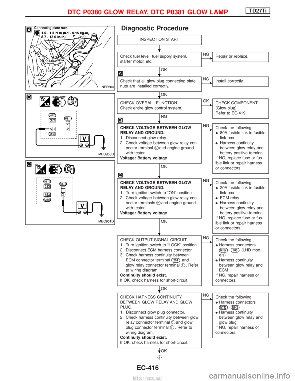
Diagnostic Procedure
INSPECTION START
Check fuel level, fuel supply system,
starter motor, etc.
OK
ENGRepair or replace.
Check that all glow plug connecting plate
nuts are installed correctly.
OK
ENGInstall correctly.
CHECK OVERALL FUNCTION.
Check entire glow control system.
NG
EOKCHECK COMPONENT
(Glow plug).
Refer to EC-419.
CHECK VOLTAGE BETWEEN GLOW
RELAY AND GROUND.
1. Disconnect glow relay.
2. Check voltage between glow relay con- nector terminal q
5and engine ground
with tester.
Voltage: Battery voltage
OK
ENG Check the following:
I80A fusible link in fusible
link box
I Harness continuity
between glow relay and
battery positive terminal.
If NG, replace fuse or fus-
ible link or repair harness
or connectors.
CHECK VOLTAGE BETWEEN GLOW
RELAY AND GROUND.
1. Turn ignition switch to ªONº position.
2. Check voltage between glow relay con- nector terminals q
2and engine ground
with tester.
Voltage: Battery voltage
OK
ENG Check the following:
I20A fusible link in fusible
link box
I ECM relay
I Harness continuity
between glow relay and
battery positive terminal.
If NG, replace fuse or fus-
ible link or repair harness
or connectors.
CHECK OUTPUT SIGNAL CIRCUIT.
1. Turn ignition switch to ªLOCKº position.
2. Disconnect ECM harness connector.
3. Check harness continuity between ECM connector terminal
214and
glow relay connector terminal q
1. Refer
to wiring diagram.
Continuity should exist.
If OK, check harness for short-circuit.
OK
ENG Check the following.
IHarness connectors
M787,F66(LHD mod-
els)
I Harness continuity
between glow relay and
ECM
If NG, repair harness or
connectors.
CHECK HARNESS CONTINUITY
BETWEEN GLOW RELAY AND GLOW
PLUG.
1. Disconnect glow plug connector.
2. Check harness continuity between glow relay connector terminal q
3and glow
plug connector terminal q
1. Refer to
wiring diagram.
Continuity should exist.
If OK, check harness for short-circuit.
OK
ENG Check the following.
IHarness connectors
M740,E142
IHarness continuity
between glow relay and
glow plug
If NG, repair harness or
connectors.
qA
NEF504
MEC950D
MEC951D
H
H
H
H
H
H
H
H
DTC P0380 GLOW RELAY, DTC P0381 GLOW LAMPTD27Ti
EC-416
http://vnx.su/
Page 1829 of 1833
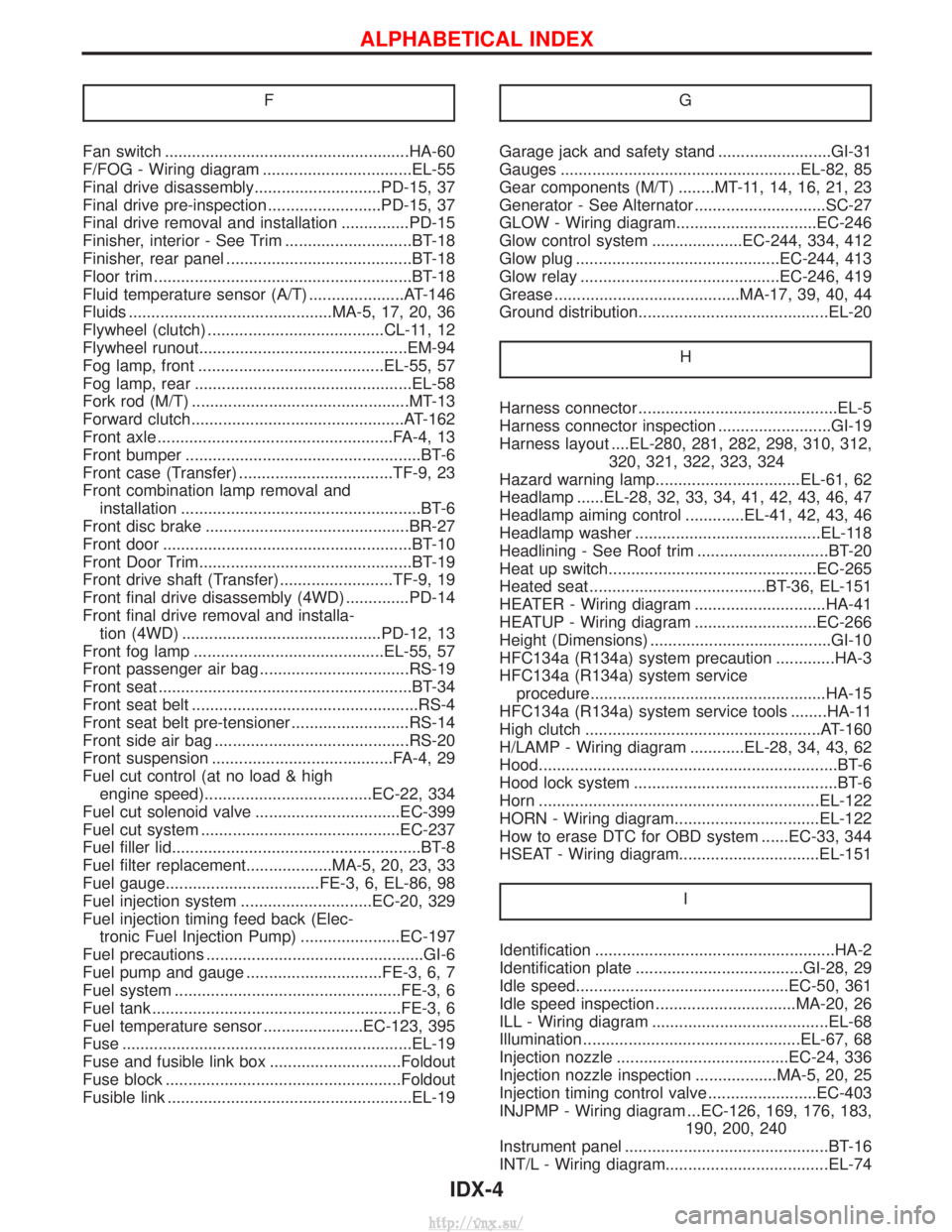
F
Fan switch ......................................................HA-60
F/FOG - Wiring diagram .................................EL-55
Final drive disassembly............................PD-15, 37
Final drive pre-inspection .........................PD-15, 37
Final drive removal and installation ...............PD-15
Finisher, interior - See Trim ............................BT-18
Finisher, rear panel .........................................BT-18
Floor trim .........................................................BT-18
Fluid temperature sensor (A/T) .....................AT-146
Fluids .............................................MA-5, 17, 20, 36
Flywheel (clutch) .......................................CL-11, 12
Flywheel runout..............................................EM-94
Fog lamp, front .........................................EL-55, 57
Fog lamp, rear ................................................EL-58
Fork rod (M/T) ................................................MT-13
Forward clutch...............................................AT-162
Front axle ....................................................FA-4, 13
Front bumper ....................................................BT-6
Front case (Transfer) ..................................TF-9, 23
Front combination lamp removal andinstallation .....................................................BT-6
Front disc brake .............................................BR-27
Front door .......................................................BT-10
Front Door Trim...............................................BT-19
Front drive shaft (Transfer) .........................TF-9, 19
Front final drive disassembly (4WD) ..............PD-14
Front final drive removal and installa- tion (4WD) ............................................PD-12, 13
Front fog lamp ..........................................EL-55, 57
Front passenger air bag .................................RS-19
Front seat ........................................................BT-34
Front seat belt ..................................................RS-4
Front seat belt pre-tensioner ..........................RS-14
Front side air bag ...........................................RS-20
Front suspension ........................................FA-4, 29
Fuel cut control (at no load & high engine speed).....................................EC-22, 334
Fuel cut solenoid valve ................................EC-399
Fuel cut system ............................................EC-237
Fuel filler lid.......................................................BT-8
Fuel filter replacement...................MA-5, 20, 23, 33
Fuel gauge..................................FE-3, 6, EL-86, 98
Fuel injection system .............................EC-20, 329
Fuel injection timing feed back (Elec- tronic Fuel Injection Pump) ......................EC-197
Fuel precautions ................................................GI-6
Fuel pump and gauge ..............................FE-3, 6, 7
Fuel system ..................................................FE-3, 6
Fuel tank .......................................................FE-3, 6
Fuel temperature sensor ......................EC-123, 395
Fuse ................................................................EL-19
Fuse and fusible link box .............................Foldout
Fuse block ....................................................Foldout
Fusible link ......................................................EL-19 GGarage jack and safety stand .........................GI-31
Gauges .....................................................EL-82, 85
Gear components (M/T) ........MT-11, 14, 16, 21, 23
Generator - See Alternator .............................SC-27
GLOW - Wiring diagram...............................EC-246
Glow control system ....................EC-244, 334, 412
Glow plug .............................................EC-244, 413
Glow relay ............................................EC-246, 419
Grease .........................................MA-17, 39, 40, 44
Ground distribution..........................................EL-20
H
Harness connector ............................................EL-5
Harness connector inspection .........................GI-19
Harness layout ....EL-280, 281, 282, 298, 310, 312,320, 321, 322, 323, 324
Hazard warning lamp................................EL-61, 62
Headlamp ......EL-28, 32, 33, 34, 41, 42, 43, 46, 47
Headlamp aiming control .............EL-41, 42, 43, 46
Headlamp washer .........................................EL-118
Headlining - See Roof trim .............................BT-20
Heat up switch..............................................EC-265
Heated seat .......................................BT-36, EL-151
HEATER - Wiring diagram .............................HA-41
HEATUP - Wiring diagram ...........................EC-266
Height (Dimensions) ........................................GI-10
HFC134a (R134a) system precaution .............HA-3
HFC134a (R134a) system service procedure....................................................HA-15
HFC134a (R134a) system service tools ........HA-11
High clutch ....................................................AT-160
H/LAMP - Wiring diagram ............EL-28, 34, 43, 62
Hood..................................................................BT-6
Hood lock system .............................................BT-6
Horn ..............................................................EL-122
HORN - Wiring diagram................................EL-122
How to erase DTC for OBD system ......EC-33, 344
HSEAT - Wiring diagram...............................EL-151
I
Identification .....................................................HA-2
Identification plate .....................................GI-28, 29
Idle speed...............................................EC-50, 361
Idle speed inspection ...............................MA-20, 26
ILL - Wiring diagram .......................................EL-68
Illumination ................................................EL-67, 68
Injection nozzle ......................................EC-24, 336
Injection nozzle inspection ..................MA-5, 20, 25
Injection timing control valve ........................EC-403
INJPMP - Wiring diagram ...EC-126, 169, 176, 183, 190, 200, 240
Instrument panel .............................................BT-16
INT/L - Wiring diagram....................................EL-74
ALPHABETICAL INDEX
IDX-4
http://vnx.su/