Manual de ecu NISSAN TERRANO 2004 Service Repair Manual
[x] Cancel search | Manufacturer: NISSAN, Model Year: 2004, Model line: TERRANO, Model: NISSAN TERRANO 2004Pages: 1833, PDF Size: 53.42 MB
Page 7 of 1833
insulation (either just before the harness connectors or for
the complete harness), for easy identification.
Precautions for NATS
NATS (Nissan Anti-Theft System)
NATS will immobilize the engine if someone tries to start it without
the registered key of NATS.
Both of the originally supplied ignition key IDs have been NATS
registered.
The NATS security indicator is located on the instrument panel. The
indicator blinks when the ignition switch is in ªOFFº or ªACCº posi-
tion. Therefore, NATS warns outsiders that the vehicle is equipped
with the anti-theft system.
IWhen NATS detects trouble, the malfunction indicator lamp
(MIL) blinks.
This blinking indicates that the anti-theft is not functioning, so
prompt service is required.
I If the malfunction indicator lamp comes on while the engine is
running, return the vehicle to the workshop before turning the
ignition switch ªOFFº.
Once the ignition switch is turned ªOFFº, the engine can not be
started.
I When servicing NATS (trouble diagnoses, system initialization
and additional registration of other NATS ignition key IDs) CON-
SULT-II hardware and CONSULT-II NATS software is neces-
sary.
Regarding the procedures of NATS initialization and NATS igni-
tion key ID registration, refer to CONSULT-II operation manual,
NATS.
Therefore, CONSULT-II NATS software (program card and
operation manual) must be kept strictly confidential to main-
tain the integrity of the anti-theft function.
I When servicing NATS (trouble diagnoses, system initialization
and additional registration of other NATS ignition key IDs), it
may be necessary to re-register original key identification.
Therefore, be sure to receive all keys from vehicle owner.
A maximum of five key IDs can be registered into NATS.
I When failing to start the engine first-time using the key of
NATS, starts as follows:
(1) Turn ignition key to ªOFFº.
(2) Wait approx. 5 seconds.
(3) Turn ignition key to ªSTARTº again while keeping the key
apart from any others on key-chain.
SGI916
PRECAUTIONS
Supplemental Restraint System (SRS) ªAIR
BAGº and ªSEAT BELT PRE-TENSIONERº
(Dual Air Bag System) (Cont'd)
GI-4
http://vnx.su/
Page 29 of 1833
Function and System Application
Diagnostictest mode Function ENGINE A/T Air bag ABS NATS*1
Self-diagnostic results Self-diagnostic results can be read and erased quickly. xxxxx
ECU discriminated No. Classification number of a replacement ECU can be
read to prevent an incorrect ECU from being installed. ÐÐxÐÐ
Data monitor Input/Output data in the ECM can be read. x xÐxÐ
Active test Diagnostic Test Mode in which CONSULT-II drives
some actuators apart from the ECMs and also shifts
some parameters in a specified range. xÐÐxÐ
ECU (ECM) part number ECU (ECM) part number can be read. x xÐxÐ
Control unit initialisation All registered ignition key IDs in NATS components can
be initialised and new IDs can be registered. ÐÐÐÐ x
Self-function check ECM checks its own NATS communication interface. ÐÐÐÐ x
x: Applicable
*1: NATS: Nissan Anti-Theft System
Nickel Metal Hydride Battery Replacement
CONSULT-II contains a nickel metal hydride battery. When replacing the battery obey the following:
WARNING:
Replace the nickel metal hydride battery with genuine CONSULT-II battery only. Use of another battery
may present a risk of fire or explosion. The battery may present a fire or chemical burn hazard if mis-
treated. Do not recharge, disassemble of dispose of in fire.
Keep the battery out of reach of children and discard used battery conforming to the local regulations.
Checking Equipment
When ordering this equipment, contact your NISSAN distributor.
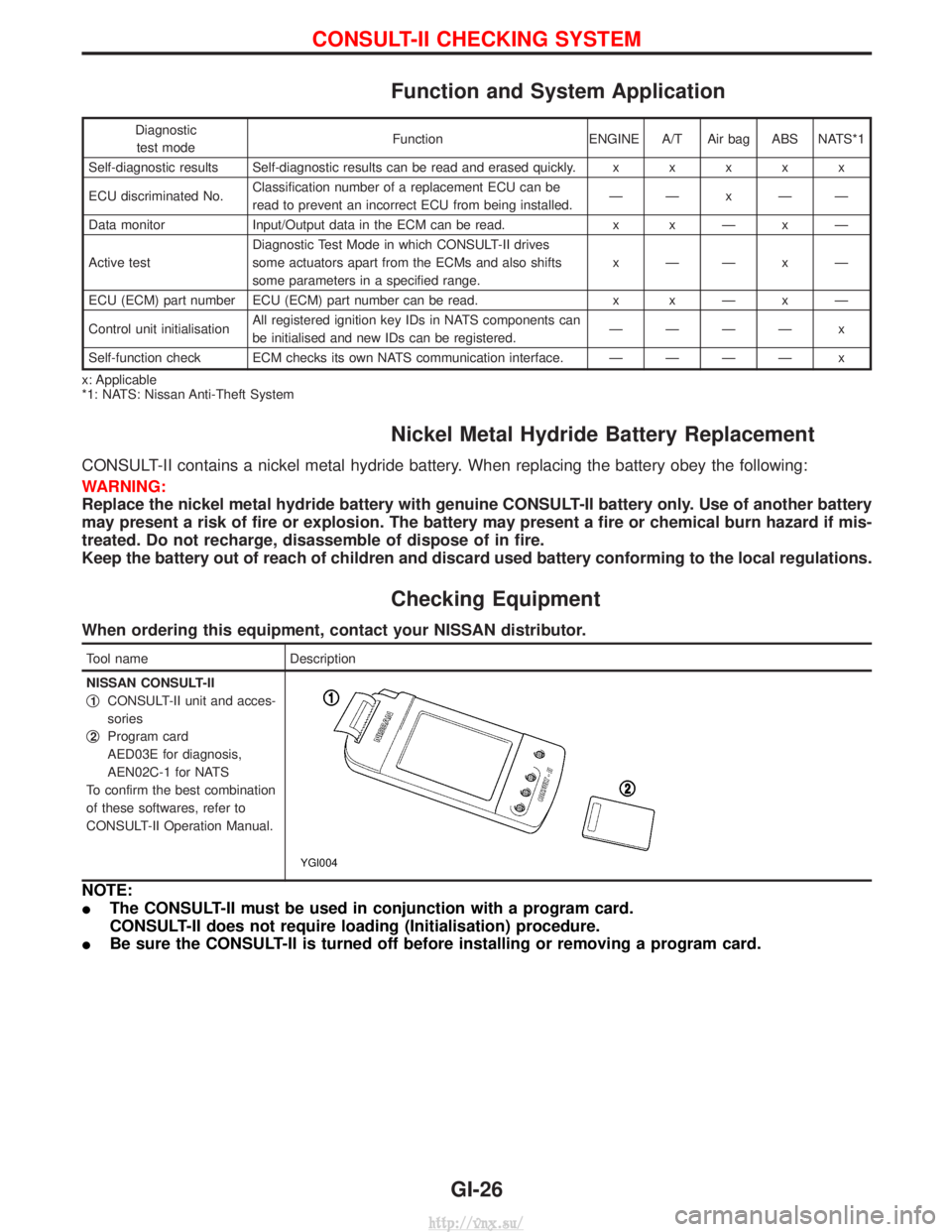
Tool name Description
NISSAN CONSULT-II
q
1CONSULT-II unit and acces-
sories
q
2Program card
AED03E for diagnosis,
AEN02C-1 for NATS
To confirm the best combination
of these softwares, refer to
CONSULT-II Operation Manual.
YGI004
NOTE:
I The CONSULT-II must be used in conjunction with a program card.
CONSULT-II does not require loading (Initialisation) procedure.
I Be sure the CONSULT-II is turned off before installing or removing a program card.
CONSULT-II CHECKING SYSTEM
GI-26
http://vnx.su/
Page 158 of 1833
Selection Procedure for Selective Part
Combination
LocationSelective part combination ItemMethod
Cylinder block - piston Piston and piston assembly
(Part No. is given to a piston and piston pin as a set.) Piston grade (Piston outer
diameter) Refer to ªSelective combination
chartº.
IIdentification grade stamped on each part represents initial
dimension of new part. This grade will not be applied to a
reused part.
I Measure correct dimensions of a reused or modified part, then
refer to ªSelective combination chartº in this manual to identify
the grade.
I Refer to the applicable pages for measurement method for
each part, standards for reuse, and selecting method for selec-
tive part combination.
Disassembly
1. Remove engine assembly from vehicle.
Refer to EM-63, ªENGINE REMOVALº.
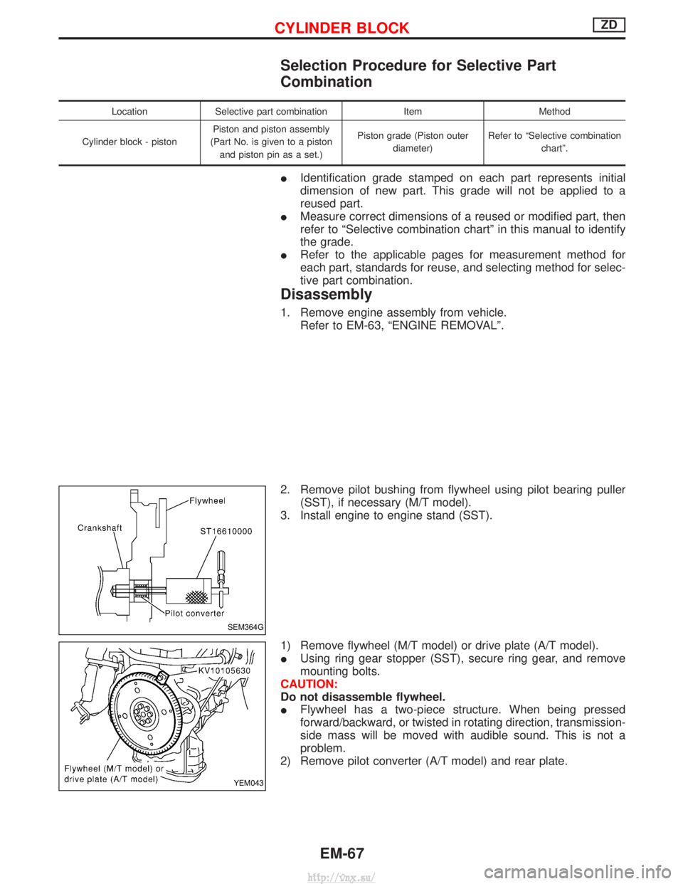
2. Remove pilot bushing from flywheel using pilot bearing puller (SST), if necessary (M/T model).
3. Install engine to engine stand (SST).
1) Remove flywheel (M/T model) or drive plate (A/T model).
I Using ring gear stopper (SST), secure ring gear, and remove
mounting bolts.
CAUTION:
Do not disassemble flywheel.
I Flywheel has a two-piece structure. When being pressed
forward/backward, or twisted in rotating direction, transmission-
side mass will be moved with audible sound. This is not a
problem.
2) Remove pilot converter (A/T model) and rear plate.
SEM364G
YEM043
CYLINDER BLOCKZD
EM-67
http://vnx.su/
Page 309 of 1833
IIf the battery is disconnected, the emission-related diagnostic information will be lost after approx.
24 hours.
I Erasing the emission-related diagnostic information using CONSULT-II is easier and quicker than
switching the diagnostic test mode using the data link connector.
NATS (Nissan Anti-Theft System)
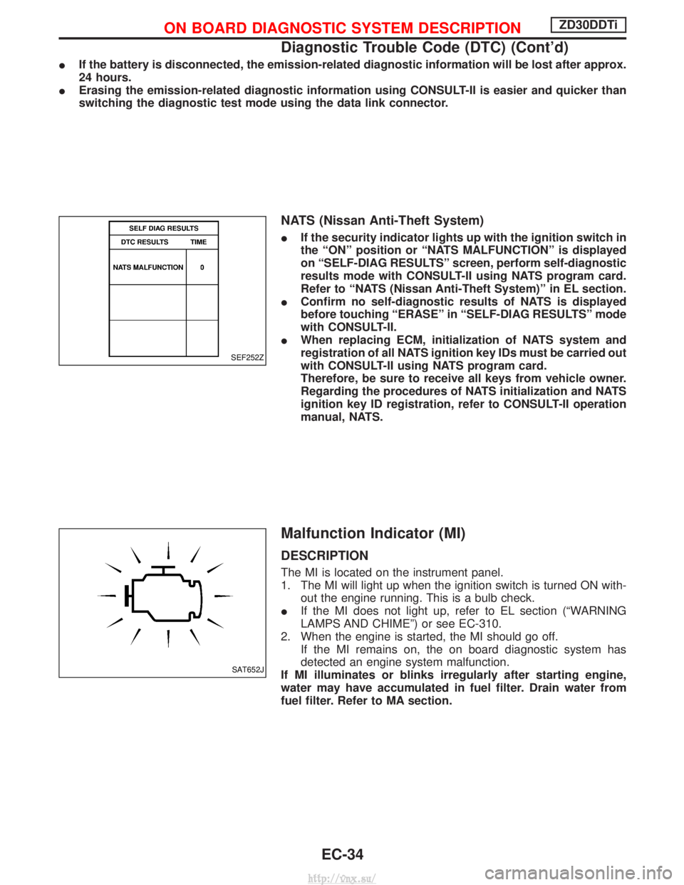
IIf the security indicator lights up with the ignition switch in
the ªONº position or ªNATS MALFUNCTIONº is displayed
on ªSELF-DIAG RESULTSº screen, perform self-diagnostic
results mode with CONSULT-II using NATS program card.
Refer to ªNATS (Nissan Anti-Theft System)º in EL section.
I Confirm no self-diagnostic results of NATS is displayed
before touching ªERASEº in ªSELF-DIAG RESULTSº mode
with CONSULT-II.
I When replacing ECM, initialization of NATS system and
registration of all NATS ignition key IDs must be carried out
with CONSULT-II using NATS program card.
Therefore, be sure to receive all keys from vehicle owner.
Regarding the procedures of NATS initialization and NATS
ignition key ID registration, refer to CONSULT-II operation
manual, NATS.
Malfunction Indicator (MI)
DESCRIPTION
The MI is located on the instrument panel.
1. The MI will light up when the ignition switch is turned ON with-
out the engine running. This is a bulb check.
I If the MI does not light up, refer to EL section (ªWARNING
LAMPS AND CHIMEº) or see EC-310.
2. When the engine is started, the MI should go off. If the MI remains on, the on board diagnostic system has
detected an engine system malfunction.
If MI illuminates or blinks irregularly after starting engine,
water may have accumulated in fuel filter. Drain water from
fuel filter. Refer to MA section.
SEF252Z
SAT652J
ON BOARD DIAGNOSTIC SYSTEM DESCRIPTIONZD30DDTi
Diagnostic Trouble Code (DTC) (Cont'd)
EC-34
http://vnx.su/
Page 833 of 1833
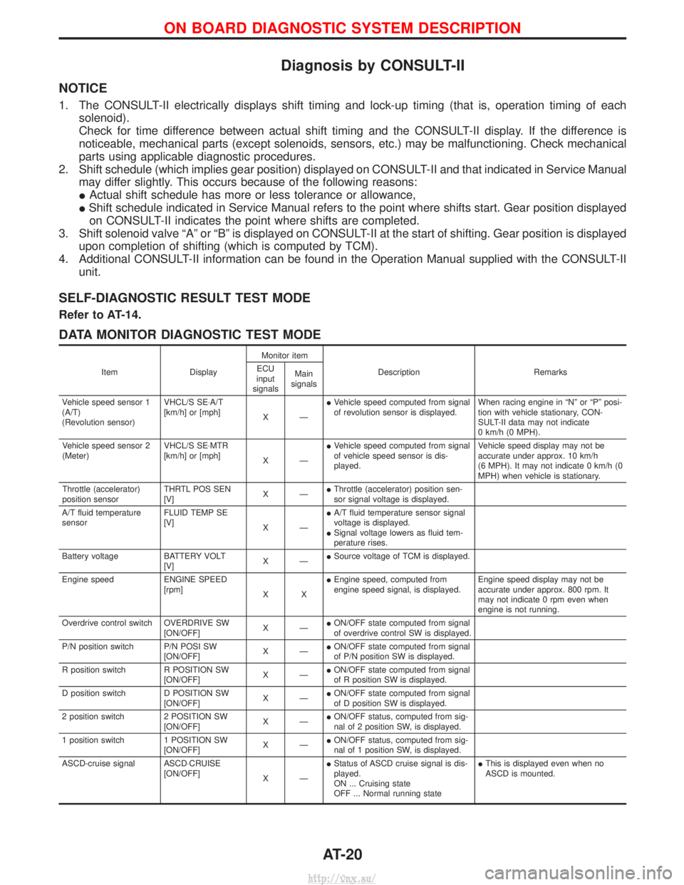
Diagnosis by CONSULT-II
NOTICE
1. The CONSULT-II electrically displays shift timing and lock-up timing (that is, operation timing of eachsolenoid).
Check for time difference between actual shift timing and the CONSULT-II display. If the difference is
noticeable, mechanical parts (except solenoids, sensors, etc.) may be malfunctioning. Check mechanical
parts using applicable diagnostic procedures.
2. Shift schedule (which implies gear position) displayed on CONSULT-II and that indicated in Service Manual may differ slightly. This occurs because of the following reasons:
IActual shift schedule has more or less tolerance or allowance,
I Shift schedule indicated in Service Manual refers to the point where shifts start. Gear position displayed
on CONSULT-II indicates the point where shifts are completed.
3. Shift solenoid valve ªAº or ªBº is displayed on CONSULT-II at the start of shifting. Gear position is displayed upon completion of shifting (which is computed by TCM).
4. Additional CONSULT-II information can be found in the Operation Manual supplied with the CONSULT-II unit.
SELF-DIAGNOSTIC RESULT TEST MODE
Refer to AT-14.
DATA MONITOR DIAGNOSTIC TEST MODE
Item DisplayMonitor item
Description Remarks
ECU
input
signals Main
signals
Vehicle speed sensor 1
(A/T)
(Revolution sensor) VHCL/S SE×A/T
[km/h] or [mph]
XÐI
Vehicle speed computed from signal
of revolution sensor is displayed. When racing engine in ªNº or ªPº posi-
tion with vehicle stationary, CON-
SULT-II data may not indicate
0 km/h (0 MPH).
Vehicle speed sensor 2
(Meter) VHCL/S SE×MTR
[km/h] or [mph]
XÐI
Vehicle speed computed from signal
of vehicle speed sensor is dis-
played. Vehicle speed display may not be
accurate under approx. 10 km/h
(6 MPH). It may not indicate 0 km/h (0
MPH) when vehicle is stationary.
Throttle (accelerator)
position sensor THRTL POS SEN
[V]
XÐI
Throttle (accelerator) position sen-
sor signal voltage is displayed.
A/T fluid temperature
sensor FLUID TEMP SE
[V]
XÐI
A/T fluid temperature sensor signal
voltage is displayed.
I Signal voltage lowers as fluid tem-
perature rises.
Battery voltage BATTERY VOLT [V]XÐI
Source voltage of TCM is displayed.
Engine speed ENGINE SPEED [rpm]XXI
Engine speed, computed from
engine speed signal, is displayed. Engine speed display may not be
accurate under approx. 800 rpm. It
may not indicate 0 rpm even when
engine is not running.
Overdrive control switch OVERDRIVE SW [ON/OFF]XÐI
ON/OFF state computed from signal
of overdrive control SW is displayed.
P/N position switch P/N POSI SW [ON/OFF]XÐI
ON/OFF state computed from signal
of P/N position SW is displayed.
R position switch R POSITION SW [ON/OFF]XÐI
ON/OFF state computed from signal
of R position SW is displayed.
D position switch D POSITION SW [ON/OFF]XÐI
ON/OFF state computed from signal
of D position SW is displayed.
2 position switch 2 POSITION SW [ON/OFF]XÐI
ON/OFF status, computed from sig-
nal of 2 position SW, is displayed.
1 position switch 1 POSITION SW [ON/OFF]XÐI
ON/OFF status, computed from sig-
nal of 1 position SW, is displayed.
ASCD-cruise signal ASCD×CRUISE [ON/OFF]XÐI
Status of ASCD cruise signal is dis-
played.
ON ... Cruising state
OFF ... Normal running state I
This is displayed even when no
ASCD is mounted.
ON BOARD DIAGNOSTIC SYSTEM DESCRIPTION
AT-20
http://vnx.su/
Page 1303 of 1833
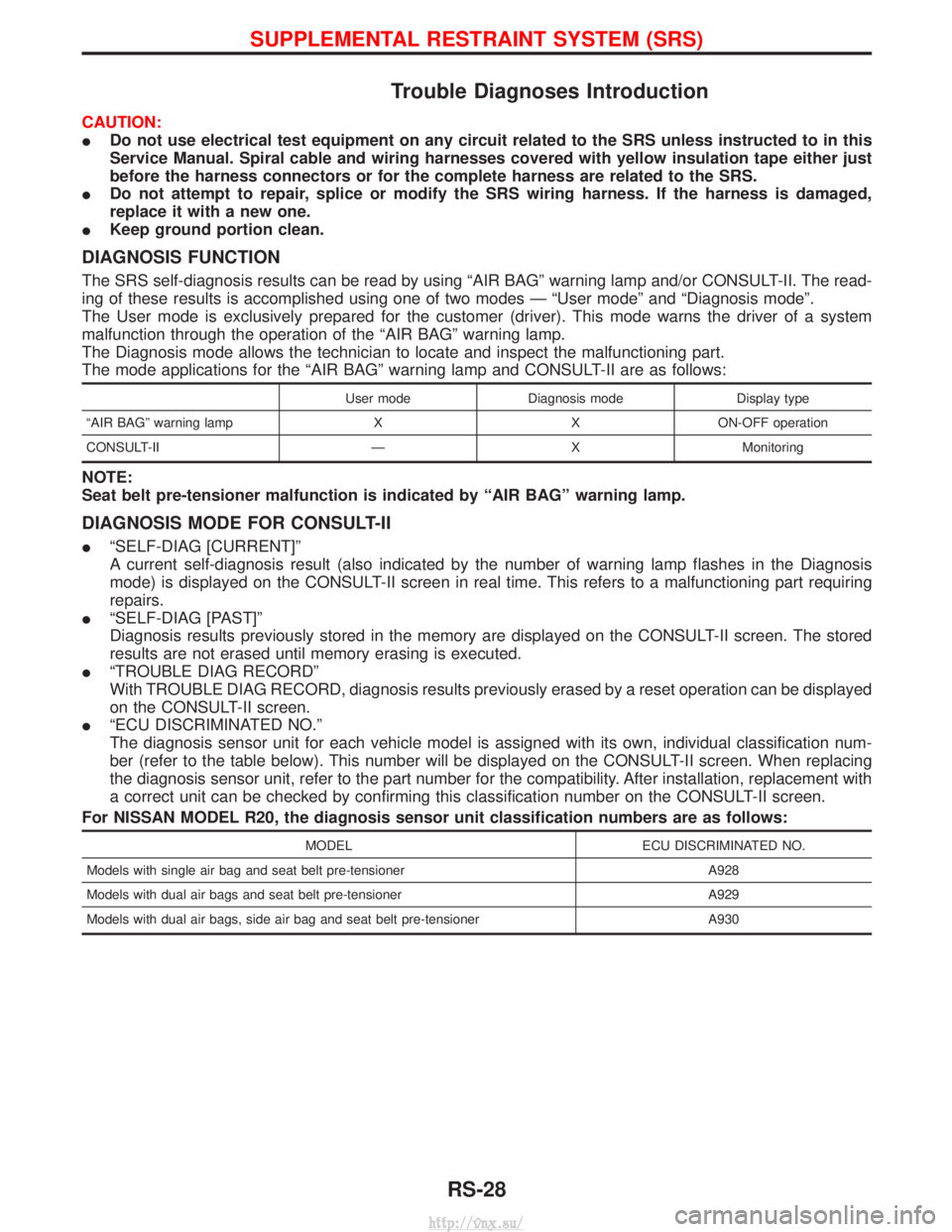
Trouble Diagnoses Introduction
CAUTION:
IDo not use electrical test equipment on any circuit related to the SRS unless instructed to in this
Service Manual. Spiral cable and wiring harnesses covered with yellow insulation tape either just
before the harness connectors or for the complete harness are related to the SRS.
I Do not attempt to repair, splice or modify the SRS wiring harness. If the harness is damaged,
replace it with a new one.
I Keep ground portion clean.
DIAGNOSIS FUNCTION
The SRS self-diagnosis results can be read by using ªAIR BAGº warning lamp and/or CONSULT-II. The read-
ing of these results is accomplished using one of two modes Ð ªUser modeº and ªDiagnosis modeº.
The User mode is exclusively prepared for the customer (driver). This mode warns the driver of a system
malfunction through the operation of the ªAIR BAGº warning lamp.
The Diagnosis mode allows the technician to locate and inspect the malfunctioning part.
The mode applications for the ªAIR BAGº warning lamp and CONSULT-II are as follows:
User mode Diagnosis mode Display type
ªAIR BAGº warning lamp X X ON-OFF operation
CONSULT-II Ð X Monitoring
NOTE:
Seat belt pre-tensioner malfunction is indicated by ªAIR BAGº warning lamp.
DIAGNOSIS MODE FOR CONSULT-II
I ªSELF-DIAG [CURRENT]º
A current self-diagnosis result (also indicated by the number of warning lamp flashes in the Diagnosis
mode) is displayed on the CONSULT-II screen in real time. This refers to a malfunctioning part requiring
repairs.
I ªSELF-DIAG [PAST]º
Diagnosis results previously stored in the memory are displayed on the CONSULT-II screen. The stored
results are not erased until memory erasing is executed.
I ªTROUBLE DIAG RECORDº
With TROUBLE DIAG RECORD, diagnosis results previously erased by a reset operation can be displayed
on the CONSULT-II screen.
I ªECU DISCRIMINATED NO.º
The diagnosis sensor unit for each vehicle model is assigned with its own, individual classification num-
ber (refer to the table below). This number will be displayed on the CONSULT-II screen. When replacing
the diagnosis sensor unit, refer to the part number for the compatibility. After installation, replacement with
a correct unit can be checked by confirming this classification number on the CONSULT-II screen.
For NISSAN MODEL R20, the diagnosis sensor unit classification numbers are as follows:
MODEL ECU DISCRIMINATED NO.
Models with single air bag and seat belt pre-tensioner A928
Models with dual air bags and seat belt pre-tensioner A929
Models with dual air bags, side air bag and seat belt pre-tensioner A930
SUPPLEMENTAL RESTRAINT SYSTEM (SRS)
RS-28
http://vnx.su/
Page 1412 of 1833
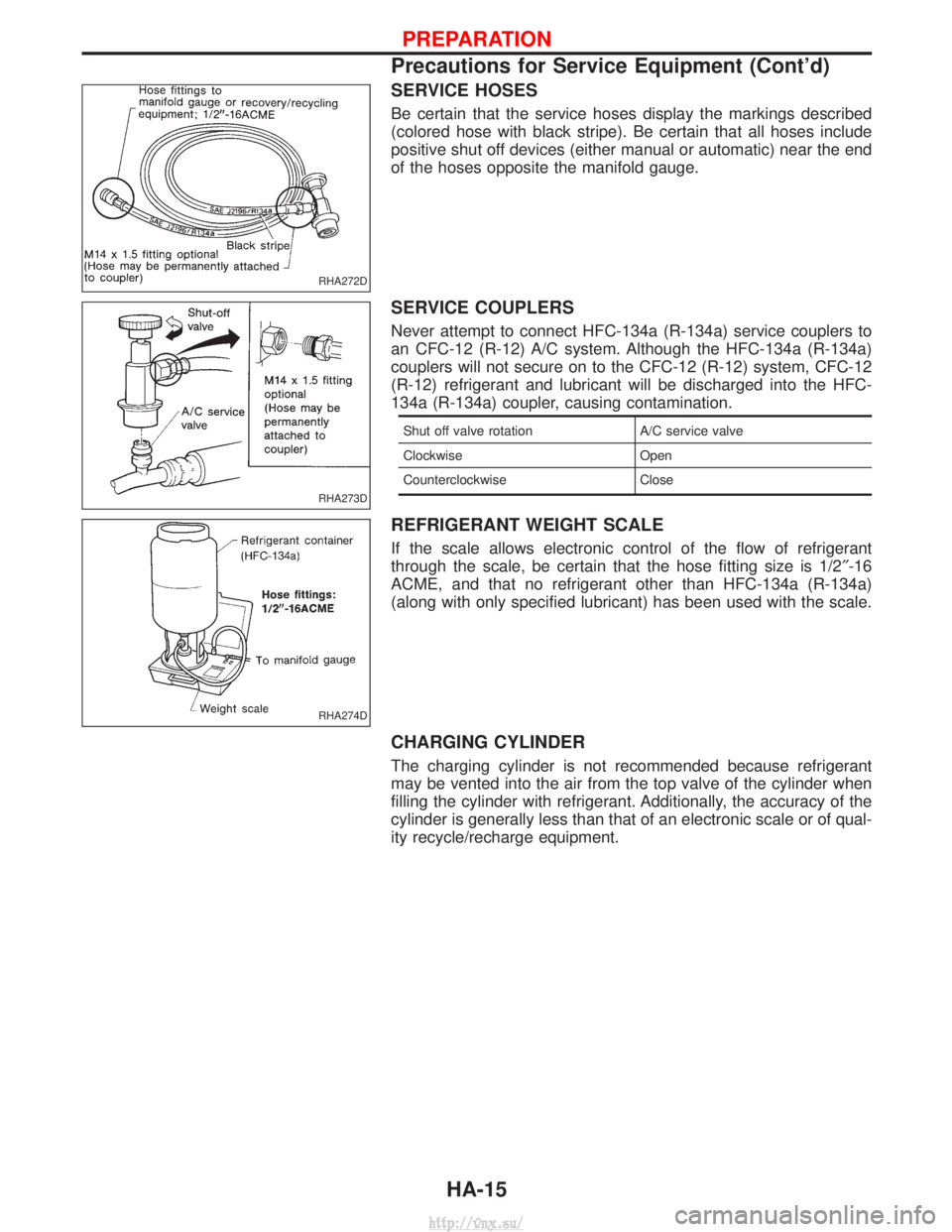
SERVICE HOSES
Be certain that the service hoses display the markings described
(colored hose with black stripe). Be certain that all hoses include
positive shut off devices (either manual or automatic) near the end
of the hoses opposite the manifold gauge.
SERVICE COUPLERS
Never attempt to connect HFC-134a (R-134a) service couplers to
an CFC-12 (R-12) A/C system. Although the HFC-134a (R-134a)
couplers will not secure on to the CFC-12 (R-12) system, CFC-12
(R-12) refrigerant and lubricant will be discharged into the HFC-
134a (R-134a) coupler, causing contamination.
Shut off valve rotationA/C service valve
Clockwise Open
Counterclockwise Close
REFRIGERANT WEIGHT SCALE
If the scale allows electronic control of the flow of refrigerant
through the scale, be certain that the hose fitting size is 1/2 ²-16
ACME, and that no refrigerant other than HFC-134a (R-134a)
(along with only specified lubricant) has been used with the scale.
CHARGING CYLINDER
The charging cylinder is not recommended because refrigerant
may be vented into the air from the top valve of the cylinder when
filling the cylinder with refrigerant. Additionally, the accuracy of the
cylinder is generally less than that of an electronic scale or of qual-
ity recycle/recharge equipment.
RHA272D
RHA273D
RHA274D
PREPARATION
Precautions for Service Equipment (Cont'd)
HA-15
http://vnx.su/
Page 1627 of 1833
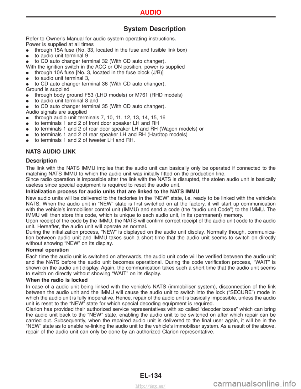
System Description
Refer to Owner's Manual for audio system operating instructions.
Power is supplied at all times
Ithrough 15A fuse (No. 33, located in the fuse and fusible link box)
I to audio unit terminal 9
I to CD auto changer terminal 32 (With CD auto changer).
With the ignition switch in the ACC or ON position, power is supplied
I through 10A fuse [No. 3, located in the fuse block (J/B)]
I to audio unit terminal 3,
I to CD auto changer terminal 36 (With CD auto changer).
Ground is supplied
I through body ground F53 (LHD models) or M761 (RHD models)
I to audio unit terminal 8 and
I to CD auto changer terminal 35 (With CD auto changer).
Audio signals are supplied
I through audio unit terminals 7, 10, 11, 12, 13, 14, 15, 16
I to terminals 1 and 2 of front door speaker LH and RH
I to terminals 1 and 2 of rear door speaker LH and RH (Wagon models) or
I to terminals 1 and 2 of rear speaker LH and RH (Hardtop models)
I to terminals 1 and 2 of tweeter LH and RH.
NATS AUDIO LINK
Description
The link with the NATS IMMU implies that the audio unit can basically only be operated if connected to the
matching NATS IMMU to which the audio unit was initially fitted on the production line.
Since radio operation is impossible after the link with the NATS is disrupted, the stolen audio unit is basically
useless since special equipment is required to reset the audio unit.
Initialization process for audio units that are linked to the NATS IMMU
New audio units will be delivered to the factories in the ªNEWº state, i.e. ready to be linked with the vehicle's
NATS. When the audio unit in ªNEWº state is first switched on at the factory, it will start up communication
with the vehicle's immobiliser control unit (IMMU) and send a code (the ªaudio unit Codeº) to the IMMU. The
IMMU will then store this code, which is unique to each audio unit, in its (permanent) memory.
Upon receipt of the code by the IMMU, the NATS will confirm correct receipt of the audio unit code to the audio
unit. Hereafter, the audio unit will operate as normal.
During the initialization process, ªNEWº is displayed on the audio unit display. Normally though, communica-
tion between audio unit and IMMU takes such a short time that the audio unit seems to switch on directly
without showing ªNEWº on its display.
Normal operation
Each time the audio unit is switched on afterwards, the audio unit code will be verified between the audio unit
and the NATS before the audio unit becomes operational. During the code verification process, ªWAITº is
shown on the audio unit display. Again, the communication takes such a short time that the audio unit seems
to switch on directly without showing ªWAITº on its display.
When the radio is locked
In case of a audio unit being linked with the vehicle's NATS (immobiliser system), disconnection of the link
between the audio unit and the IMMU will cause the audio unit to switch into the lock (ªSECUREº) mode in
which the audio unit is fully inoperative. Hence, repair of the audio unit is basically impossible, unless the audio
unit is reset to the ªNEWº state for which special decoding equipment is required.
Clarion has provided their authorized service representatives with so called ªdecoder boxesº which can bring
the audio unit back to the ªNEWº state, enabling the audio unit to be switched on after which repair can be
carried out. Subsequently, when the repaired audio unit is delivered to the final user again, it will be in the
ªNEWº state as to enable re-linking the audio unit to the vehicle's immobiliser system. As a result of the above,
repair of the audio unit can only be done by an authorized Clarion representative.
AUDIO
EL-134
http://vnx.su/
Page 1628 of 1833
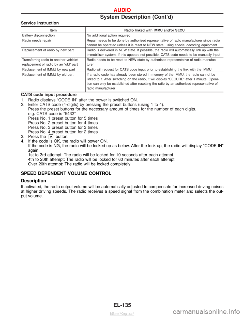
Service instruction
ItemRadio linked with IMMU and/or SECU
Battery disconnection No additional action required
Radio needs repair Repair needs to be done by authorised representative of radio manufacturer since radio cannot be operated unless it is reset to NEW state, using special decoding equipment
Replacement of radio by new part Radio is delivered in NEW state. If possible, the radio will automatically link up with the immobiliser system. If this appears not possible, CATS code needs to be manually input
Transferring radio to another vehicle/
replacement of radio by an ªoldº part Radio needs to be reset to NEW state by authorised representative of radio manufac-
turer
Replacement of IMMU by new part Radio will request for CATS code input prior to establishing the link with the IMMU
Replacement of IMMU by old part If a radio code has already been stored in memory of the IMMU, the radio cannot be linked to it. After switching on the radio, it will display ªSECUREº after 1 minute. Opera-
tion can only be established after resetting the ratio by an authorised representative of
radio manufacturer
CATS code input procedure
1. Radio displays ªCODE INº after the power is switched ON.
2. Enter CATS code (4-digits) by pressing the preset buttons (using 1 to 4).Press the preset buttons for the necessary amount of times for the number of each digits.
e.g. CATS code is ª5432º
Press No. 1 preset button for 5 times
Press No. 2 preset button for 4 times
Press No. 3 preset button for 3 times
Press No. 4 preset button for 2 times
3. Press the
button.
4. If the code is OK, the radio will power ON. If the code is NG, the radio will be locked up as below. After the lock up, the radio will display ªCODE INº
again.
1st to 3rd attempt: The radio will be locked for 10 seconds after each attempt
4th to 20th attempt: The radio will be locked for 60 minutes after each attempt
Over 20th attempt: The radio will be locked completely
SPEED DEPENDENT VOLUME CONTROL
Description
If activated, the radio output volume will be automatically adjusted to compensate for increased driving noises
at higher driving speeds. The radio receives a speed signal from the combination meter and selects the out-
put volume.
AUDIO
System Description (Cont'd)
EL-135
http://vnx.su/
Page 1715 of 1833
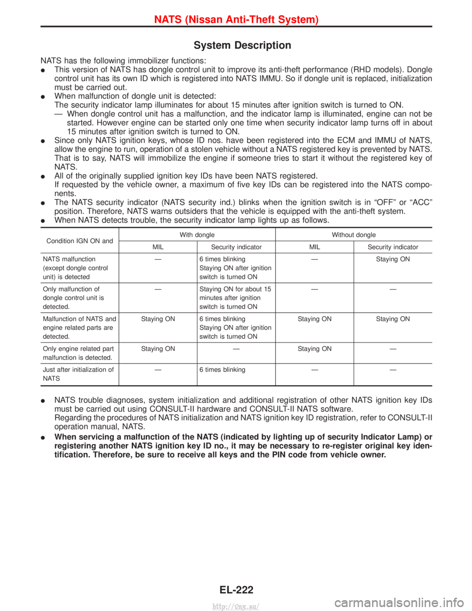
System Description
NATS has the following immobilizer functions:
IThis version of NATS has dongle control unit to improve its anti-theft performance (RHD models). Dongle
control unit has its own ID which is registered into NATS IMMU. So if dongle unit is replaced, initialization
must be carried out.
I When malfunction of dongle unit is detected:
The security indicator lamp illuminates for about 15 minutes after ignition switch is turned to ON.
Ð When dongle control unit has a malfunction, and the indicator lamp is illuminated, engine can not be
started. However engine can be started only one time when security indicator lamp turns off in about
15 minutes after ignition switch is turned to ON.
I Since only NATS ignition keys, whose ID nos. have been registered into the ECM and IMMU of NATS,
allow the engine to run, operation of a stolen vehicle without a NATS registered key is prevented by NATS.
That is to say, NATS will immobilize the engine if someone tries to start it without the registered key of
NATS.
I All of the originally supplied ignition key IDs have been NATS registered.
If requested by the vehicle owner, a maximum of five key IDs can be registered into the NATS compo-
nents.
I The NATS security indicator (NATS security ind.) blinks when the ignition switch is in ªOFFº or ªACCº
position. Therefore, NATS warns outsiders that the vehicle is equipped with the anti-theft system.
I When NATS detects trouble, the security indicator lamp lights up as follows.
Condition IGN ON and With dongle Without dongle
MIL Security indicator MIL Security indicator
NATS malfunction
(except dongle control
unit) is detected Ð
6 times blinking
Staying ON after ignition
switch is turned ON Ð
Staying ON
Only malfunction of
dongle control unit is
detected. Ð Staying ON for about 15
minutes after ignition
switch is turned ON ÐÐ
Malfunction of NATS and
engine related parts are
detected. Staying ON 6 times blinking
Staying ON after ignition
switch is turned ON Staying ON Staying ON
Only engine related part
malfunction is detected. Staying ON Ð Staying ON Ð
Just after initialization of
NATS Ð 6 times blinking Ð Ð
I
NATS trouble diagnoses, system initialization and additional registration of other NATS ignition key IDs
must be carried out using CONSULT-II hardware and CONSULT-II NATS software.
Regarding the procedures of NATS initialization and NATS ignition key ID registration, refer to CONSULT-II
operation manual, NATS.
I When servicing a malfunction of the NATS (indicated by lighting up of security Indicator Lamp) or
registering another NATS ignition key ID no., it may be necessary to re-register original key iden-
tification. Therefore, be sure to receive all keys and the PIN code from vehicle owner.
NATS (Nissan Anti-Theft System)
EL-222
http://vnx.su/