clock NISSAN TERRANO 2004 Service Repair Manual
[x] Cancel search | Manufacturer: NISSAN, Model Year: 2004, Model line: TERRANO, Model: NISSAN TERRANO 2004Pages: 1833, PDF Size: 53.42 MB
Page 44 of 1833
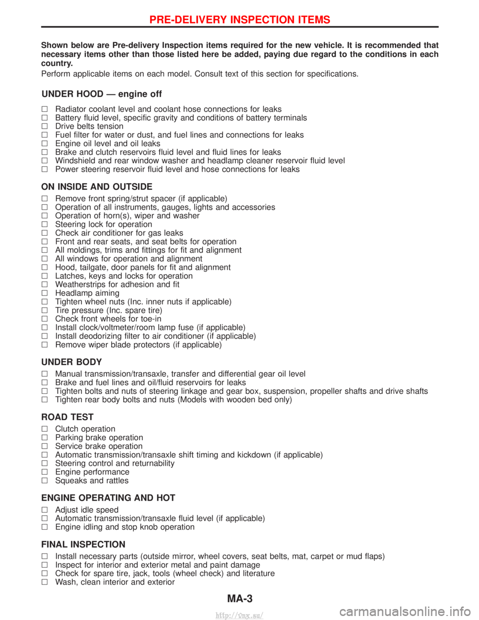
Shown below are Pre-delivery Inspection items required for the new vehicle. It is recommended that
necessary items other than those listed here be added, paying due regard to the conditions in each
country.
Perform applicable items on each model. Consult text of this section for specifications.
UNDER HOOD Ð engine off
lRadiator coolant level and coolant hose connections for leaks
l Battery fluid level, specific gravity and conditions of battery terminals
l Drive belts tension
l Fuel filter for water or dust, and fuel lines and connections for leaks
l Engine oil level and oil leaks
l Brake and clutch reservoirs fluid level and fluid lines for leaks
l Windshield and rear window washer and headlamp cleaner reservoir fluid level
l Power steering reservoir fluid level and hose connections for leaks
ON INSIDE AND OUTSIDE
lRemove front spring/strut spacer (if applicable)
l Operation of all instruments, gauges, lights and accessories
l Operation of horn(s), wiper and washer
l Steering lock for operation
l Check air conditioner for gas leaks
l Front and rear seats, and seat belts for operation
l All moldings, trims and fittings for fit and alignment
l All windows for operation and alignment
l Hood, tailgate, door panels for fit and alignment
l Latches, keys and locks for operation
l Weatherstrips for adhesion and fit
l Headlamp aiming
l Tighten wheel nuts (Inc. inner nuts if applicable)
l Tire pressure (Inc. spare tire)
l Check front wheels for toe-in
l Install clock/voltmeter/room lamp fuse (if applicable)
l Install deodorizing filter to air conditioner (if applicable)
l Remove wiper blade protectors (if applicable)
UNDER BODY
lManual transmission/transaxle, transfer and differential gear oil level
l Brake and fuel lines and oil/fluid reservoirs for leaks
l Tighten bolts and nuts of steering linkage and gear box, suspension, propeller shafts and drive shafts
l Tighten rear body bolts and nuts (Models with wooden bed only)
ROAD TEST
lClutch operation
l Parking brake operation
l Service brake operation
l Automatic transmission/transaxle shift timing and kickdown (if applicable)
l Steering control and returnability
l Engine performance
l Squeaks and rattles
ENGINE OPERATING AND HOT
lAdjust idle speed
l Automatic transmission/transaxle fluid level (if applicable)
l Engine idling and stop knob operation
FINAL INSPECTION
lInstall necessary parts (outside mirror, wheel covers, seat belts, mat, carpet or mud flaps)
l Inspect for interior and exterior metal and paint damage
l Check for spare tire, jack, tools (wheel check) and literature
l Wash, clean interior and exterior
PRE-DELIVERY INSPECTION ITEMS
MA-3
http://vnx.su/
Page 118 of 1833
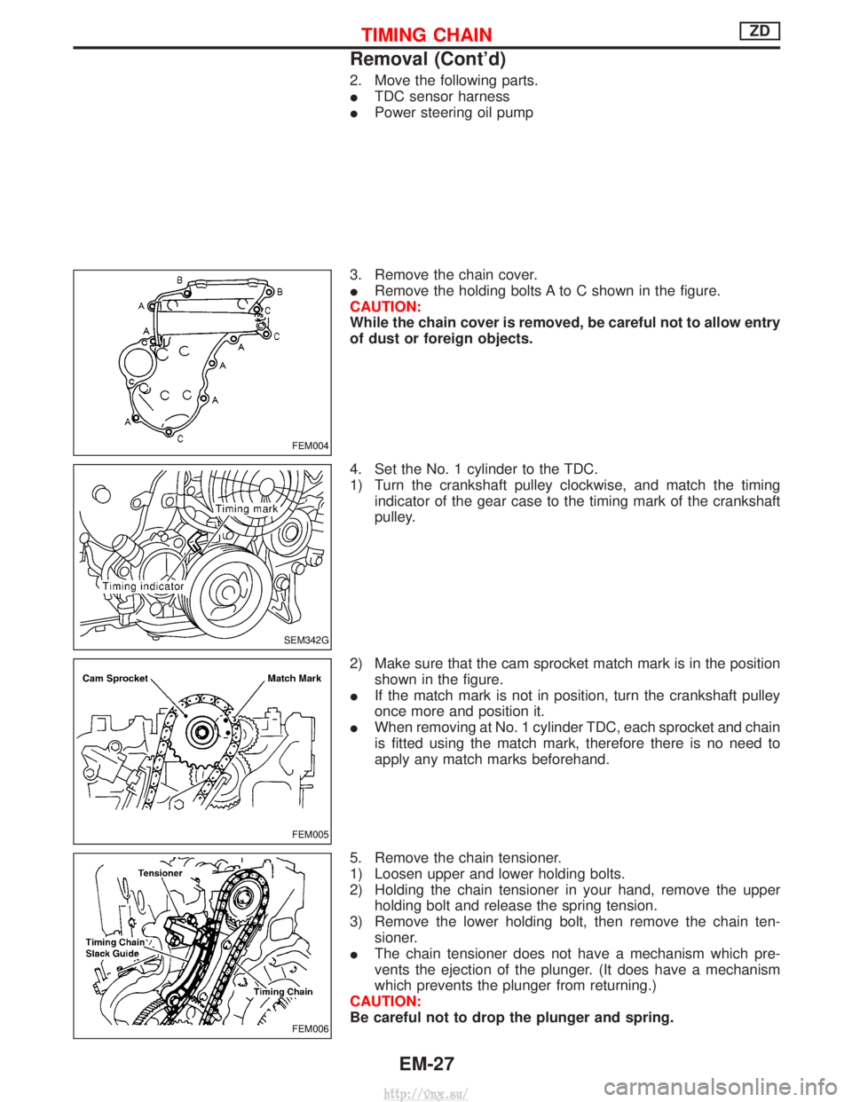
2. Move the following parts.
ITDC sensor harness
I Power steering oil pump
3. Remove the chain cover.
I Remove the holding bolts A to C shown in the figure.
CAUTION:
While the chain cover is removed, be careful not to allow entry
of dust or foreign objects.
4. Set the No. 1 cylinder to the TDC.
1) Turn the crankshaft pulley clockwise, and match the timing indicator of the gear case to the timing mark of the crankshaft
pulley.
2) Make sure that the cam sprocket match mark is in the position shown in the figure.
I If the match mark is not in position, turn the crankshaft pulley
once more and position it.
I When removing at No. 1 cylinder TDC, each sprocket and chain
is fitted using the match mark, therefore there is no need to
apply any match marks beforehand.
5. Remove the chain tensioner.
1) Loosen upper and lower holding bolts.
2) Holding the chain tensioner in your hand, remove the upper holding bolt and release the spring tension.
3) Remove the lower holding bolt, then remove the chain ten- sioner.
I The chain tensioner does not have a mechanism which pre-
vents the ejection of the plunger. (It does have a mechanism
which prevents the plunger from returning.)
CAUTION:
Be careful not to drop the plunger and spring.
FEM004
SEM342G
FEM005
FEM006
TIMING CHAINZD
Removal (Cont'd)
EM-27
http://vnx.su/
Page 126 of 1833
Inspection
IWhen the camshaft or parts in connection with valves are
removed or replaced, and a fault has occurred (poor starting,
idling, or other faults) due to the misadjustment of the valve
clearance, inspect as follows.
I Inspect and adjust when the engine is cool (at normal tempera-
ture).
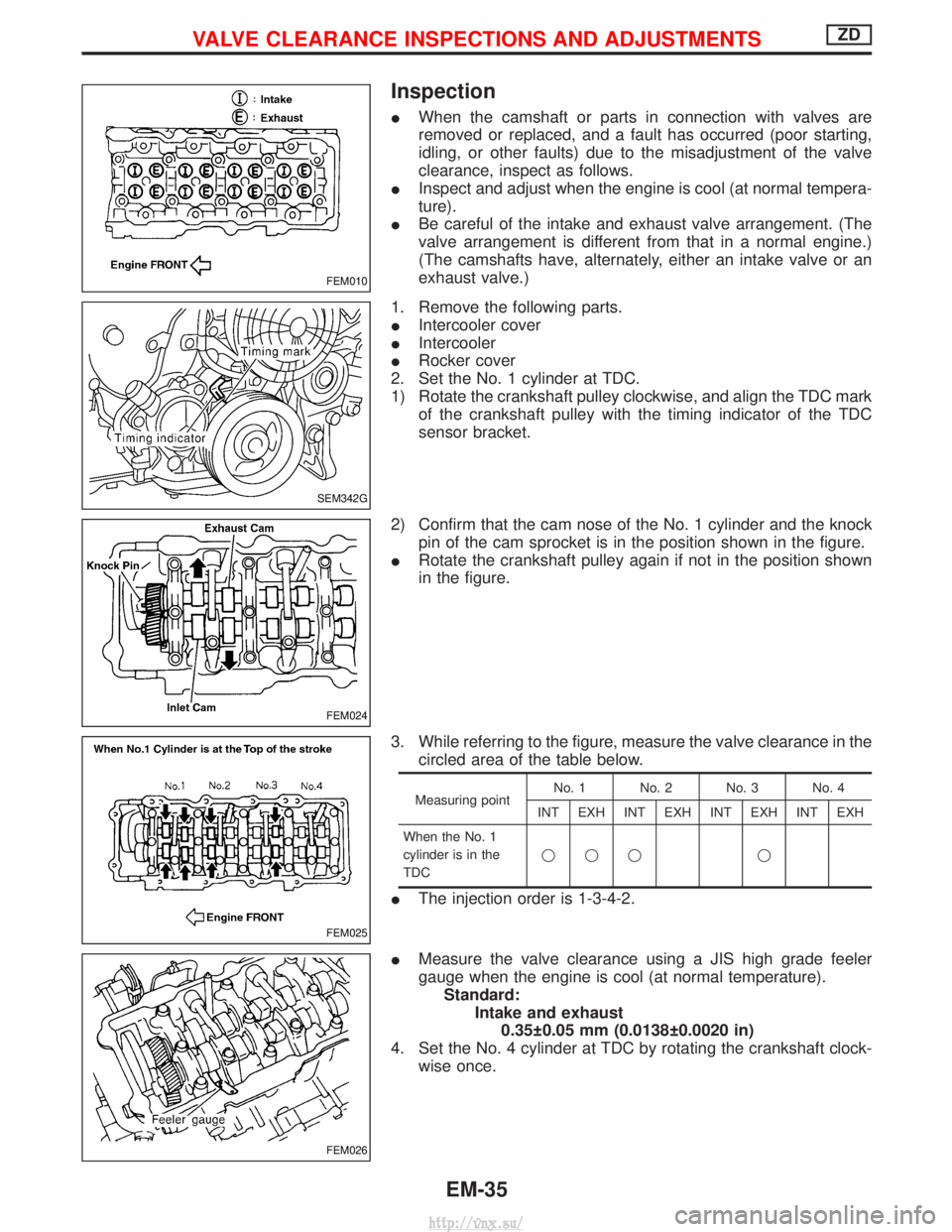
I Be careful of the intake and exhaust valve arrangement. (The
valve arrangement is different from that in a normal engine.)
(The camshafts have, alternately, either an intake valve or an
exhaust valve.)
1. Remove the following parts.
I Intercooler cover
I Intercooler
I Rocker cover
2. Set the No. 1 cylinder at TDC.
1) Rotate the crankshaft pulley clockwise, and align the TDC mark of the crankshaft pulley with the timing indicator of the TDC
sensor bracket.
2) Confirm that the cam nose of the No. 1 cylinder and the knock pin of the cam sprocket is in the position shown in the figure.
I Rotate the crankshaft pulley again if not in the position shown
in the figure.
3. While referring to the figure, measure the valve clearance in the circled area of the table below.
Measuring point No. 1 No. 2 No. 3 No. 4
INT EXH INT EXH INT EXH INT EXH
When the No. 1
cylinder is in the
TDC qqq q
I
The injection order is 1-3-4-2.
I Measure the valve clearance using a JIS high grade feeler
gauge when the engine is cool (at normal temperature).
Standard: Intake and exhaust0.35 0.05 mm (0.0138 0.0020 in)
4. Set the No. 4 cylinder at TDC by rotating the crankshaft clock- wise once.
FEM010
SEM342G
FEM024
FEM025
FEM026
VALVE CLEARANCE INSPECTIONS AND ADJUSTMENTSZD
EM-35
http://vnx.su/
Page 206 of 1833

2. Install cylinder head.
ICylinder head identification mark
3. Apply oil to threaded portion and seat surface of bolts and tighten cylinder head bolts using Tool.
CAUTION:
I Tightening procedure
1st: Tighten bolts to 39 - 44 N×m (4.0 - 4.5 kg-m, 29 - 33 ft-lb)
2nd: Tighten bolts to 54 - 59 N ×m
(5.5 - 6.0 kg-m, 40 - 43 ft-lb)
3rd: (1) Mark exhaust side of cylinder head and cylin-der head bolts with paint as shown.
(2) Turn all bolts 90 10 degrees clockwise.
(3) Check that paint mark of each bolt is facing the front of the vehicle.
4. Apply engine oil and install push rods.
5. Install rocker shaft assembly. Adjust intake and exhaust valve clearance carefully.
Refer to MA section in order to accomplish valve adjustment.
NEM179
SEM641B
SEM580C
SEM642B
CYLINDER HEADTD27Ti
Installation (Cont'd)
EM-115
http://vnx.su/
Page 300 of 1833
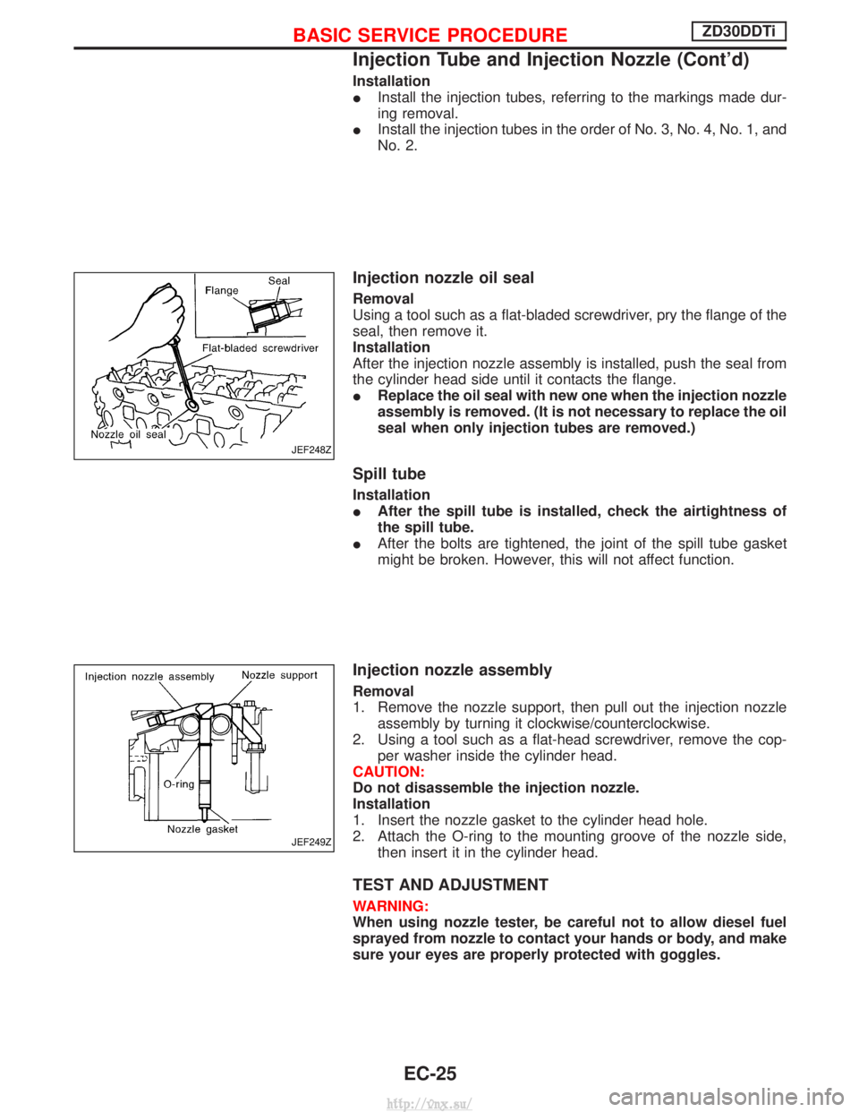
Installation
IInstall the injection tubes, referring to the markings made dur-
ing removal.
I Install the injection tubes in the order of No. 3, No. 4, No. 1, and
No. 2.
Injection nozzle oil seal
Removal
Using a tool such as a flat-bladed screwdriver, pry the flange of the
seal, then remove it.
Installation
After the injection nozzle assembly is installed, push the seal from
the cylinder head side until it contacts the flange.
IReplace the oil seal with new one when the injection nozzle
assembly is removed. (It is not necessary to replace the oil
seal when only injection tubes are removed.)
Spill tube
Installation
IAfter the spill tube is installed, check the airtightness of
the spill tube.
I After the bolts are tightened, the joint of the spill tube gasket
might be broken. However, this will not affect function.
Injection nozzle assembly
Removal
1. Remove the nozzle support, then pull out the injection nozzle
assembly by turning it clockwise/counterclockwise.
2. Using a tool such as a flat-head screwdriver, remove the cop- per washer inside the cylinder head.
CAUTION:
Do not disassemble the injection nozzle.
Installation
1. Insert the nozzle gasket to the cylinder head hole.
2. Attach the O-ring to the mounting groove of the nozzle side, then insert it in the cylinder head.
TEST AND ADJUSTMENT
WARNING:
When using nozzle tester, be careful not to allow diesel fuel
sprayed from nozzle to contact your hands or body, and make
sure your eyes are properly protected with goggles.
JEF248Z
JEF249Z
BASIC SERVICE PROCEDUREZD30DDTi
Injection Tube and Injection Nozzle (Cont'd)
EC-25
http://vnx.su/
Page 303 of 1833
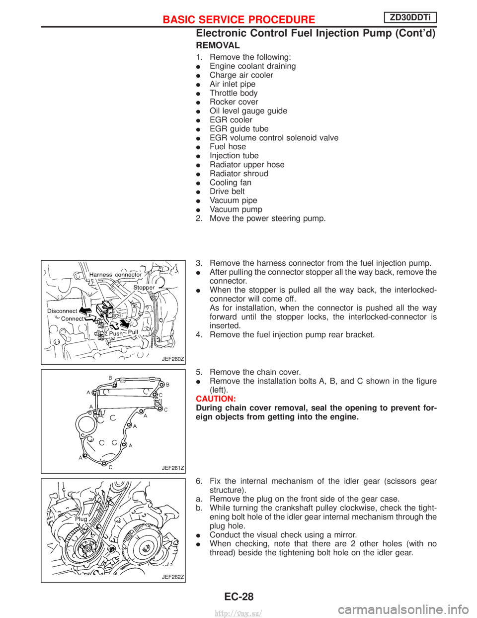
REMOVAL
1. Remove the following:
IEngine coolant draining
I Charge air cooler
I Air inlet pipe
I Throttle body
I Rocker cover
I Oil level gauge guide
I EGR cooler
I EGR guide tube
I EGR volume control solenoid valve
I Fuel hose
I Injection tube
I Radiator upper hose
I Radiator shroud
I Cooling fan
I Drive belt
I Vacuum pipe
I Vacuum pump
2. Move the power steering pump.
3. Remove the harness connector from the fuel injection pump.
I After pulling the connector stopper all the way back, remove the
connector.
I When the stopper is pulled all the way back, the interlocked-
connector will come off.
As for installation, when the connector is pushed all the way
forward until the stopper locks, the interlocked-connector is
inserted.
4. Remove the fuel injection pump rear bracket.
5. Remove the chain cover.
I Remove the installation bolts A, B, and C shown in the figure
(left).
CAUTION:
During chain cover removal, seal the opening to prevent for-
eign objects from getting into the engine.
6. Fix the internal mechanism of the idler gear (scissors gear structure).
a. Remove the plug on the front side of the gear case.
b. While turning the crankshaft pulley clockwise, check the tight- ening bolt hole of the idler gear internal mechanism through the
plug hole.
I Conduct the visual check using a mirror.
I When checking, note that there are 2 other holes (with no
thread) beside the tightening bolt hole on the idler gear.
JEF260Z
JEF261Z
JEF262Z
BASIC SERVICE PROCEDUREZD30DDTi
Electronic Control Fuel Injection Pump (Cont'd)
EC-28
http://vnx.su/
Page 637 of 1833
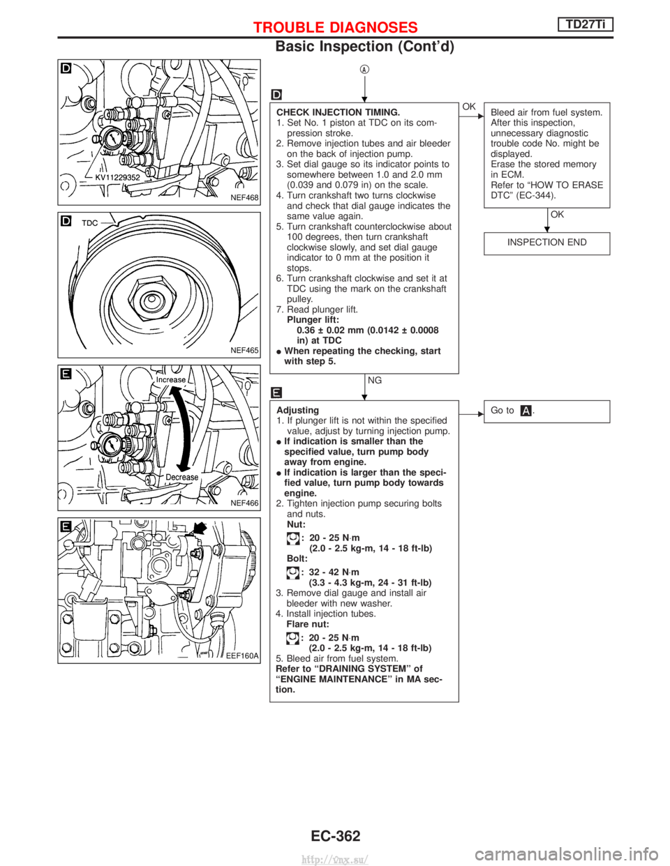
qA
CHECK INJECTION TIMING.
1. Set No. 1 piston at TDC on its com-pression stroke.
2. Remove injection tubes and air bleeder on the back of injection pump.
3. Set dial gauge so its indicator points to somewhere between 1.0 and 2.0 mm
(0.039 and 0.079 in) on the scale.
4. Turn crankshaft two turns clockwise and check that dial gauge indicates the
same value again.
5. Turn crankshaft counterclockwise about 100 degrees, then turn crankshaft
clockwise slowly, and set dial gauge
indicator to 0 mm at the position it
stops.
6. Turn crankshaft clockwise and set it at TDC using the mark on the crankshaft
pulley.
7. Read plunger lift. Plunger lift:0.36 0.02 mm (0.0142 0.0008
in) at TDC
I When repeating the checking, start
with step 5.
NG
EOK
Bleed air from fuel system.
After this inspection,
unnecessary diagnostic
trouble code No. might be
displayed.
Erase the stored memory
in ECM.
Refer to ªHOW TO ERASE
DTCº (EC-344).
OK
INSPECTION END
Adjusting
1. If plunger lift is not within the specified value, adjust by turning injection pump.
I If indication is smaller than the
specified value, turn pump body
away from engine.
I If indication is larger than the speci-
fied value, turn pump body towards
engine.
2. Tighten injection pump securing bolts and nuts.
Nut:
: 20-25N ×m
(2.0 - 2.5 kg-m, 14 - 18 ft-lb)
Bolt:
: 32-42N ×m
(3.3 - 4.3 kg-m, 24 - 31 ft-lb)
3. Remove dial gauge and install air bleeder with new washer.
4. Install injection tubes. Flare nut:
: 20-25N ×m
(2.0 - 2.5 kg-m, 14 - 18 ft-lb)
5. Bleed air from fuel system.
Refer to ªDRAINING SYSTEMº of
ªENGINE MAINTENANCEº in MA sec-
tion.
EGo to.
NEF468
NEF465
NEF466
EEF160A
H
H
H
TROUBLE DIAGNOSESTD27Ti
Basic Inspection (Cont'd)
EC-362
http://vnx.su/
Page 941 of 1833
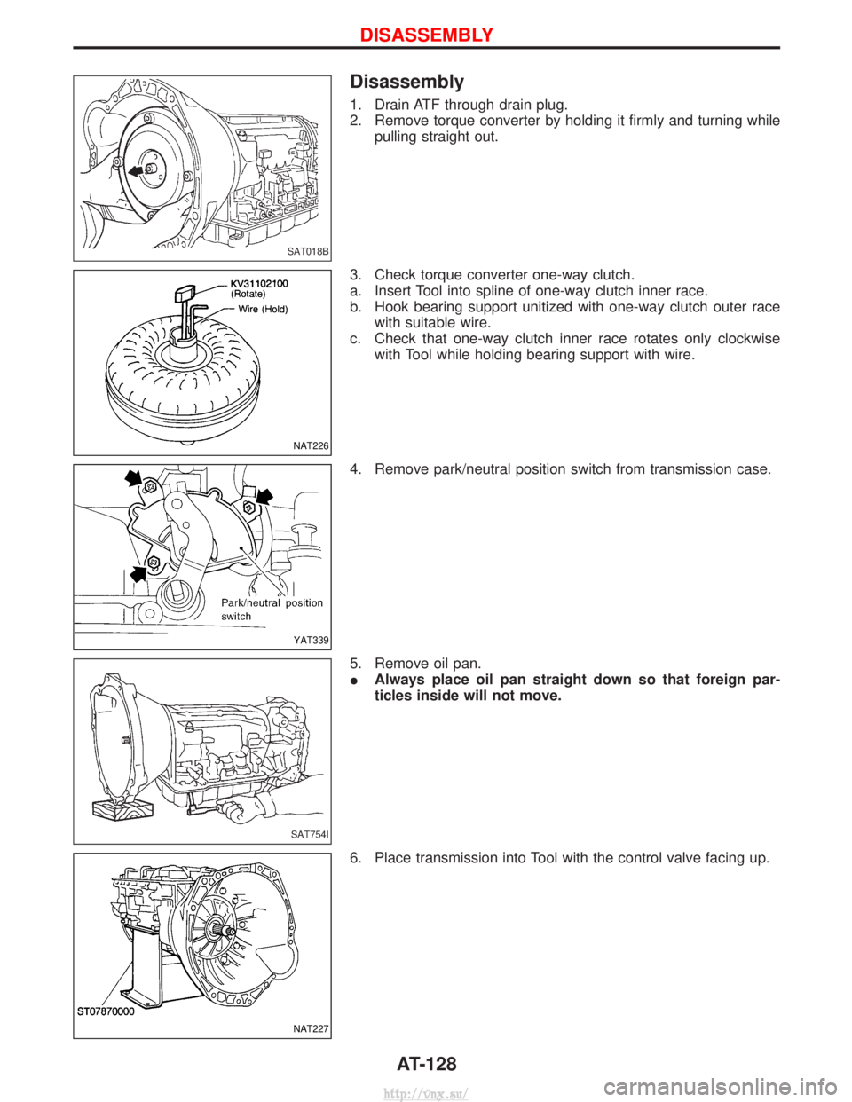
Disassembly
1. Drain ATF through drain plug.
2. Remove torque converter by holding it firmly and turning whilepulling straight out.
3. Check torque converter one-way clutch.
a. Insert Tool into spline of one-way clutch inner race.
b. Hook bearing support unitized with one-way clutch outer race with suitable wire.
c. Check that one-way clutch inner race rotates only clockwise with Tool while holding bearing support with wire.
4. Remove park/neutral position switch from transmission case.
5. Remove oil pan.
I Always place oil pan straight down so that foreign par-
ticles inside will not move.
6. Place transmission into Tool with the control valve facing up.
SAT018B
NAT226
YAT339
SAT754I
NAT227
DISASSEMBLY
AT-128
http://vnx.su/
Page 988 of 1833
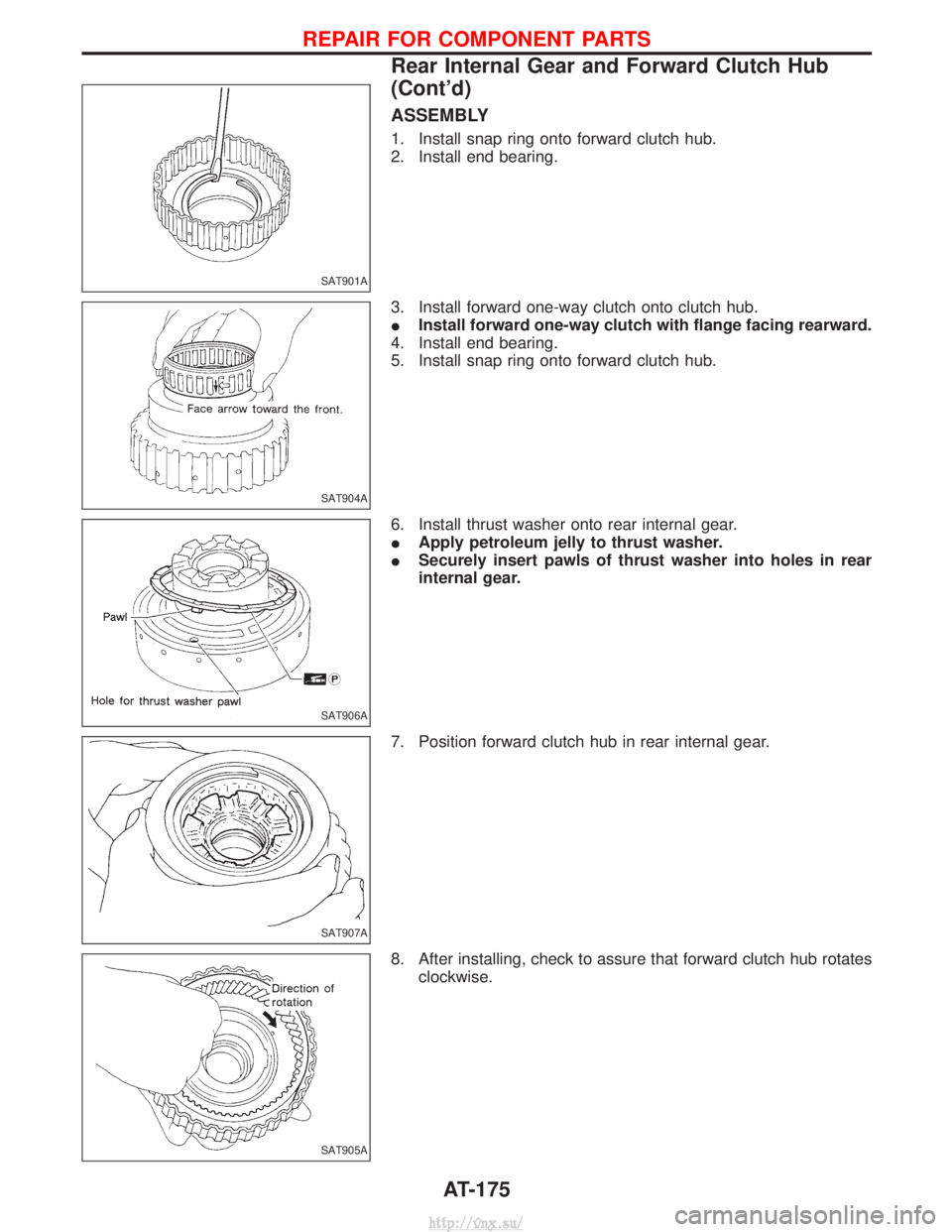
ASSEMBLY
1. Install snap ring onto forward clutch hub.
2. Install end bearing.
3. Install forward one-way clutch onto clutch hub.
IInstall forward one-way clutch with flange facing rearward.
4. Install end bearing.
5. Install snap ring onto forward clutch hub.
6. Install thrust washer onto rear internal gear.
I Apply petroleum jelly to thrust washer.
I Securely insert pawls of thrust washer into holes in rear
internal gear.
7. Position forward clutch hub in rear internal gear.
8. After installing, check to assure that forward clutch hub rotates clockwise.
SAT901A
SAT904A
SAT906A
SAT907A
SAT905A
REPAIR FOR COMPONENT PARTS
Rear Internal Gear and Forward Clutch Hub
(Cont'd)
AT-175
http://vnx.su/
Page 997 of 1833
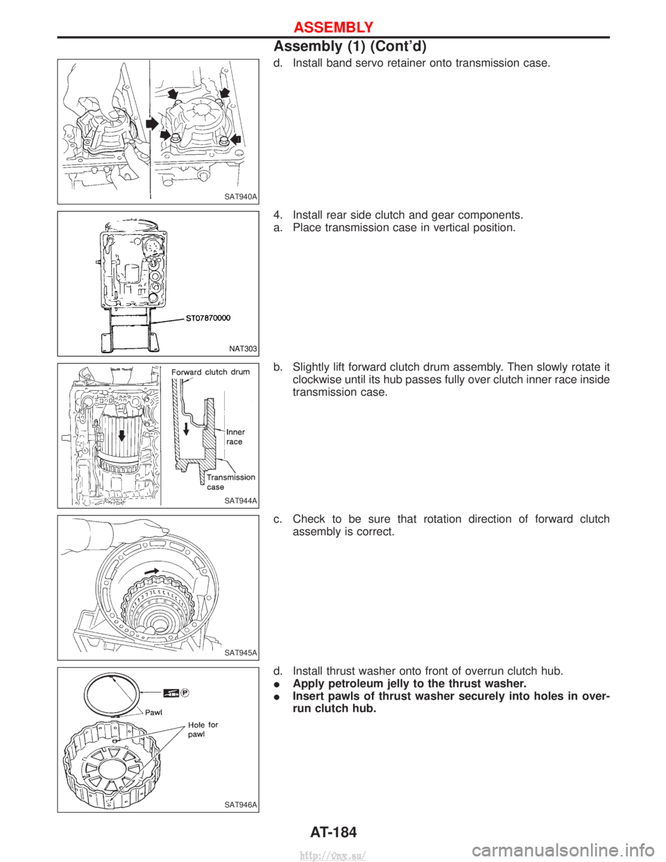
d. Install band servo retainer onto transmission case.
4. Install rear side clutch and gear components.
a. Place transmission case in vertical position.
b. Slightly lift forward clutch drum assembly. Then slowly rotate itclockwise until its hub passes fully over clutch inner race inside
transmission case.
c. Check to be sure that rotation direction of forward clutch assembly is correct.
d. Install thrust washer onto front of overrun clutch hub.
I Apply petroleum jelly to the thrust washer.
I Insert pawls of thrust washer securely into holes in over-
run clutch hub.
SAT940A
NAT303
SAT944A
SAT945A
SAT946A
ASSEMBLY
Assembly (1) (Cont'd)
AT-184
http://vnx.su/