glove box NISSAN TERRANO 2004 Service Repair Manual
[x] Cancel search | Manufacturer: NISSAN, Model Year: 2004, Model line: TERRANO, Model: NISSAN TERRANO 2004Pages: 1833, PDF Size: 53.42 MB
Page 85 of 1833
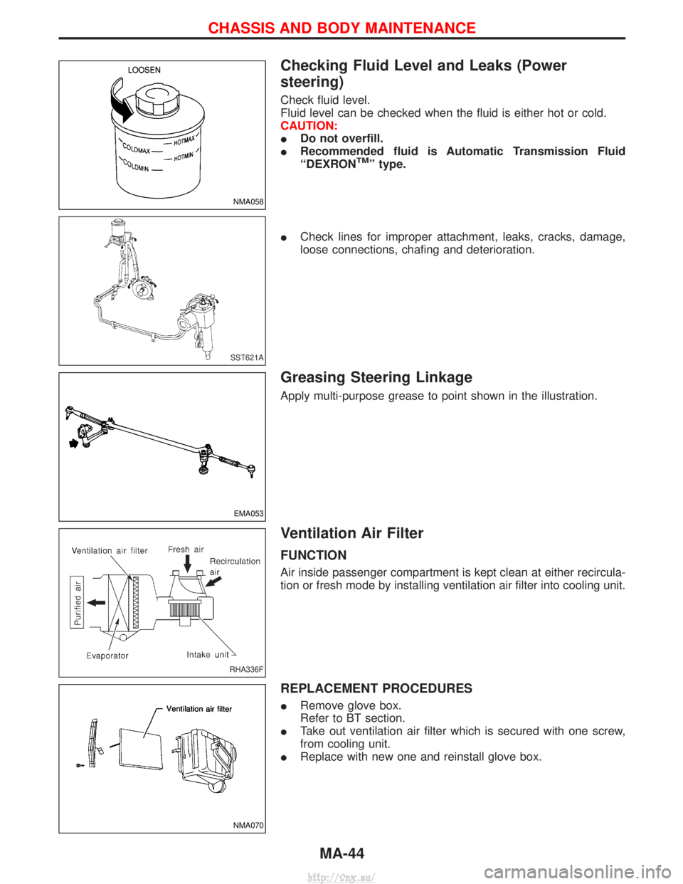
Checking Fluid Level and Leaks (Power
steering)
Check fluid level.
Fluid level can be checked when the fluid is either hot or cold.
CAUTION:
IDo not overfill.
I Recommended fluid is Automatic Transmission Fluid
ªDEXRON
TMº type.
I Check lines for improper attachment, leaks, cracks, damage,
loose connections, chafing and deterioration.
Greasing Steering Linkage
Apply multi-purpose grease to point shown in the illustration.
Ventilation Air Filter
FUNCTION
Air inside passenger compartment is kept clean at either recircula-
tion or fresh mode by installing ventilation air filter into cooling unit.
REPLACEMENT PROCEDURES
IRemove glove box.
Refer to BT section.
I Take out ventilation air filter which is secured with one screw,
from cooling unit.
I Replace with new one and reinstall glove box.
NMA058
SST621A
EMA053
RHA336F
NMA070
CHASSIS AND BODY MAINTENANCE
MA-44
http://vnx.su/
Page 1294 of 1833
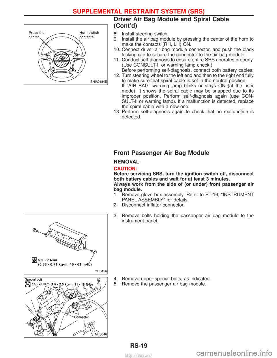
8. Install steering switch.
9. Install the air bag module by pressing the center of the horn tomake the contacts (RH, LH) ON.
10. Connect driver air bag module connector, and push the black locking clip to secure the connector to the air bag module.
11. Conduct self-diagnosis to ensure entire SRS operates properly. (Use CONSULT-II or warning lamp check.)
Before performing self-diagnosis, connect both battery cables.
12. Turn steering wheel to the left end and then to the right end fully to make sure that spiral cable is set in the neutral position.
If ªAIR BAGº warning lamp blinks or stays ON (at the user
mode), it shows the spiral cable may be snapped due to its
improper position. Perform self-diagnosis again (use CON-
SULT-II or warning lamp). If a malfunction is detected, replace
the spiral cable with a new one.
13. Perform self-diagnosis again to check that no malfunction is detected.
Front Passenger Air Bag Module
REMOVAL
CAUTION:
Before servicing SRS, turn the ignition switch off, disconnect
both battery cables and wait for at least 3 minutes.
Always work from the side of (or under) front passenger air
bag module.
1. Remove glove box assembly. Refer to BT-16, ªINSTRUMENTPANEL ASSEMBLYº for details.
2. Disconnect inflator connector.
3. Remove bolts holding the passenger air bag module to the instrument panel.
4. Remove upper special bolts, as indicated.
5. Remove the passenger air bag module.
SHIA0184E
YRS126
NRS046
SUPPLEMENTAL RESTRAINT SYSTEM (SRS)
Driver Air Bag Module and Spiral Cable
(Cont'd)
RS-19
http://vnx.su/
Page 1295 of 1833
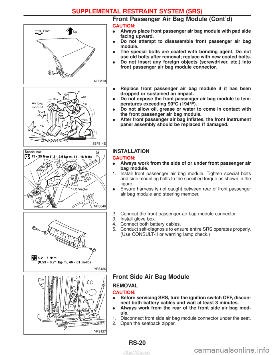
CAUTION:
IAlways place front passenger air bag module with pad side
facing upward.
I Do not attempt to disassemble front passenger air bag
module.
I The special bolts are coated with bonding agent. Do not
use old bolts after removal; replace with new coated bolts.
I Do not insert any foreign objects (screwdriver, etc.) into
front passenger air bag module connector.
I Replace front passenger air bag module if it has been
dropped or sustained an impact.
I Do not expose the front passenger air bag module to tem-
peratures exceeding 90ÉC (194ÉF).
I Do not allow oil, grease or water to come in contact with
the front passenger air bag module.
I After front passenger air bag inflates, the front instrument
panel assembly should be replaced if damaged.
INSTALLATION
CAUTION:
IAlways work from the side of or under front passenger air
bag module.
1. Install front passenger air bag module. Tighten special bolts and side mounting bolts to the specified torque as shown in the
figure.
I Ensure harness is not caught between rear of front passenger
air bag module and steering member.
2. Connect the front passenger air bag module connector.
3. Install glove box.
4. Connect both battery cables.
5. Conduct self-diagnosis to ensure entire SRS operates properly. (Use CONSULT-II or warning lamp check.)
Front Side Air Bag Module
REMOVAL
CAUTION:
IBefore servicing SRS, turn the ignition switch OFF, discon-
nect both battery cables and wait at least 3 minutes.
I Always work from the rear of the front side air bag mod-
ule.
1. Disconnect front side air bag module connector under the seat.
2. Open the seatback zipper.
NRS110
SBF814E
NRS046
YRS126
YRS127
SUPPLEMENTAL RESTRAINT SYSTEM (SRS)
Front Passenger Air Bag Module (Cont'd)
RS-20
http://vnx.su/
Page 1379 of 1833
Removal and Installation
REMOVAL
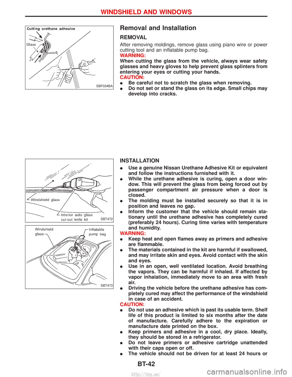
After removing moldings, remove glass using piano wire or power
cutting tool and an inflatable pump bag.
WARNING:
When cutting the glass from the vehicle, always wear safety
glasses and heavy gloves to help prevent glass splinters from
entering your eyes or cutting your hands.
CAUTION:
IBe careful not to scratch the glass when removing.
I Do not set or stand the glass on its edge. Small chips may
develop into cracks.
INSTALLATION
IUse a genuine Nissan Urethane Adhesive Kit or equivalent
and follow the instructions furnished with it.
I While the urethane adhesive is curing, open a door win-
dow. This will prevent the glass from being forced out by
passenger compartment air pressure when a door is
closed.
I The molding must be installed securely so that it is in
position and leaves no gap.
I Inform the customer that the vehicle should remain sta-
tionary until the urethane adhesive has completely cured
(preferably 24 hours). Curing time varies with temperature
and humidity.
WARNING:
I Keep heat and open flames away as primers and adhesive
are flammable.
I The materials contained in the kit are harmful if swallowed,
and may irritate skin and eyes. Avoid contact with the skin
and eyes.
I Use in an open, well ventilated location. Avoid breathing
the vapors. They can be harmful if inhaled. If affected by
vapor inhalation, immediately move to an area with fresh
air.
I Driving the vehicle before the urethane adhesive has com-
pletely cured may affect the performance of the windshield
in case of an accident.
CAUTION:
I Do not use an adhesive which is past its usable term. Shelf
life of this product is limited to six months after the date
of manufacture. Carefully adhere to the expiration or
manufacture date printed on the box.
I Keep primers and adhesive in a cool, dry place. Ideally,
they should be stored in a refrigerator.
I Do not leave primers or adhesive cartridge unattended
with their caps open or off.
I The vehicle should not be driven for at least 24 hours or
SBF034BA
SBT472
SBT473
WINDSHIELD AND WINDOWS
BT-42
http://vnx.su/
Page 1514 of 1833
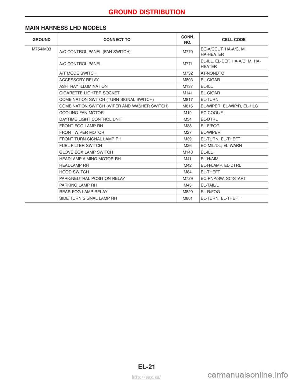
MAIN HARNESS LHD MODELS
GROUNDCONNECT TO CONN.
NO. CELL CODE
M754/M33 A/C CONTROL PANEL (FAN SWITCH) M770EC-A/CCUT, HA-A/C, M,
HA-HEATER
A/C CONTROL PANEL M771EL-ILL, EL-DEF, HA-A/C, M, HA-
HEATER
A/T MODE SWITCH M732 AT-NONDTC
ACCESSORY RELAY M803 EL-CIGAR
ASHTRAY ILLUMINATION M137 EL-ILL
CIGARETTE LIGHTER SOCKET M141 EL-CIGAR
COMBINATION SWITCH (TURN SIGNAL SWITCH) M817 EL-TURN
COMBINATION SWITCH (WIPER AND WASHER SWITCH) M816 EL-WIPER, EL-WIP/R, EL-HLC
COOLING FAN MOTOR M19 EC-COOL/F
DAYTIME LIGHT CONTROL UNIT M34 EL-DTRL
FRONT FOG LAMP RH M38 EL-F/FOG
FRONT WIPER MOTOR M27 EL-WIPER
FRONT TURN SIGNAL LAMP RH M39 EL-TURN, EL-THEFT
FUEL FILTER SWITCH M26 EC-MIL/DL, EL-WARN
GLOVE BOX LAMP SWITCH M143 EL-ILL
HEADLAMP AIMING MOTOR RH M41 EL-H/AIM
HEADLAMP RH M42 EL-H/LAMP, EL-DTRL
HOOD SWITCH M84 EL-THEFT
PARK/NEUTRAL POSITION RELAY M729 EC-PNP/SW, SC-START
PARKING LAMP RH M43 EL-TAIL/L
REAR FOG LAMP RELAY M820 EL-R/FOG
SIDE TURN SIGNAL LAMP RH M801 EL-TURN, EL-THEFT
GROUND DISTRIBUTION
EL-21
http://vnx.su/
Page 1515 of 1833
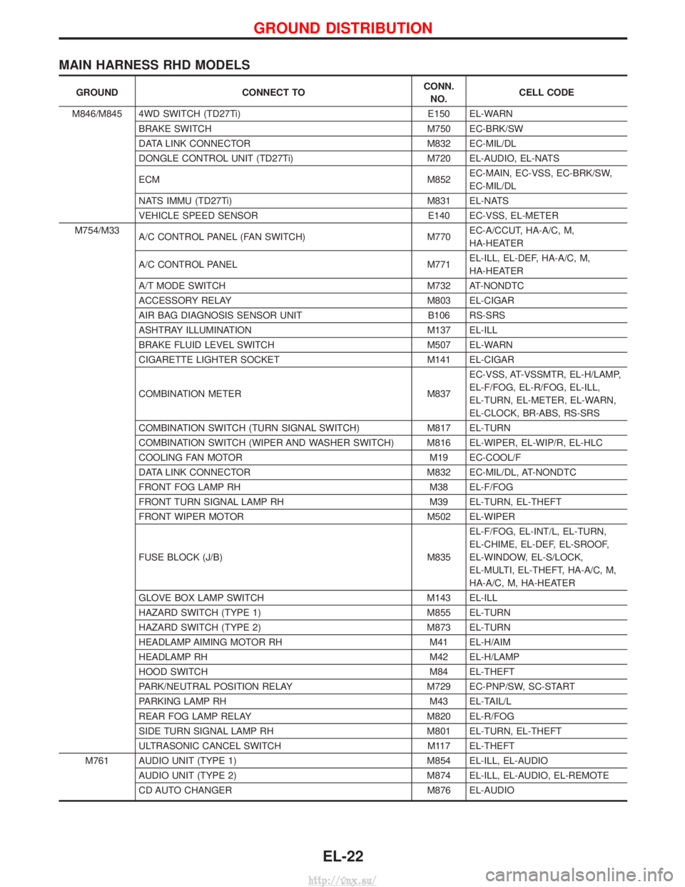
MAIN HARNESS RHD MODELS
GROUNDCONNECT TO CONN.
NO. CELL CODE
M846/M845 4WD SWITCH (TD27Ti) E150 EL-WARN
BRAKE SWITCH M750 EC-BRK/SW
DATA LINK CONNECTOR M832 EC-MIL/DL
DONGLE CONTROL UNIT (TD27Ti) M720 EL-AUDIO, EL-NATS
ECM M852EC-MAIN, EC-VSS, EC-BRK/SW,
EC-MIL/DL
NATS IMMU (TD27Ti) M831 EL-NATS
VEHICLE SPEED SENSOR E140 EC-VSS, EL-METER
M754/M33 A/C CONTROL PANEL (FAN SWITCH) M770EC-A/CCUT, HA-A/C, M,
HA-HEATER
A/C CONTROL PANEL M771EL-ILL, EL-DEF, HA-A/C, M,
HA-HEATER
A/T MODE SWITCH M732 AT-NONDTC
ACCESSORY RELAY M803 EL-CIGAR
AIR BAG DIAGNOSIS SENSOR UNIT B106 RS-SRS
ASHTRAY ILLUMINATION M137 EL-ILL
BRAKE FLUID LEVEL SWITCH M507 EL-WARN
CIGARETTE LIGHTER SOCKET M141 EL-CIGAR
COMBINATION METER M837EC-VSS, AT-VSSMTR, EL-H/LAMP,
EL-F/FOG, EL-R/FOG, EL-ILL,
EL-TURN, EL-METER, EL-WARN,
EL-CLOCK, BR-ABS, RS-SRS
COMBINATION SWITCH (TURN SIGNAL SWITCH) M817 EL-TURN
COMBINATION SWITCH (WIPER AND WASHER SWITCH) M816 EL-WIPER, EL-WIP/R, EL-HLC
COOLING FAN MOTOR M19 EC-COOL/F
DATA LINK CONNECTOR M832 EC-MIL/DL, AT-NONDTC
FRONT FOG LAMP RH M38 EL-F/FOG
FRONT TURN SIGNAL LAMP RH M39 EL-TURN, EL-THEFT
FRONT WIPER MOTOR M502 EL-WIPER
FUSE BLOCK (J/B) M835 EL-F/FOG, EL-INT/L, EL-TURN,
EL-CHIME, EL-DEF, EL-SROOF,
EL-WINDOW, EL-S/LOCK,
EL-MULTI, EL-THEFT, HA-A/C, M,
HA-A/C, M, HA-HEATER
GLOVE BOX LAMP SWITCH M143 EL-ILL
HAZARD SWITCH (TYPE 1) M855 EL-TURN
HAZARD SWITCH (TYPE 2) M873 EL-TURN
HEADLAMP AIMING MOTOR RH M41 EL-H/AIM
HEADLAMP RH M42 EL-H/LAMP
HOOD SWITCH M84 EL-THEFT
PARK/NEUTRAL POSITION RELAY M729 EC-PNP/SW, SC-START
PARKING LAMP RH M43 EL-TAIL/L
REAR FOG LAMP RELAY M820 EL-R/FOG
SIDE TURN SIGNAL LAMP RH M801 EL-TURN, EL-THEFT
ULTRASONIC CANCEL SWITCH M117 EL-THEFT
M761 AUDIO UNIT (TYPE 1) M854 EL-ILL, EL-AUDIO AUDIO UNIT (TYPE 2) M874 EL-ILL, EL-AUDIO, EL-REMOTE
CD AUTO CHANGER M876 EL-AUDIO
GROUND DISTRIBUTION
EL-22
http://vnx.su/