instrument panel NISSAN TERRANO 2004 Service Repair Manual
[x] Cancel search | Manufacturer: NISSAN, Model Year: 2004, Model line: TERRANO, Model: NISSAN TERRANO 2004Pages: 1833, PDF Size: 53.42 MB
Page 7 of 1833
insulation (either just before the harness connectors or for
the complete harness), for easy identification.
Precautions for NATS
NATS (Nissan Anti-Theft System)
NATS will immobilize the engine if someone tries to start it without
the registered key of NATS.
Both of the originally supplied ignition key IDs have been NATS
registered.
The NATS security indicator is located on the instrument panel. The
indicator blinks when the ignition switch is in ªOFFº or ªACCº posi-
tion. Therefore, NATS warns outsiders that the vehicle is equipped
with the anti-theft system.
IWhen NATS detects trouble, the malfunction indicator lamp
(MIL) blinks.
This blinking indicates that the anti-theft is not functioning, so
prompt service is required.
I If the malfunction indicator lamp comes on while the engine is
running, return the vehicle to the workshop before turning the
ignition switch ªOFFº.
Once the ignition switch is turned ªOFFº, the engine can not be
started.
I When servicing NATS (trouble diagnoses, system initialization
and additional registration of other NATS ignition key IDs) CON-
SULT-II hardware and CONSULT-II NATS software is neces-
sary.
Regarding the procedures of NATS initialization and NATS igni-
tion key ID registration, refer to CONSULT-II operation manual,
NATS.
Therefore, CONSULT-II NATS software (program card and
operation manual) must be kept strictly confidential to main-
tain the integrity of the anti-theft function.
I When servicing NATS (trouble diagnoses, system initialization
and additional registration of other NATS ignition key IDs), it
may be necessary to re-register original key identification.
Therefore, be sure to receive all keys from vehicle owner.
A maximum of five key IDs can be registered into NATS.
I When failing to start the engine first-time using the key of
NATS, starts as follows:
(1) Turn ignition key to ªOFFº.
(2) Wait approx. 5 seconds.
(3) Turn ignition key to ªSTARTº again while keeping the key
apart from any others on key-chain.
SGI916
PRECAUTIONS
Supplemental Restraint System (SRS) ªAIR
BAGº and ªSEAT BELT PRE-TENSIONERº
(Dual Air Bag System) (Cont'd)
GI-4
http://vnx.su/
Page 27 of 1833
Engine compartment
There are several reasons a vehicle or engine vibration could
cause an electrical complaint. Some of the things to check for are:
IConnectors not fully seated.
I Wiring harness not long enough and is being stressed due to
engine vibrations or rocking.
I Wires laying across brackets or moving components.
I Loose, dirty or corroded ground wires.
I Wires routed too close to hot components.
To inspect components under the hood, start by verifying the integ-
rity of ground connections. (Refer to GROUND INSPECTION
described later.) First check that the system is properly grounded.
Then check for loose connection by gently shakingthe wiring or
components as previously explained. Using the wiring diagrams
inspect the wiring for continuity.
Behind the instrument panel
An improperly routed or improperly clamped harness can become
pinched during accessory installation. Vehicle vibration can aggra-
vate a harness which is routed along a bracket or near a screw.
Under seating areas
An unclamped or loose harness can cause wiring to be pinched by
seat components (such as slide guides) during vehicle vibration. If
the wiring runs under seating areas, inspect wire routing for pos-
sible damage or pinching.
HEAT SENSITIVE
The owner's problem may occur during hot weather or after car has
sat for a short time. In such cases you will want to check for a heat
sensitive condition.
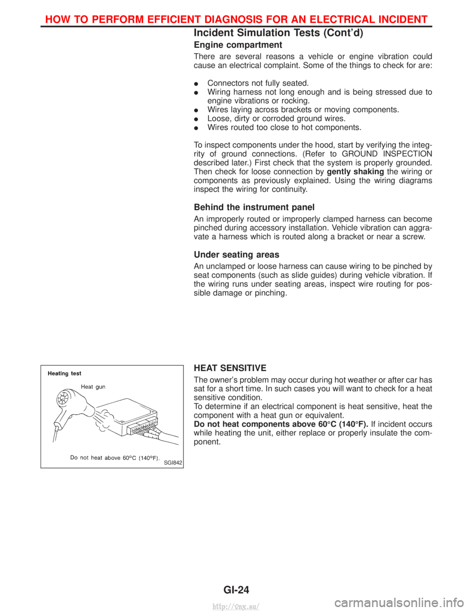
To determine if an electrical component is heat sensitive, heat the
component with a heat gun or equivalent.
Do not heat components above 60ÉC (140ÉF). If incident occurs
while heating the unit, either replace or properly insulate the com-
ponent.
SGI842
HOW TO PERFORM EFFICIENT DIAGNOSIS FOR AN ELECTRICAL INCIDENT
Incident Simulation Tests (Cont'd)
GI-24
http://vnx.su/
Page 44 of 1833
Shown below are Pre-delivery Inspection items required for the new vehicle. It is recommended that
necessary items other than those listed here be added, paying due regard to the conditions in each
country.
Perform applicable items on each model. Consult text of this section for specifications.
UNDER HOOD Ð engine off
lRadiator coolant level and coolant hose connections for leaks
l Battery fluid level, specific gravity and conditions of battery terminals
l Drive belts tension
l Fuel filter for water or dust, and fuel lines and connections for leaks
l Engine oil level and oil leaks
l Brake and clutch reservoirs fluid level and fluid lines for leaks
l Windshield and rear window washer and headlamp cleaner reservoir fluid level
l Power steering reservoir fluid level and hose connections for leaks
ON INSIDE AND OUTSIDE
lRemove front spring/strut spacer (if applicable)
l Operation of all instruments, gauges, lights and accessories
l Operation of horn(s), wiper and washer
l Steering lock for operation
l Check air conditioner for gas leaks
l Front and rear seats, and seat belts for operation
l All moldings, trims and fittings for fit and alignment
l All windows for operation and alignment
l Hood, tailgate, door panels for fit and alignment
l Latches, keys and locks for operation
l Weatherstrips for adhesion and fit
l Headlamp aiming
l Tighten wheel nuts (Inc. inner nuts if applicable)
l Tire pressure (Inc. spare tire)
l Check front wheels for toe-in
l Install clock/voltmeter/room lamp fuse (if applicable)
l Install deodorizing filter to air conditioner (if applicable)
l Remove wiper blade protectors (if applicable)
UNDER BODY
lManual transmission/transaxle, transfer and differential gear oil level
l Brake and fuel lines and oil/fluid reservoirs for leaks
l Tighten bolts and nuts of steering linkage and gear box, suspension, propeller shafts and drive shafts
l Tighten rear body bolts and nuts (Models with wooden bed only)
ROAD TEST
lClutch operation
l Parking brake operation
l Service brake operation
l Automatic transmission/transaxle shift timing and kickdown (if applicable)
l Steering control and returnability
l Engine performance
l Squeaks and rattles
ENGINE OPERATING AND HOT
lAdjust idle speed
l Automatic transmission/transaxle fluid level (if applicable)
l Engine idling and stop knob operation
FINAL INSPECTION
lInstall necessary parts (outside mirror, wheel covers, seat belts, mat, carpet or mud flaps)
l Inspect for interior and exterior metal and paint damage
l Check for spare tire, jack, tools (wheel check) and literature
l Wash, clean interior and exterior
PRE-DELIVERY INSPECTION ITEMS
MA-3
http://vnx.su/
Page 294 of 1833
System Chart
Input (Sensor)ECM FunctionOutput (Actuator)
I Electronic control fuel injection pump
I Crankshaft position sensor (TDC)
I Engine coolant temperature sensor
I Accelerator position sensor
I Accelerator position switch
I Accelerator switch (F/C)
I Park/Neutral position (PNP) switch
I Ignition switch
I Battery voltage
I Vehicle speed sensor
I Air conditioner switch
I Mass air flow sensor
I Stop lamp switch
I Heat up switch
I Charge air pressure sensor*1 Fuel injection control
Electronic control fuel injection pump
Fuel injection timing control Electronic control fuel injection pump
Fuel cut control Electronic control fuel injection pump
Glow control system Glow relay & glow lamp
On board diagnostic system MI (On the instrument panel)
EGR volume control EGR volume control valve
Cooling fan control Cooling fan relay
Air conditioning cut control Air conditioner relay
Variable nozzle turbocharger control Variable nozzle turbocharger control sole- noid valve
Swirl control valve control Swirl control valve control solenoid valve
Intake air control valve control Intake air control valve control solenoid
valve
*1: This sensor is not used to control the engine system under normal conditions.
ENGINE AND EMISSION CONTROL OVERALL SYSTEMZD30DDTi
EC-19
http://vnx.su/
Page 309 of 1833
IIf the battery is disconnected, the emission-related diagnostic information will be lost after approx.
24 hours.
I Erasing the emission-related diagnostic information using CONSULT-II is easier and quicker than
switching the diagnostic test mode using the data link connector.
NATS (Nissan Anti-Theft System)
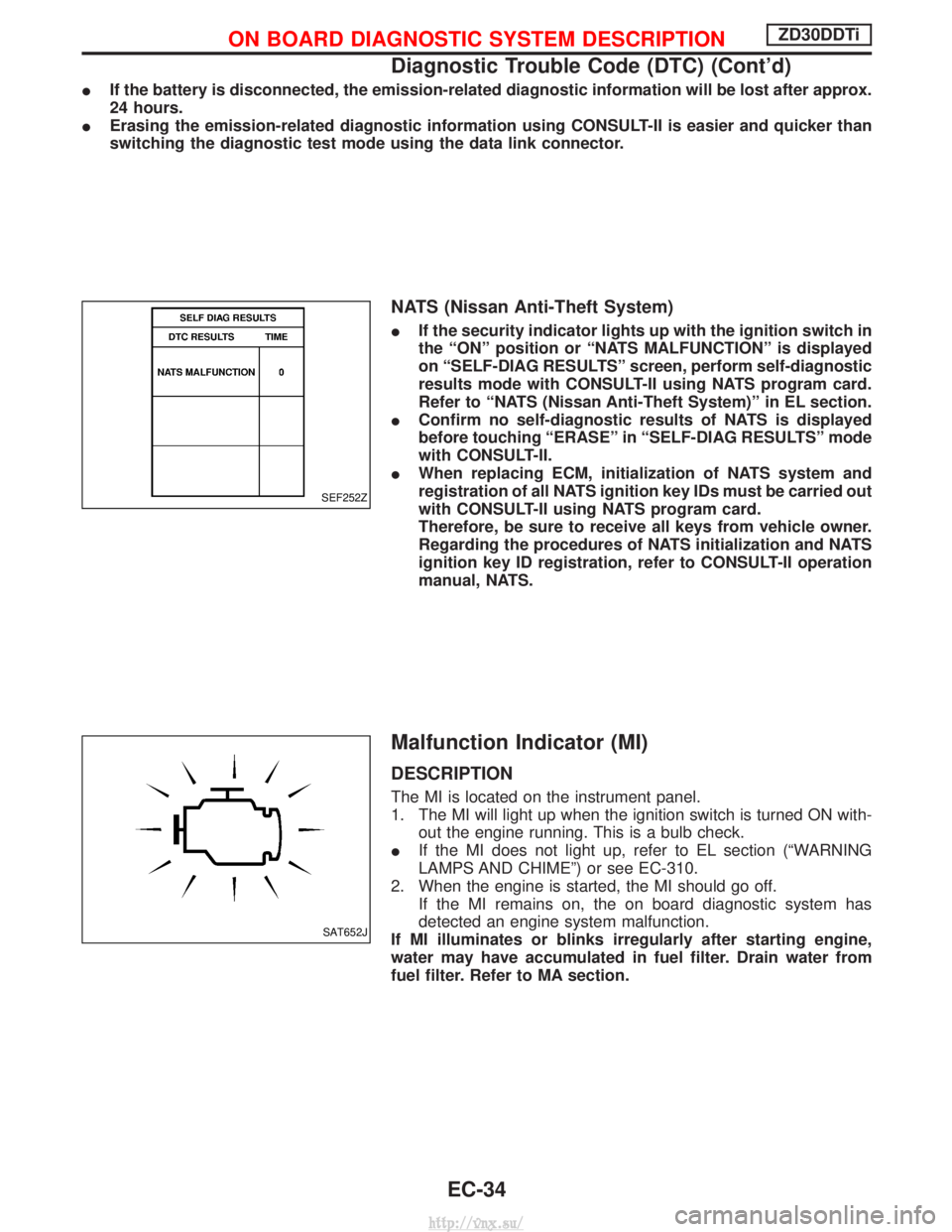
IIf the security indicator lights up with the ignition switch in
the ªONº position or ªNATS MALFUNCTIONº is displayed
on ªSELF-DIAG RESULTSº screen, perform self-diagnostic
results mode with CONSULT-II using NATS program card.
Refer to ªNATS (Nissan Anti-Theft System)º in EL section.
I Confirm no self-diagnostic results of NATS is displayed
before touching ªERASEº in ªSELF-DIAG RESULTSº mode
with CONSULT-II.
I When replacing ECM, initialization of NATS system and
registration of all NATS ignition key IDs must be carried out
with CONSULT-II using NATS program card.
Therefore, be sure to receive all keys from vehicle owner.
Regarding the procedures of NATS initialization and NATS
ignition key ID registration, refer to CONSULT-II operation
manual, NATS.
Malfunction Indicator (MI)
DESCRIPTION
The MI is located on the instrument panel.
1. The MI will light up when the ignition switch is turned ON with-
out the engine running. This is a bulb check.
I If the MI does not light up, refer to EL section (ªWARNING
LAMPS AND CHIMEº) or see EC-310.
2. When the engine is started, the MI should go off. If the MI remains on, the on board diagnostic system has
detected an engine system malfunction.
If MI illuminates or blinks irregularly after starting engine,
water may have accumulated in fuel filter. Drain water from
fuel filter. Refer to MA section.
SEF252Z
SAT652J
ON BOARD DIAGNOSTIC SYSTEM DESCRIPTIONZD30DDTi
Diagnostic Trouble Code (DTC) (Cont'd)
EC-34
http://vnx.su/
Page 312 of 1833
Diagnostic test mode I Ð Bulb check
In this mode, the MI on the instrument panel should stay ON. If it remains OFF, check the bulb. Refer to EL
section, ªWARNING LAMPS AND CHIMEº or see EC-310.
Diagnostic test mode I Ð Malfunction warning
MICondition
ON When the malfunction is detected or the ECM's CPU is malfunctioning.
OFF No malfunction.
Diagnostic test mode II Ð Self-diagnostic results
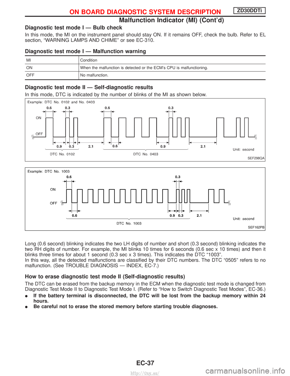
In this mode, DTC is indicated by the number of blinks of the MI as shown below.
Long (0.6 second) blinking indicates the two LH digits of number and short (0.3 second) blinking indicates the
two RH digits of number. For example, the MI blinks 10 times for 6 seconds (0.6 sec x 10 times) and then it
blinks three times for about 1 second (0.3 sec x 3 times). This indicates the DTC ª1003º.
In this way, all the detected malfunctions are classified by their DTC numbers. The DTC ª0505º refers to no
malfunction. (See TROUBLE DIAGNOSIS Ð INDEX, EC-7.)
How to erase diagnostic test mode II (Self-diagnostic results)
The DTC can be erased from the backup memory in the ECM when the diagnostic test mode is changed from
Diagnostic Test Mode II to Diagnostic Test Mode I. (Refer to ªHow to Switch Diagnostic Test Modesº, EC-36.)
I If the battery terminal is disconnected, the DTC will be lost from the backup memory within 24
hours.
I Be careful not to erase the stored memory before starting trouble diagnoses.
SEF298QA
SEF162PB
ON BOARD DIAGNOSTIC SYSTEM DESCRIPTIONZD30DDTi
Malfunction Indicator (MI) (Cont'd)
EC-37
http://vnx.su/
Page 344 of 1833
ECM Terminals and Reference Value
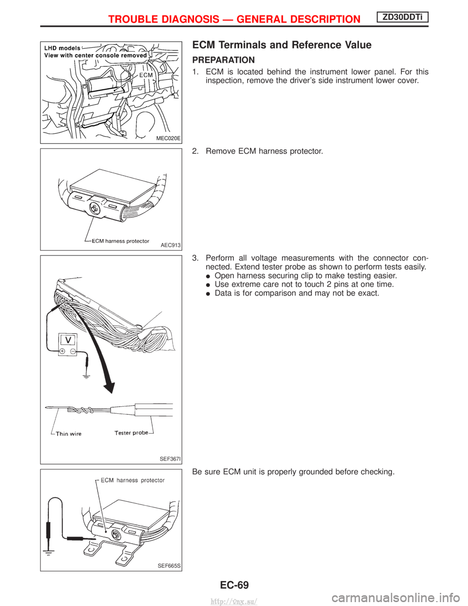
PREPARATION
1. ECM is located behind the instrument lower panel. For thisinspection, remove the driver's side instrument lower cover.
2. Remove ECM harness protector.
3. Perform all voltage measurements with the connector con- nected. Extend tester probe as shown to perform tests easily.
IOpen harness securing clip to make testing easier.
I Use extreme care not to touch 2 pins at one time.
I Data is for comparison and may not be exact.
Be sure ECM unit is properly grounded before checking.
MEC020E
AEC913
SEF367I
SEF665S
TROUBLE DIAGNOSIS Ð GENERAL DESCRIPTIONZD30DDTi
EC-69
http://vnx.su/
Page 540 of 1833
Component Description
The heat up switch is located on the lower side of the instrument
panel. This switch is used to speed up the heater's operation when
the engine is cold.
When the ECM received the heat up switch ªONº signal, the ECM
increases the engine idle speed to 1,100 to 1,200 rpm to warm up
engine quickly.
This system works when all conditions listed below are met.
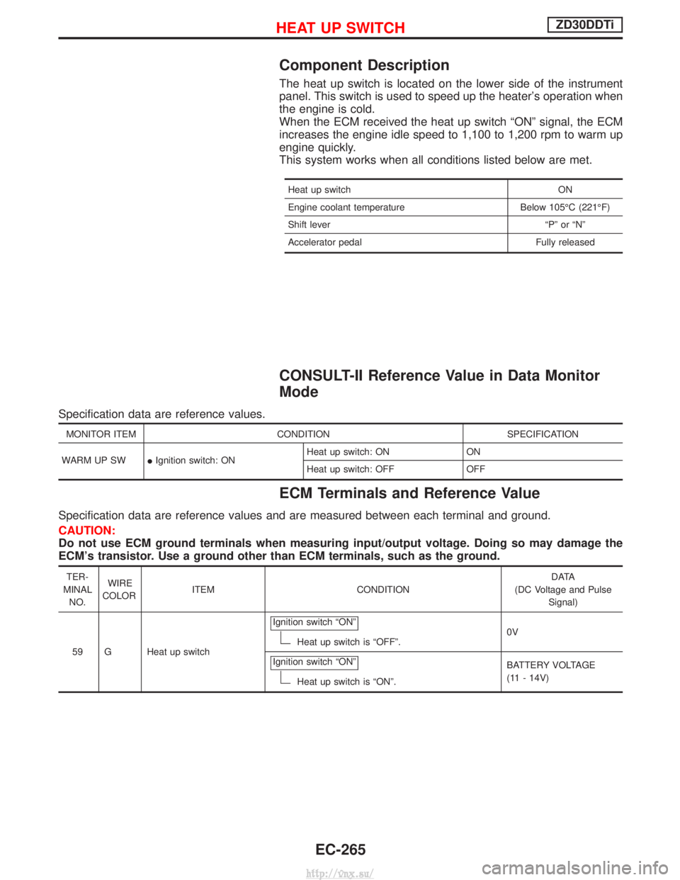
Heat up switchON
Engine coolant temperature Below 105ÉC (221ÉF)
Shift lever ªPº or ªNº
Accelerator pedal Fully released
CONSULT-II Reference Value in Data Monitor
Mode
Specification data are reference values.
MONITOR ITEMCONDITION SPECIFICATION
WARM UP SW IIgnition switch: ON Heat up switch: ON ON
Heat up switch: OFF OFF
ECM Terminals and Reference Value
Specification data are reference values and are measured between each terminal and ground.
CAUTION:
Do not use ECM ground terminals when measuring input/output voltage. Doing so may damage the
ECM's transistor. Use a ground other than ECM terminals, such as the ground.
TER-
MINAL NO. WIRE
COLOR ITEM CONDITION D ATA
(DC Voltage and Pulse Signal)
59 G Heat up switch Ignition switch ªONº
Heat up switch is ªOFFº.
0V
Ignition switch ªONº
Heat up switch is ªONº. BATTERY VOLTAGE
(11 - 14V)
HEAT UP SWITCHZD30DDTi
EC-265
http://vnx.su/
Page 590 of 1833
Precautions
SUPPLEMENTAL RESTRAINT SYSTEM (SRS) ªAIR BAGº AND ªSEAT BELT
PRE-TENSIONERº
The Supplemental Restraint System such as ªAIR BAGº and ªSEAT BELT PRE-TENSIONERº used along with
a seat belt, helps to reduce the risk or severity of injury to the driver and front passenger for certain types of
collision. The SRS composition which is available to NISSAN MODEL R20 is as follows (The composition
varies according to the destination and optional equipment.):
IFor a frontal collision
The Supplemental Restraint System consists of driver air bag module (located in the center of the steer-
ing wheel), front passenger air bag module (located on the instrument panel on passenger side), front seat
belt pre-tensioners, a diagnosis sensor unit, warning lamp, wiring harness and spiral cable.
I For a side collision
The Supplemental Restraint System consists of front side air bag module (located in the outer side of front
seat), side air bag (satellite) sensor, diagnosis sensor unit (one of components of air bags for a frontal
collision), wiring harness, warning lamp (one of components of air bags for a frontal collision).
WARNING:
I To avoid rendering the SRS inoperative, which could increase the risk of personal injury or death
in the event of a collision which would result in air bag inflation, all maintenance should be per-
formed by an authorized NISSAN dealer.
I Improper maintenance, including incorrect removal and installation of the SRS, can lead to per-
sonal injury caused by unintentional activation of the system.
I Do not use electrical test equipment on any circuit related to the SRS unless instructed to in this
Service Manual. Spiral cable and wiring harnesses covered with yellow insulation tape either just
before the harness connectors or for the complete harness are related to the SRS.
PRECAUTIONS
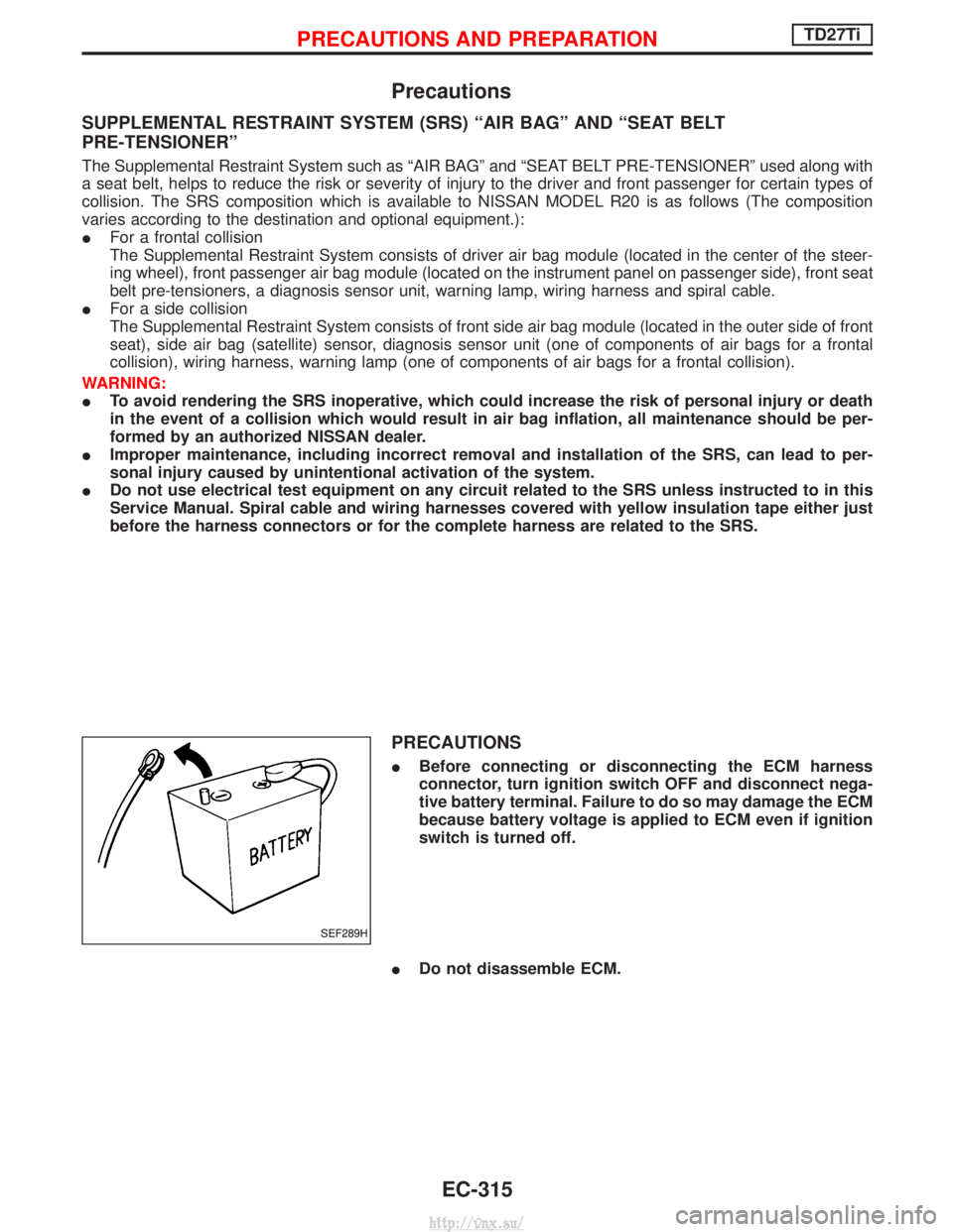
IBefore connecting or disconnecting the ECM harness
connector, turn ignition switch OFF and disconnect nega-
tive battery terminal. Failure to do so may damage the ECM
because battery voltage is applied to ECM even if ignition
switch is turned off.
I Do not disassemble ECM.
SEF289H
PRECAUTIONS AND PREPARATIONTD27Ti
EC-315
http://vnx.su/
Page 603 of 1833
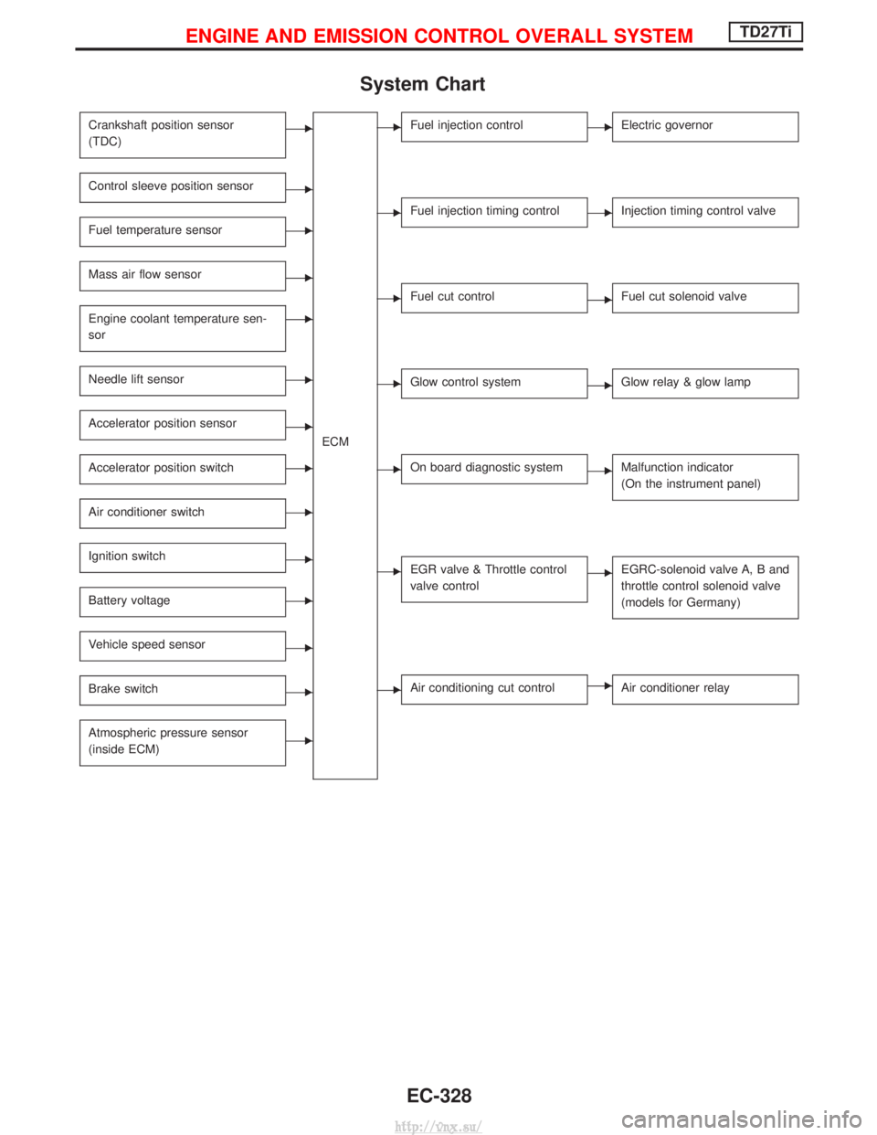
System Chart
Crankshaft position sensor
(TDC)E
ECM
Control sleeve position sensorE
Fuel temperature sensorE
Mass air flow sensorE
Engine coolant temperature sen-
sorE
Needle lift sensorE
Accelerator position sensorE
Accelerator position switchE
Air conditioner switchE
Ignition switchE
Battery voltageE
Vehicle speed sensorE
Brake switchE
Atmospheric pressure sensor
(inside ECM)E
EFuel injection controlEElectric governor
EFuel injection timing controlEInjection timing control valve
EFuel cut controlEFuel cut solenoid valve
EGlow control systemEGlow relay & glow lamp
EOn board diagnostic systemEMalfunction indicator
(On the instrument panel)
EEGR valve & Throttle control
valve controlEEGRC-solenoid valve A, B and
throttle control solenoid valve
(models for Germany)
EAir conditioning cut controlEAir conditioner relay
ENGINE AND EMISSION CONTROL OVERALL SYSTEMTD27Ti
EC-328
http://vnx.su/