trunk NISSAN TERRANO 2004 Service Repair Manual
[x] Cancel search | Manufacturer: NISSAN, Model Year: 2004, Model line: TERRANO, Model: NISSAN TERRANO 2004Pages: 1833, PDF Size: 53.42 MB
Page 18 of 1833
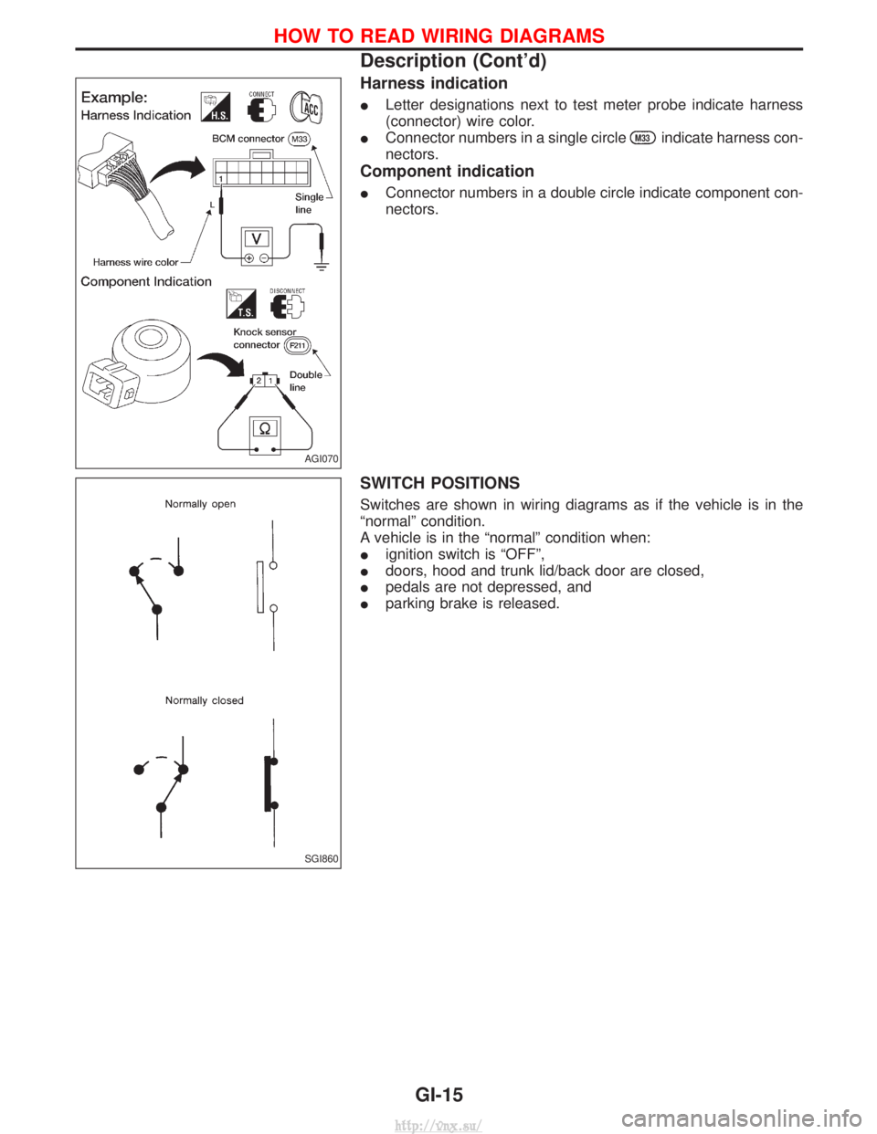
Harness indication
ILetter designations next to test meter probe indicate harness
(connector) wire color.
I Connector numbers in a single circle
M33indicate harness con-
nectors.
Component indication
I Connector numbers in a double circle indicate component con-
nectors.
SWITCH POSITIONS
Switches are shown in wiring diagrams as if the vehicle is in the
ªnormalº condition.
A vehicle is in the ªnormalº condition when:
Iignition switch is ªOFFº,
I doors, hood and trunk lid/back door are closed,
I pedals are not depressed, and
I parking brake is released.
AGI070
SGI860
HOW TO READ WIRING DIAGRAMS
Description (Cont'd)
GI-15
http://vnx.su/
Page 45 of 1833
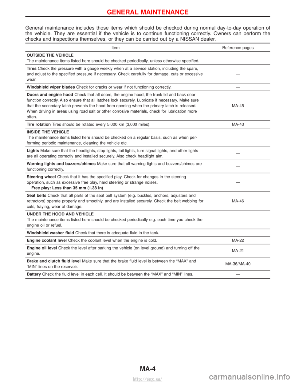
General maintenance includes those items which should be checked during normal day-to-day operation of
the vehicle. They are essential if the vehicle is to continue functioning correctly. Owners can perform the
checks and inspections themselves, or they can be carried out by a NISSAN dealer.
ItemReference pages
OUTSIDE THE VEHICLE
The maintenance items listed here should be checked periodically, unless otherwise specified.
Tires Check the pressure with a gauge weekly when at a service station, including the spare,
and adjust to the specified pressure if necessary. Check carefully for damage, cuts or excessive
wear. Ð
Windshield wiper blades Check for cracks or wear if not functioning correctly. Ð
Doors and engine hood Check that all doors, the engine hood, the trunk lid and back door
function correctly. Also ensure that all latches lock securely. Lubricate if necessary. Make sure
that the secondary latch prevents the hood from opening when the primary latch is released.
When driving in areas using road salt or other corrosive materials, check for lubrication more
often. MA-45
Tire rotation Tires should be rotated every 5,000 km (3,000 miles). MA-43
INSIDE THE VEHICLE
The maintenance items listed here should be checked on a regular basis, such as when per-
forming periodic maintenance, cleaning the vehicle etc.
Lights Make sure that the headlights, stop lights, tail lights, turn signal lights, and other lights
are all operating correctly and installed securely. Also check headlight aim. Ð
Warning lights and buzzers/chimes Make sure that all warning lights and buzzers/chimes are
functioning correctly. Ð
Steering wheel Check that it has the specified play. Check for changes in the steering
operation, such as excessive free play, hard steering or strange noises. Free play: Less than 35 mm (1.38 in) Ð
Seat belts Check that all parts of the seat belt system (e.g. buckles, anchors, adjusters and
retractors) operate properly and smoothly, and are installed securely. Check the belt webbing for
cuts, fraying, wear of damage. MA-46
UNDER THE HOOD AND VEHICLE
The maintenance items listed here should be checked periodically e.g. each time you check the
engine oil or refuel.
Windshield washer fluid Check that there is adequate fluid in the tank.
Engine coolant level Check the coolant level when the engine is cold. MA-22
Engine oil level Check the level after parking the vehicle (on level ground) and turning off the
engine. MA-21
Brake and clutch fluid level Make sure that the brake fluid level is between the ªMAXº and
ªMINº lines on the reservoir. MA-36/MA-40
Battery Check the fluid level in each cell. It should be between the ªMAXº and ªMINº lines. Ð
GENERAL MAINTENANCE
MA-4
http://vnx.su/
Page 88 of 1833
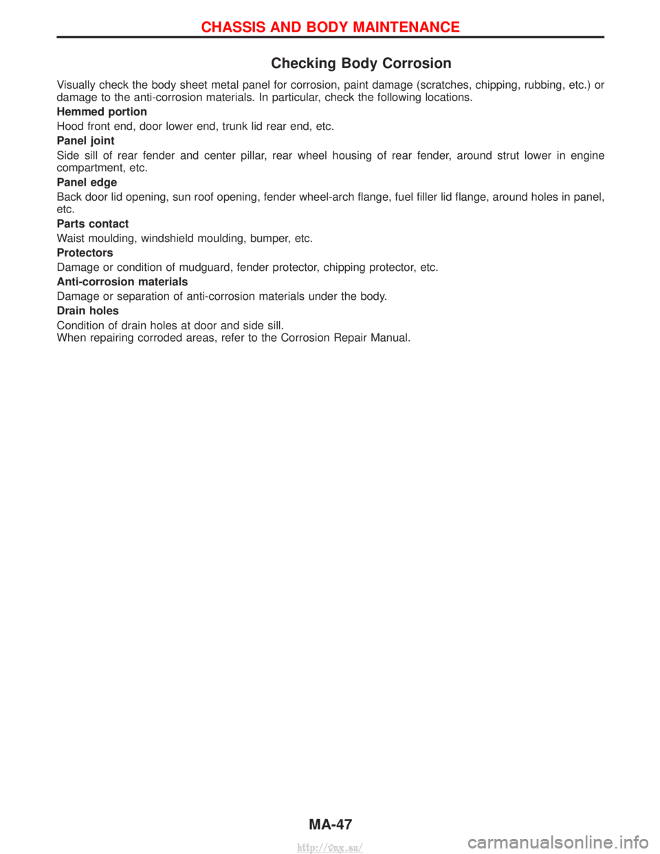
Checking Body Corrosion
Visually check the body sheet metal panel for corrosion, paint damage (scratches, chipping, rubbing, etc.) or
damage to the anti-corrosion materials. In particular, check the following locations.
Hemmed portion
Hood front end, door lower end, trunk lid rear end, etc.
Panel joint
Side sill of rear fender and center pillar, rear wheel housing of rear fender, around strut lower in engine
compartment, etc.
Panel edge
Back door lid opening, sun roof opening, fender wheel-arch flange, fuel filler lid flange, around holes in panel,
etc.
Parts contact
Waist moulding, windshield moulding, bumper, etc.
Protectors
Damage or condition of mudguard, fender protector, chipping protector, etc.
Anti-corrosion materials
Damage or separation of anti-corrosion materials under the body.
Drain holes
Condition of drain holes at door and side sill.
When repairing corroded areas, refer to the Corrosion Repair Manual.
CHASSIS AND BODY MAINTENANCE
MA-47
http://vnx.su/
Page 1712 of 1833
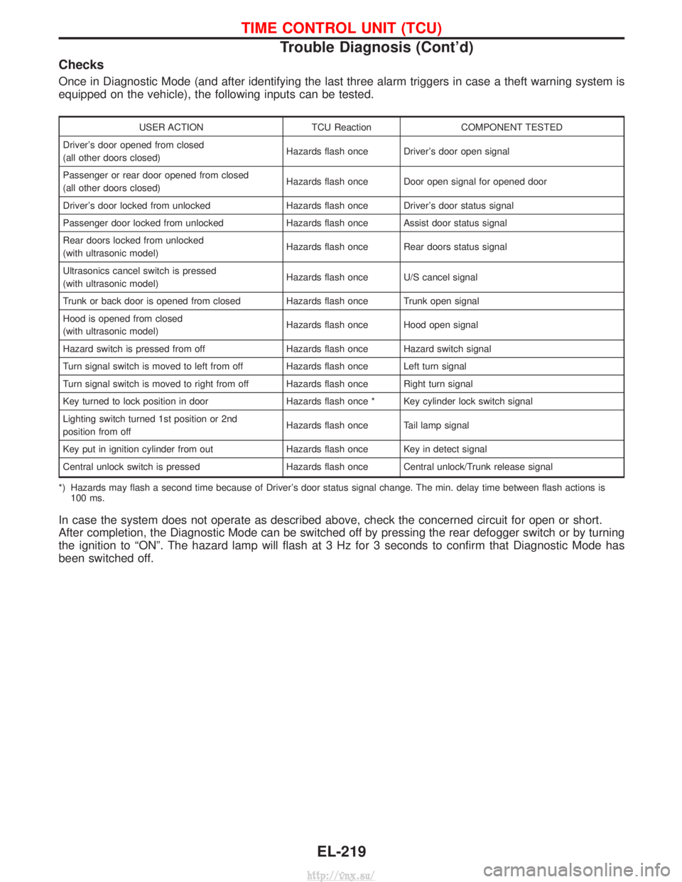
Checks
Once in Diagnostic Mode (and after identifying the last three alarm triggers in case a theft warning system is
equipped on the vehicle), the following inputs can be tested.
USER ACTIONTCU ReactionCOMPONENT TESTED
Driver's door opened from closed
(all other doors closed) Hazards flash once Driver's door open signal
Passenger or rear door opened from closed
(all other doors closed) Hazards flash once Door open signal for opened door
Driver's door locked from unlocked Hazards flash once Driver's door status signal
Passenger door locked from unlocked Hazards flash once Assist door status signal
Rear doors locked from unlocked
(with ultrasonic model) Hazards flash once Rear doors status signal
Ultrasonics cancel switch is pressed
(with ultrasonic model) Hazards flash once U/S cancel signal
Trunk or back door is opened from closed Hazards flash once Trunk open signal
Hood is opened from closed
(with ultrasonic model) Hazards flash once Hood open signal
Hazard switch is pressed from off Hazards flash once Hazard switch signal
Turn signal switch is moved to left from off Hazards flash once Left turn signal
Turn signal switch is moved to right from off Hazards flash once Right turn signal
Key turned to lock position in door Hazards flash once * Key cylinder lock switch signal
Lighting switch turned 1st position or 2nd
position from off Hazards flash once Tail lamp signal
Key put in ignition cylinder from out Hazards flash once Key in detect signal
Central unlock switch is pressed Hazards flash once Central unlock/Trunk release signal
*) Hazards may flash a second time because of Driver's door status signal change. The min. delay time between flash actions is 100 ms.
In case the system does not operate as described above, check the concerned circuit for open or short.
After completion, the Diagnostic Mode can be switched off by pressing the rear defogger switch or by turning
the ignition to ªONº. The hazard lamp will flash at 3 Hz for 3 seconds to confirm that Diagnostic Mode has
been switched off.
TIME CONTROL UNIT (TCU)
Trouble Diagnosis (Cont'd)
EL-219
http://vnx.su/
Page 1757 of 1833
Trouble Diagnoses
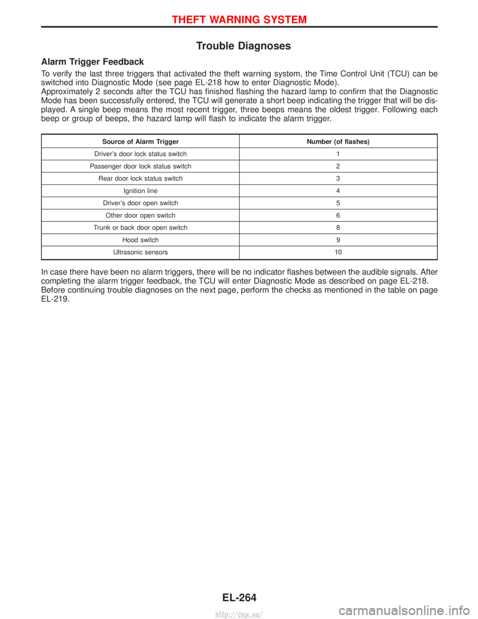
Alarm Trigger Feedback
To verify the last three triggers that activated the theft warning system, the Time Control Unit (TCU) can be
switched into Diagnostic Mode (see page EL-218 how to enter Diagnostic Mode).
Approximately 2 seconds after the TCU has finished flashing the hazard lamp to confirm that the Diagnostic
Mode has been successfully entered, the TCU will generate a short beep indicating the trigger that will be dis-
played. A single beep means the most recent trigger, three beeps means the oldest trigger. Following each
beep or group of beeps, the hazard lamp will flash to indicate the alarm trigger.
Source of Alarm TriggerNumber (of flashes)
Driver's door lock status switch 1
Passenger door lock status switch 2
Rear door lock status switch 3
Ignition line 4
Driver's door open switch 5
Other door open switch 6
Trunk or back door open switch 8
Hood switch 9
Ultrasonic sensors 10
In case there have been no alarm triggers, there will be no indicator flashes between the audible signals. After
completing the alarm trigger feedback, the TCU will enter Diagnostic Mode as described on page EL-218.
Before continuing trouble diagnoses on the next page, perform the checks as mentioned in the table on page
EL-219.
THEFT WARNING SYSTEM
EL-264
http://vnx.su/
Page 1758 of 1833
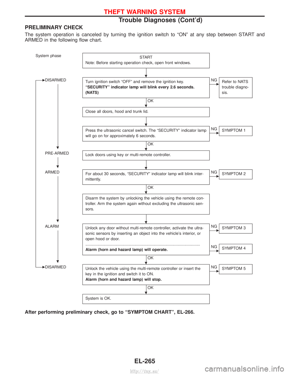
PRELIMINARY CHECK
The system operation is canceled by turning the ignition switch to ªONº at any step between START and
ARMED in the following flow chart.
System phaseSTART
Note: Before starting operation check, open front windows.
EDISARMED Turn ignition switch ªOFFº and remove the ignition key.
ªSECURITYº indicator lamp will blink every 2.6 seconds.
(NATS)
OK
ENGRefer to NATS
trouble diagno-
sis.
Close all doors, hood and trunk lid.
Press the ultrasonic cancel switch. The ªSECURITYº indicator lamp
will go on for approximately 6 seconds.
OK
ENGSYMPTOM 1
PRE-ARMED Lock doors using key or multi-remote controller.
ARMEDFor about 30 seconds, ªSECURITYº indicator lamp will blink inter-
mittently.
OK
ENGSYMPTOM 2
Disarm the system by unlocking the vehicle using the remote con-
troller. Arm the system again without excluding the ultrasonic sen-
sors.
ALARM Unlock any door without multi-remote controller, activate the ultra-
sonic sensors by inserting an object into the vehicle's interior, or
open hood or door.
........................................................................\
...............................
Alarm (horn and hazard lamp) will operate.
OK
ENGSYMPTOM 3
ENGSYMPTOM 4
EDISARMED Unlock the vehicle using the multi-remote controller or insert the
key in the ignition and switch it to ON.
Alarm (horn and hazard lamp) will stop.
OK
ENGSYMPTOM 5
System is OK.
After performing preliminary check, go to ªSYMPTOM CHARTº, EL-266.
H
H
H
HH
HH
H
HH
HH
H
THEFT WARNING SYSTEM
Trouble Diagnoses (Cont'd)
EL-265
http://vnx.su/
Page 1832 of 1833
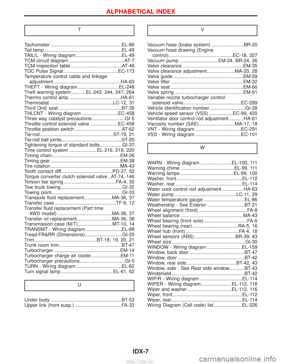
T
Tachometer .....................................................EL-86
Tail lamp ..........................................................EL-49
TAIL/L - Wiring diagram ..................................EL-49
TCM circuit diagram ..........................................AT-7
TCM inspection table ......................................AT-46
TDC Pulse Signal .........................................EC-173
Temperature control cable and linkageadjustment ..................................................HA-63
THEFT - Wiring diagram...............................EL-248
Theft warning system ...........EL-243, 244, 247, 264
Thermo control amp. ......................................HA-61
Thermostat................................................LC-12, 31
Third (3rd) seat ...............................................BT-39
THLCNT - Wiring diagram ...........................EC-458
Three way catalyst precautions.........................GI-5
Throttle control solenoid valve .....................EC-458
Throttle position switch ...................................AT-62
Tie-rod .......................................................ST-19, 21
Tie-rod ball joints.............................................ST-20
Tightening torque of standard bolts.................GI-37
Time control system .....................EL-216, 218, 220
Timing chain ...................................................EM-26
Timing gear ....................................................EM-38
Tire rotation ....................................................MA-43
Tooth contact diff. .....................................PD-27, 52
Torque converter clutch solenoid valve ..AT-74, 146
Torsion bar spring .......................................FA-4, 30
Tow truck towing ..............................................GI-32
Towing point.....................................................GI-33
Transaxle fluid replacement.....................MA-36, 37
Transfer case ..............................................TF-9, 12
Transfer fluid replacement (Part time 4WD model) .........................................MA-36, 37
Transfer oil replacement ..........................MA-36, 38
Transmission case (M/T)..........................MT-10, 14
TRANSMT - Wiring diagram ...........................EL-98
Tread-FR&RR (Dimensions)............................GI-25
Trim...............................................BT-18, 19, 20, 21
Trunk room trim...............................................BT-47
Turbocharger ..................................................EM-14
Turbocharger charge air cooler......................EM-11
Turbocharger precautions..................................GI-5
TURN - Wiring diagram ..................................EL-62
Turn signal lamp .......................................EL-61, 62
U
Under body .....................................................BT-53
Upper link (front susp.) ...................................FA-33 V
Vacuum hose (brake system) ........................BR-20
Vacuum hose drawing (Engine
control)................................................EC-18, 327
Vacuum pump .............................EM-24, BR-24, 26
Valve clearance..............................................EM-35
Valve clearance adjustment.....................MA-20, 28
Valve guide ....................................................EM-59
Valve lifter ......................................................EM-32
Valve seat ......................................................EM-60
Valve spring ...................................................EM-61
Variable nozzle turbocharger control solenoid valve ...........................................EC-289
Vehicle identification number...........................GI-28
Vehicle speed sensor (VSS) ..................EC-99, 420
Ventilator door control rod adjustment ...........HA-61
Viscosity number (SAE)...........................MA-17, 18
VNT - Wiring diagram ..................................EC-291
VSS - Wiring diagram ..................................EC-101
W
WARN - Wiring diagram........................EL-100, 111
Warning chime ........................................EL-99, 111
Warning lamps ........................................EL-99, 100
Washer, front .................................................EL-112
Washer, rear ..................................................EL-114
Water cock control rod adjustment ................HA-63
Water pump ..............................................LC-11, 29
Water temperature gauge ...............................EL-86
Weatherstrip - See Exterior ............................BT-21
Wheel alignment (front) ....................................FA-8
Wheel balance ...............................................MA-43
Wheel bearing (front axle) ................................FA-6
Wheel bearing (rear) ..................................RA-5, 16
Wheel hub (front) ........................................FA-4, 18
Wheel sensors (ABS)...............................BR-39, 43
Wheel size .......................................................GI-30
WINDOW - Wiring diagram ..........................EL-159
Window, back door .........................................BT-47
Window, door ..................................................BT-42
Window, rear side .....................................BT-42, 43
Window, side - See Rear side window ...........BT-43
Windshield.......................................................BT-42
WIP/R - Wiring diagram ................................EL-114
WIPER - Wiring diagram .......................EL-112, 118
Wiper and washer .................................EL-112, 116
Wiper, front ....................................................EL-112
Wiper, rear.....................................................EL-114
Wiring Diagram (Cell code) list .....................EL-326
ALPHABETICAL INDEX
IDX-7
http://vnx.su/