relay NISSAN TERRANO 2004 Service Repair Manual
[x] Cancel search | Manufacturer: NISSAN, Model Year: 2004, Model line: TERRANO, Model: NISSAN TERRANO 2004Pages: 1833, PDF Size: 53.42 MB
Page 15 of 1833
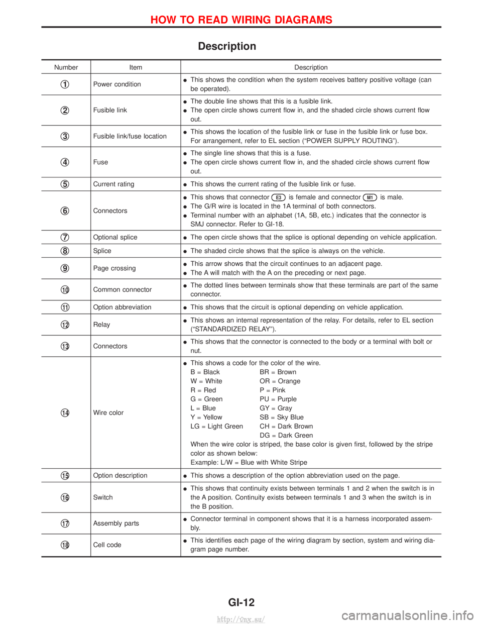
Description
NumberItem Description
q1Power conditionI
This shows the condition when the system receives battery positive voltage (can
be operated).
q2Fusible link I
The double line shows that this is a fusible link.
I The open circle shows current flow in, and the shaded circle shows current flow
out.
q3Fusible link/fuse location I
This shows the location of the fusible link or fuse in the fusible link or fuse box.
For arrangement, refer to EL section (ªPOWER SUPPLY ROUTINGº).
q4Fuse I
The single line shows that this is a fuse.
I The open circle shows current flow in, and the shaded circle shows current flow
out.
q5Current rating IThis shows the current rating of the fusible link or fuse.
q6Connectors I
This shows that connector
E3is female and connectorM1is male.
I The G/R wire is located in the 1A terminal of both connectors.
I Terminal number with an alphabet (1A, 5B, etc.) indicates that the connector is
SMJ connector. Refer to GI-18.
q7Optional splice IThe open circle shows that the splice is optional depending on vehicle application.
q8Splice IThe shaded circle shows that the splice is always on the vehicle.
q9Page crossing I
This arrow shows that the circuit continues to an adjacent page.
I The A will match with the A on the preceding or next page.
q10Common connector I
The dotted lines between terminals show that these terminals are part of the same
connector.
q11Option abbreviation IThis shows that the circuit is optional depending on vehicle application.
q12Relay I
This shows an internal representation of the relay. For details, refer to EL section
(ªSTANDARDIZED RELAYº).
q13Connectors I
This shows that the connector is connected to the body or a terminal with bolt or
nut.
q14Wire color I
This shows a code for the color of the wire.
B = Black BR = Brown
W = White OR = Orange
R = Red P = Pink
G = Green PU = Purple
L = Blue GY = Gray
Y = Yellow SB = Sky Blue
LG = Light Green CH = Dark Brown
DG = Dark Green
When the wire color is striped, the base color is given first, followed by the stripe
color as shown below:
Example: L/W = Blue with White Stripe
q15Option description IThis shows a description of the option abbreviation used on the page.
q16Switch I
This shows that continuity exists between terminals 1 and 2 when the switch is in
the A position. Continuity exists between terminals 1 and 3 when the switch is in
the B position.
q17Assembly parts I
Connector terminal in component shows that it is a harness incorporated assem-
bly.
q18Cell code I
This identifies each page of the wiring diagram by section, system and wiring dia-
gram page number.
HOW TO READ WIRING DIAGRAMS
GI-12
http://vnx.su/
Page 26 of 1833
Incident Simulation Tests
INTRODUCTION
Sometimes the symptom is not present when the vehicle is brought in for service. If possible, re-create the
conditions present at the time of the incident. Doing so may help avoid a No Trouble Found Diagnosis. The
following section illustrates ways to simulate the conditions/environment under which the owner experiences
an electrical incident.
The section is broken into the six following topics:
IVehicle vibration
I Heat sensitive
I Freezing
I Water intrusion
I Electrical load
I Cold or hot start up
Get a thorough description of the incident from the customer. It is important for simulating the conditions of
the problem.
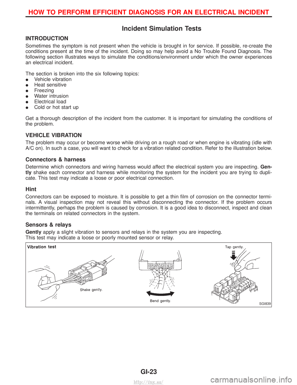
VEHICLE VIBRATION
The problem may occur or become worse while driving on a rough road or when engine is vibrating (idle with
A/C on). In such a case, you will want to check for a vibration related condition. Refer to the illustration below.
Connectors & harness
Determine which connectors and wiring harness would affect the electrical system you are inspecting. Gen-
tly shake each connector and harness while monitoring the system for the incident you are trying to dupli-
cate. This test may indicate a loose or poor electrical connection.
Hint
Connectors can be exposed to moisture. It is possible to get a thin film of corrosion on the connector termi-
nals. A visual inspection may not reveal this without disconnecting the connector. If the problem occurs
intermittently, perhaps the problem is caused by corrosion. It is a good idea to disconnect, inspect and clean
the terminals on related connectors in the system.
Sensors & relays
Gently apply a slight vibration to sensors and relays in the system you are inspecting.
This test may indicate a loose or poorly mounted sensor or relay.
SGI839
HOW TO PERFORM EFFICIENT DIAGNOSIS FOR AN ELECTRICAL INCIDENT
GI-23
http://vnx.su/
Page 280 of 1833
On Board Diagnosis Logic.......................................395
DTC Confirmation Procedure ..................................395
Wiring Diagram ........................................................396
Diagnostic Procedure ..............................................397
Component Inspection .............................................398
DTC P0215 FUEL CUT S/V 1 .....................................399
Component Description ...........................................399
On Board Diagnosis Logic.......................................399
DTC Confirmation Procedure ..................................399
Wiring Diagram ........................................................400
Diagnostic Procedure ..............................................401
Component Inspection .............................................402
DTC P0216 INJ TIMING CONT/V, DTC P1246 F/
INJ TIMG F/B ...............................................................403
Component Description ...........................................403
On Board Diagnosis Logic.......................................403
DTC P0216 Confirmation Procedure.......................403
DTC P1246 Confirmation Procedure.......................404
Wiring Diagram ........................................................405
Diagnostic Procedure ..............................................406
Component Inspection .............................................407
DTC P0335 CRANK POS SEN (TDC) ........................408
Component Description ...........................................408
On Board Diagnosis Logic.......................................408
DTC Confirmation Procedure ..................................408
Wiring Diagram ........................................................409
Diagnostic Procedure ..............................................410
Component Inspection ............................................. 411
DTC P0380 GLOW RELAY, DTC P0381 GLOW
LAMP ........................................................................\
...412
System Description ..................................................412
Component Description ...........................................413
On Board Diagnosis Logic.......................................413
DTC Confirmation Procedure ..................................413
Wiring Diagram ........................................................414
Diagnostic Procedure ..............................................416
System Operation Check.........................................418
Component Inspection .............................................419
DTC P0500 VEHICLE SPEED SEN ............................420
Component Description ...........................................420
On Board Diagnosis Logic.......................................420
Overall Function Check ...........................................420
Wiring Diagram ........................................................421
Diagnostic Procedure ..............................................422
DTC P0571 BRAKE SW ..............................................423
Component Description ...........................................423
On Board Diagnosis Logic.......................................423
DTC Confirmation Procedure ..................................423
Wiring Diagram ........................................................424
Diagnostic Procedure ..............................................425
Component Inspection .............................................426
DTC P0650 MI .............................................................427 Component Description ...........................................427
On Board Diagnosis Logic.......................................427
DTC Confirmation Procedure ..................................427
Wiring Diagram ........................................................428
Diagnostic Procedure ..............................................429
DTC P1107 ECM 10 ....................................................430
Description ...............................................................430
On Board Diagnosis Logic.......................................430
DTC Confirmation Procedure ..................................430
Diagnostic Procedure ..............................................431
DTC P1206 F/INJ F/B 2 ..............................................432
Component Description ...........................................432
On Board Diagnosis Logic.......................................432
DTC Confirmation Procedure ..................................433
Wiring Diagram ........................................................434
Diagnostic Procedure ..............................................435
Component Inspection .............................................436
DTC P1207 CONT SLEEV POS SEN .........................437
Component Description ...........................................437
On Board Diagnosis Logic.......................................437
DTC Confirmation Procedure ..................................437
Wiring Diagram ........................................................438
Diagnostic Procedure ..............................................439
Component Inspection .............................................440
DTC P1217 OVER HEAT ............................................441
Description ...............................................................441
On Board Diagnosis Logic.......................................441
Overall Function Check ...........................................442
Wiring Diagram ........................................................443
Diagnostic Procedure ..............................................444
Main 12 Causes of Overheating..............................448
Component Inspection .............................................449
DTC P1240 NEEDLE LIFT SEN, DTC P1242
NEEDLE LIFT SE (RPM) .............................................450
Component Description ...........................................450
On Board Diagnosis Logic.......................................450
DTC Confirmation Procedure ..................................450
Wiring Diagram ........................................................451
Diagnostic Procedure ..............................................452
Component Inspection .............................................453
DTC P1404 EGR SOL/V A, DTC P1405 EGR SOL/
V B/P1407 THROTTLE SOLENOID VALVE ...............454
System Description ..................................................454
Component Description ...........................................454
On Board Diagnosis Logic.......................................455
DTC Confirmation Procedure ..................................455
Wiring Diagram ........................................................456
Diagnostic Procedure ..............................................459
Component Inspection .............................................462
DTC P1530 AIR CONDITIONER RLY .........................463
Component Description ...........................................463
On Board Diagnosis Logic.......................................463
CONTENTS(Cont'd)
EC-5
http://vnx.su/
Page 294 of 1833
System Chart
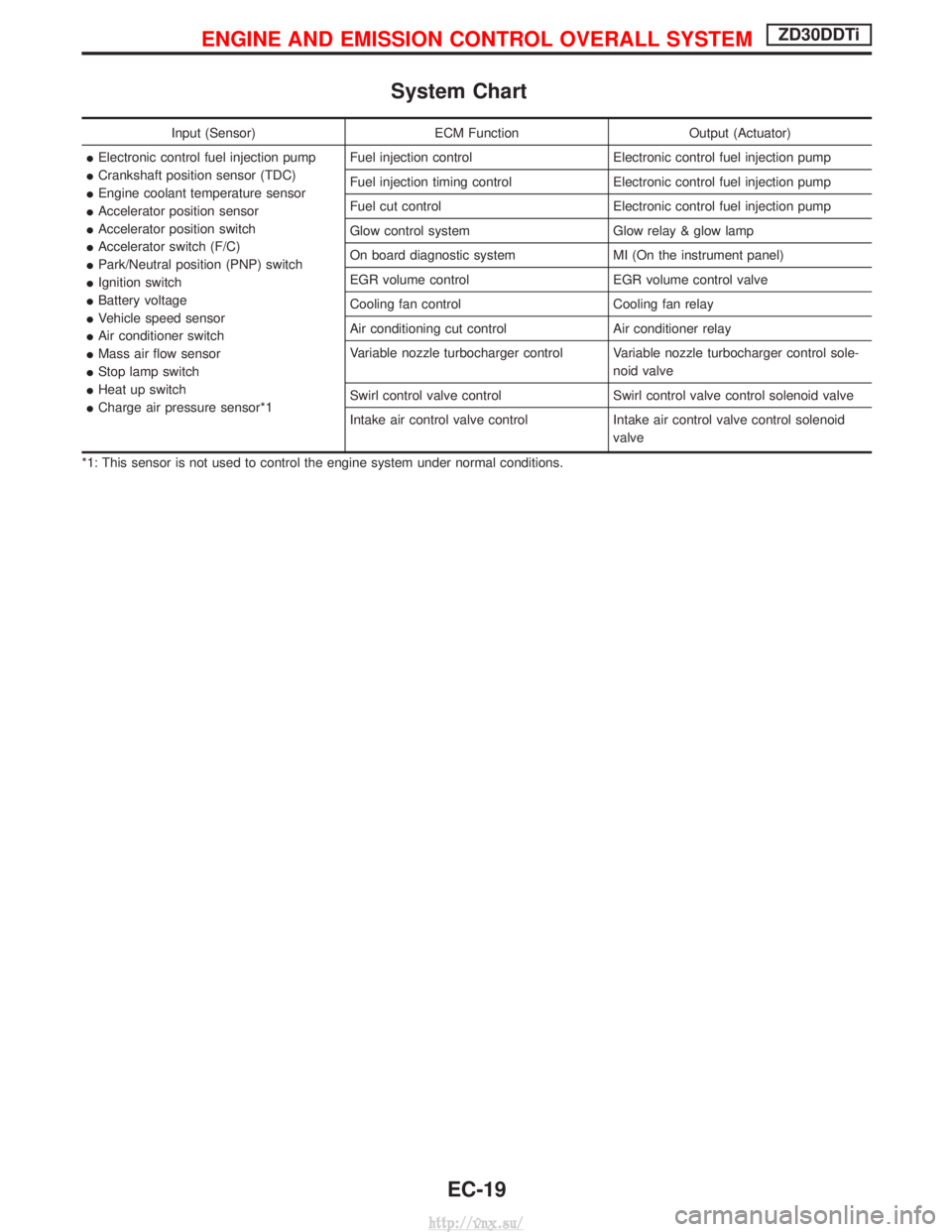
Input (Sensor)ECM FunctionOutput (Actuator)
I Electronic control fuel injection pump
I Crankshaft position sensor (TDC)
I Engine coolant temperature sensor
I Accelerator position sensor
I Accelerator position switch
I Accelerator switch (F/C)
I Park/Neutral position (PNP) switch
I Ignition switch
I Battery voltage
I Vehicle speed sensor
I Air conditioner switch
I Mass air flow sensor
I Stop lamp switch
I Heat up switch
I Charge air pressure sensor*1 Fuel injection control
Electronic control fuel injection pump
Fuel injection timing control Electronic control fuel injection pump
Fuel cut control Electronic control fuel injection pump
Glow control system Glow relay & glow lamp
On board diagnostic system MI (On the instrument panel)
EGR volume control EGR volume control valve
Cooling fan control Cooling fan relay
Air conditioning cut control Air conditioner relay
Variable nozzle turbocharger control Variable nozzle turbocharger control sole- noid valve
Swirl control valve control Swirl control valve control solenoid valve
Intake air control valve control Intake air control valve control solenoid
valve
*1: This sensor is not used to control the engine system under normal conditions.
ENGINE AND EMISSION CONTROL OVERALL SYSTEMZD30DDTi
EC-19
http://vnx.su/
Page 297 of 1833
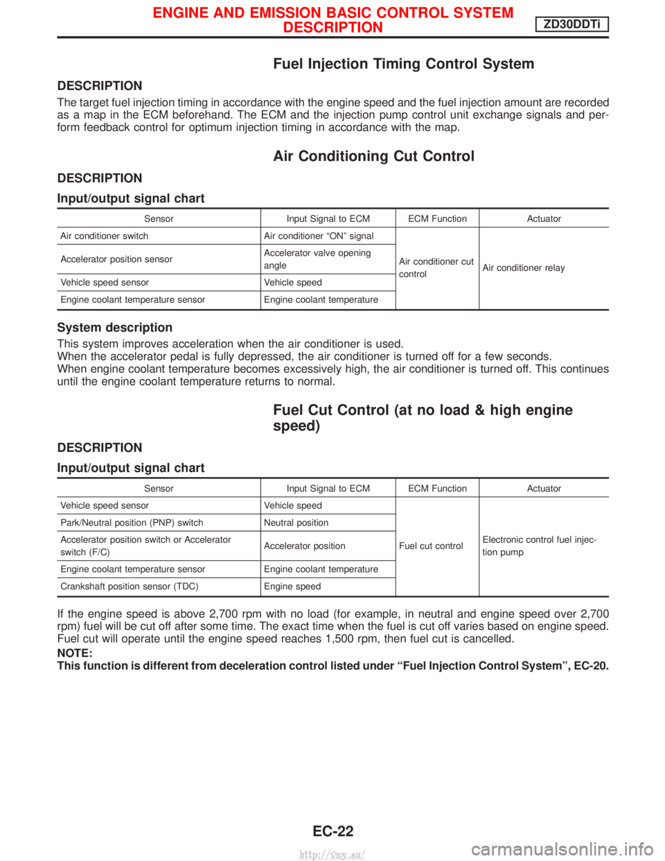
Fuel Injection Timing Control System
DESCRIPTION
The target fuel injection timing in accordance with the engine speed and the fuel injection amount are recorded
as a map in the ECM beforehand. The ECM and the injection pump control unit exchange signals and per-
form feedback control for optimum injection timing in accordance with the map.
Air Conditioning Cut Control
DESCRIPTION
Input/output signal chart
SensorInput Signal to ECM ECM Function Actuator
Air conditioner switch Air conditioner ªONº signal
Air conditioner cut
controlAir conditioner relay
Accelerator position sensor
Accelerator valve opening
angle
Vehicle speed sensor Vehicle speed
Engine coolant temperature sensor Engine coolant temperature
System description
This system improves acceleration when the air conditioner is used.
When the accelerator pedal is fully depressed, the air conditioner is turned off for a few seconds.
When engine coolant temperature becomes excessively high, the air conditioner is turned off. This continues
until the engine coolant temperature returns to normal.
Fuel Cut Control (at no load & high engine
speed)
DESCRIPTION
Input/output signal chart
SensorInput Signal to ECM ECM Function Actuator
Vehicle speed sensor Vehicle speed
Fuel cut controlElectronic control fuel injec-
tion pump
Park/Neutral position (PNP) switch
Neutral position
Accelerator position switch or Accelerator
switch (F/C) Accelerator position
Engine coolant temperature sensor Engine coolant temperature
Crankshaft position sensor (TDC) Engine speed
If the engine speed is above 2,700 rpm with no load (for example, in neutral and engine speed over 2,700
rpm) fuel will be cut off after some time. The exact time when the fuel is cut off varies based on engine speed.
Fuel cut will operate until the engine speed reaches 1,500 rpm, then fuel cut is cancelled.
NOTE:
This function is different from deceleration control listed under ªFuel Injection Control Systemº, EC-20.
ENGINE AND EMISSION BASIC CONTROL SYSTEM
DESCRIPTIONZD30DDTi
EC-22
http://vnx.su/
Page 315 of 1833
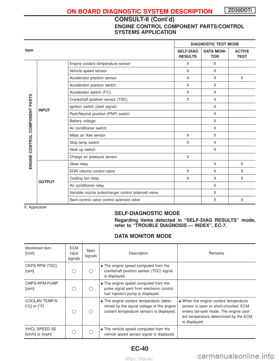
ENGINE CONTROL COMPONENT PARTS/CONTROL
SYSTEMS APPLICATION
ItemDIAGNOSTIC TEST MODE
SELF-DIAG RESULTS DATA MONI-
TOR ACTIVE
TEST
ENGINE CONTROL COMPONENT PARTS
INPUT Engine coolant temperature sensor X X
Vehicle speed sensor X X
Accelerator position sensor X X X
Accelerator position switch X X
Accelerator switch (F/C) X X
Crankshaft position sensor (TDC) X X
Ignition switch (start signal) X
Park/Neutral position (PNP) switch X
Battery voltage X
Air conditioner switch X
Mass air flow sensor X X
Stop lamp switch X X
Heat up switch X
Charge air pressure sensor X
OUTPUT Glow relay
XX
EGR volume control valve X X X
Cooling fan relay X X X
Air conditioner relay X
Variable nozzle turbocharger control solenoid valve X
Swirl control valve control solenoid valve X X
X: Applicable
SELF-DIAGNOSTIC MODE
Regarding items detected in ªSELF-DIAG RESULTSº mode,
refer to ªTROUBLE DIAGNOSIS Ð INDEXº, EC-7.
DATA MONITOR MODE
Monitored item
[Unit] ECM
input
signals Main
signals Description Remarks
CKPS×RPM (TDC)
[rpm] qqI
The engine speed computed from the
crankshaft position sensor (TDC) signal
is displayed.
CMPS×RPM×PUMP
[rpm] qqI
The engine speed computed from the
pulse signal sent from electronic control
fuel injection pump is displayed.
COOLAN TEMP/S
[ÉC] or [ÉF] qqI
The engine coolant temperature (deter-
mined by the signal voltage of the engine
coolant temperature sensor) is displayed. I
When the engine coolant temperature
sensor is open or short-circuited, ECM
enters fail-safe mode. The engine cool-
ant temperature determined by the ECM
is displayed.
VHCL SPEED SE
[km/h] or [mph] qqI
The vehicle speed computed from the
vehicle speed sensor signal is displayed.
ON BOARD DIAGNOSTIC SYSTEM DESCRIPTIONZD30DDTi
CONSULT-II (Cont'd)
EC-40
http://vnx.su/
Page 316 of 1833
![NISSAN TERRANO 2004 Service Repair Manual Monitored item
[Unit]ECM
input
signals Main
signals Description Remarks
FUEL TEMP SEN
[ÉC] or [ÉF] qqI
The fuel temperature (sent from elec-
tronic control fuel injection pump) is dis-
played.
ACCEL NISSAN TERRANO 2004 Service Repair Manual Monitored item
[Unit]ECM
input
signals Main
signals Description Remarks
FUEL TEMP SEN
[ÉC] or [ÉF] qqI
The fuel temperature (sent from elec-
tronic control fuel injection pump) is dis-
played.
ACCEL](/img/5/57394/w960_57394-315.png)
Monitored item
[Unit]ECM
input
signals Main
signals Description Remarks
FUEL TEMP SEN
[ÉC] or [ÉF] qqI
The fuel temperature (sent from elec-
tronic control fuel injection pump) is dis-
played.
ACCEL POS SEN [V] qqI
The accelerator position sensor signal
voltage is displayed.
FULL ACCEL SW
[ON/OFF] qqI
Indicates [ON/OFF] condition from the
accelerator position switch signal.
ACCEL SW (FC)
[OPEN/CLOSE] qqI
Indicates [OPEN/CLOSE] condition from
the accelerator switch (FC) signal.
OFF ACCEL SW
[ON/OFF] qqI
Indicates [ON/OFF] condition from the
accelerator position switch signal.
SPILL/V [ÉCA] qI
The control position of spill valve (sent
from electronic control fuel injection
pump) is displayed.
BATTERY VOLT [V] qqI
The power supply voltage of ECM is dis-
played.
P/N POSI SW
[ON/OFF] qqI
Indicates [ON/OFF] condition from the
park/neutral position switch signal.
START SIGNAL
[ON/OFF] qqI
Indicates [ON/OFF] condition from the
starter signal. I
After starting the engine, [OFF] is dis-
played regardless of the starter signal.
AIR COND SIG
[ON/OFF] qqI
Indicates [ON/OFF] condition of the air
conditioner switch as determined by the
air conditioner signal.
BRAKE SW [ON/OFF] qqI
Indicates [ON/OFF] condition from the
stop lamp switch signal.
IGN SW
[ON/OFF] qqI
Indicates [ON/OFF] condition from igni-
tion switch signal.
WARM UP SW
[ON/OFF] qI
Indicates [ON/OFF] condition from the
heat up switch signal.
MAS AIR/FL SE [V] qqI
The signal voltage of the mass air flow
sensor is displayed. I
When the engine is stopped, a certain
value is indicated.
DECELER F/CUT
[ON/OFF] qI
The [ON/OFF] condition from decelera-
tion fuel cut signal (sent from electronic
control fuel injection pump) is displayed.
INJ TIMG C/V [%] qI
The duty ratio of fuel injection timing
control valve (sent from electronic control
fuel injection pump) is displayed.
AIR COND RLY
[ON/OFF] qI
Indicates the control condition of the air
conditioner relay (determined by ECM
according to the input signals).
GLOW RLY [ON/OFF] qI
The glow relay control condition (deter-
mined by ECM according to the input
signal) is displayed.
COOLING FAN
[ON/OFF] qI
Indicates the control condition of the
cooling fans (determined by ECM
according to the input signal).
I ON ... Operates.
OFF ... Stopped.
ON BOARD DIAGNOSTIC SYSTEM DESCRIPTIONZD30DDTi
CONSULT-II (Cont'd)
EC-41
http://vnx.su/
Page 318 of 1833
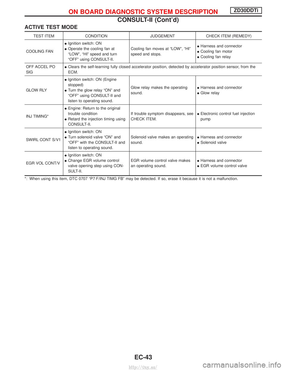
ACTIVE TEST MODE
TEST ITEMCONDITION JUDGEMENTCHECK ITEM (REMEDY)
COOLING FAN I
Ignition switch: ON
I Operate the cooling fan at
ªLOWº, ªHIº speed and turn
ªOFFº using CONSULT-II. Cooling fan moves at ªLOWº, ªHIº
speed and stops.
I
Harness and connector
I Cooling fan motor
I Cooling fan relay
OFF ACCEL PO
SIG I
Clears the self-learning fully closed accelerator position, detected by accelerator position sensor, from the
ECM.
GLOW RLY I
Ignition switch: ON (Engine
stopped)
I Turn the glow relay ªONº and
ªOFFº using CONSULT-II and
listen to operating sound. Glow relay makes the operating
sound.
I
Harness and connector
I Glow relay
INJ TIMING* I
Engine: Return to the original
trouble condition
I Retard the injection timing using
CONSULT-II. If trouble symptom disappears, see
CHECK ITEM.
I
Electronic control fuel injection
pump
SWIRL CONT S/V1 I
Ignition switch: ON
I Turn solenoid valve ªONº and
ªOFFº with the CONSULT-II and
listen to operating sound. Solenoid valve makes an operating
sound.
I
Harness and connector
I Solenoid valve
EGR VOL CONT/V I
Ignition switch: ON
I Change EGR volume control
valve opening step using CON-
SULT-II. EGR volume control valve makes
an operating sound.
I
Harness and connector
I EGR volume control valve
*: When using this item, DTC 0707 ªP7 ×F/INJ TIMG FBº may be detected. If so, erase it because it is not a malfunction.
ON BOARD DIAGNOSTIC SYSTEM DESCRIPTIONZD30DDTi
CONSULT-II (Cont'd)
EC-43
http://vnx.su/
Page 339 of 1833
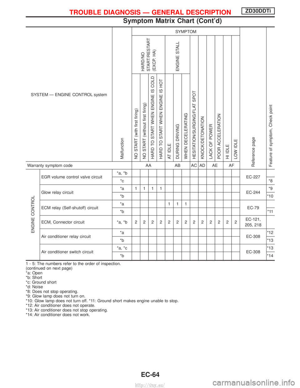
SYSTEM Ð ENGINE CONTROL system
Malfunction
SYMPTOM
Reference page
Feature of symptom, Check pointHARD/NO
START/RESTART
(EXCP. HA)
ENGINE STALL
HESITATION/SURGING/FLAT SPOT
KNOCK/DETONATION
LACK OF POWER
POOR ACCELERATION
HI IDLE
LOW IDLE NO START (with first firing)
NO START (without first firing)
HARD TO START WHEN ENGINE IS COLD
HARD TO START WHEN ENGINE IS HOT
AT IDLE
DURING DRIVING
WHEN DECELERATINGWarranty symptom code AAAB AC AD AE AF
ENGINE CONTROL
EGR volume control valve circuit *a, *b
EC-227
*c *8
Glow relay circuit *a 1111
EC-244*9
*b *10
ECM relay (Self-shutoff) circuit *a 111
EC-79
*b *11
ECM, Connector circuit *a, *b 2222222222222 EC-121,
205, 218
Air conditioner relay circuit *a
EC-308*12
*b *13
Air conditioner switch circuit *a, *c
EC-308*13
*b *14
1 - 5: The numbers refer to the order of inspection.
(continued on next page)
*a: Open
*b: Short
*c: Ground short
*d: Noise
*8: Does not stop operating.
*9: Glow lamp does not turn on.
*10: Glow lamp does not turn off. *11: Ground short makes engine unable to stop.
*12: Air conditioner does not operate.
*13: Air conditioner does not stop operating.
*14: Air conditioner does not work.
TROUBLE DIAGNOSIS Ð GENERAL DESCRIPTIONZD30DDTi
Symptom Matrix Chart (Cont'd)
EC-64
http://vnx.su/
Page 340 of 1833
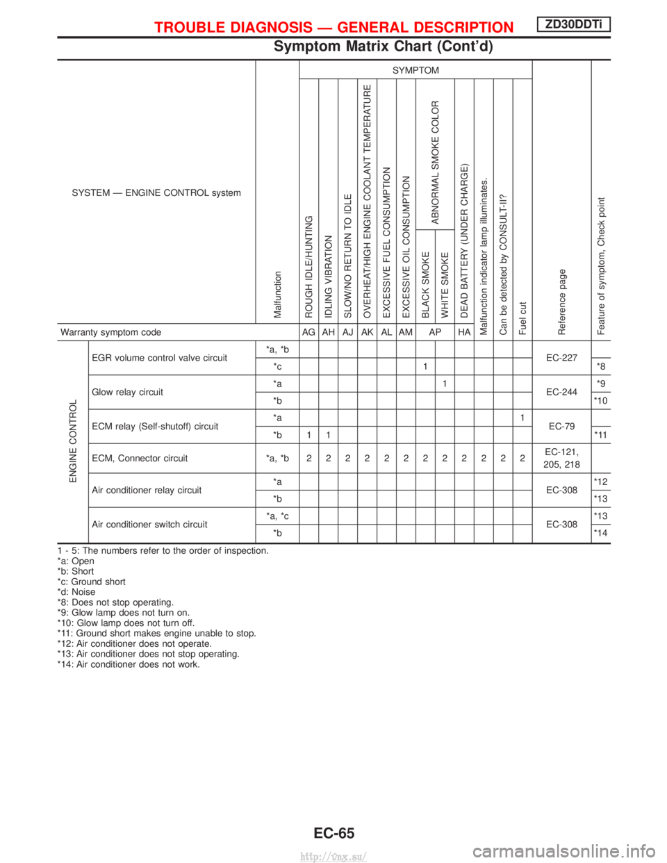
SYSTEM Ð ENGINE CONTROL system
Malfunction
SYMPTOM
Reference page
Feature of symptom, Check pointROUGH IDLE/HUNTING
IDLING VIBRATION
SLOW/NO RETURN TO IDLE
OVERHEAT/HIGH ENGINE COOLANT TEMPERATURE
EXCESSIVE FUEL CONSUMPTION
EXCESSIVE OIL CONSUMPTION
ABNORMAL SMOKE COLOR
DEAD BATTERY (UNDER CHARGE)
Malfunction indicator lamp illuminates.
Can be detected by CONSULT-II?
Fuel cut BLACK SMOKE
WHITE SMOKEWarranty symptom code
AG AH AJ AK AL AM AP HA
ENGINE CONTROL
EGR volume control valve circuit*a, *b
EC-227
*c 1 *8
Glow relay circuit *a 1
EC-244*9
*b *10
ECM relay (Self-shutoff) circuit *a 1
EC-79
*b 1 1 *11
ECM, Connector circuit *a, *b 222222222222 EC-121,
205, 218
Air conditioner relay circuit *a
EC-308*12
*b *13
Air conditioner switch circuit *a, *c
EC-308*13
*b *14
1 - 5: The numbers refer to the order of inspection.
*a: Open
*b: Short
*c: Ground short
*d: Noise
*8: Does not stop operating.
*9: Glow lamp does not turn on.
*10: Glow lamp does not turn off.
*11: Ground short makes engine unable to stop.
*12: Air conditioner does not operate.
*13: Air conditioner does not stop operating.
*14: Air conditioner does not work.
TROUBLE DIAGNOSIS Ð GENERAL DESCRIPTIONZD30DDTi
Symptom Matrix Chart (Cont'd)
EC-65
http://vnx.su/