run flat NISSAN TERRANO 2004 Service Repair Manual
[x] Cancel search | Manufacturer: NISSAN, Model Year: 2004, Model line: TERRANO, Model: NISSAN TERRANO 2004Pages: 1833, PDF Size: 53.42 MB
Page 122 of 1833
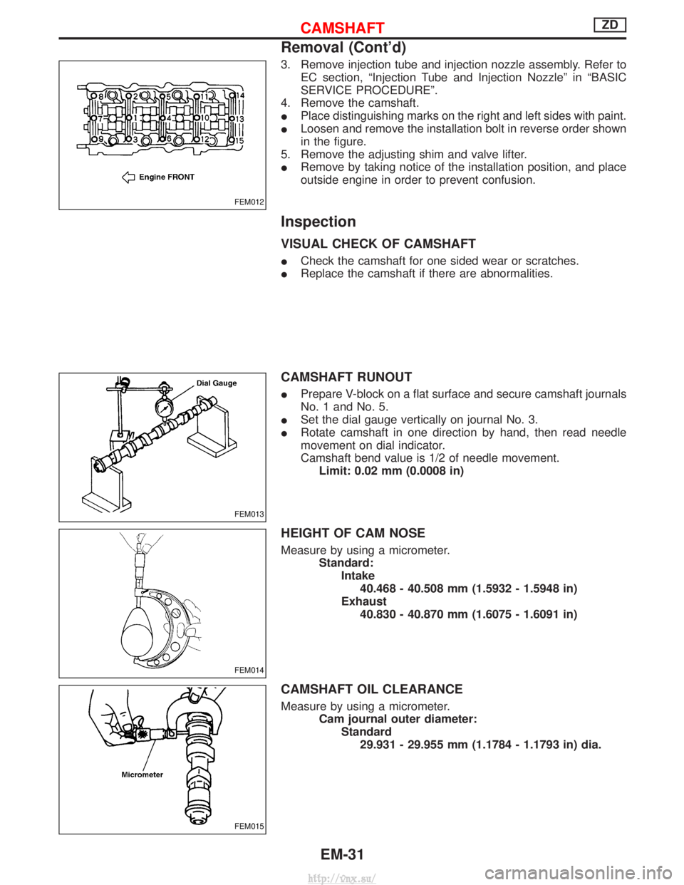
3. Remove injection tube and injection nozzle assembly. Refer toEC section, ªInjection Tube and Injection Nozzleº in ªBASIC
SERVICE PROCEDUREº.
4. Remove the camshaft.
I Place distinguishing marks on the right and left sides with paint.
I Loosen and remove the installation bolt in reverse order shown
in the figure.
5. Remove the adjusting shim and valve lifter.
I Remove by taking notice of the installation position, and place
outside engine in order to prevent confusion.
Inspection
VISUAL CHECK OF CAMSHAFT
ICheck the camshaft for one sided wear or scratches.
I Replace the camshaft if there are abnormalities.
CAMSHAFT RUNOUT
IPrepare V-block on a flat surface and secure camshaft journals
No. 1 and No. 5.
I Set the dial gauge vertically on journal No. 3.
I Rotate camshaft in one direction by hand, then read needle
movement on dial indicator.
Camshaft bend value is 1/2 of needle movement.
Limit: 0.02 mm (0.0008 in)
HEIGHT OF CAM NOSE
Measure by using a micrometer. Standard:Intake40.468 - 40.508 mm (1.5932 - 1.5948 in)
Exhaust 40.830 - 40.870 mm (1.6075 - 1.6091 in)
CAMSHAFT OIL CLEARANCE
Measure by using a micrometer. Cam journal outer diameter:Standard29.931 - 29.955 mm (1.1784 - 1.1793 in) dia.
FEM012
FEM013
FEM014
FEM015
CAMSHAFTZD
Removal (Cont'd)
EM-31
http://vnx.su/
Page 222 of 1833
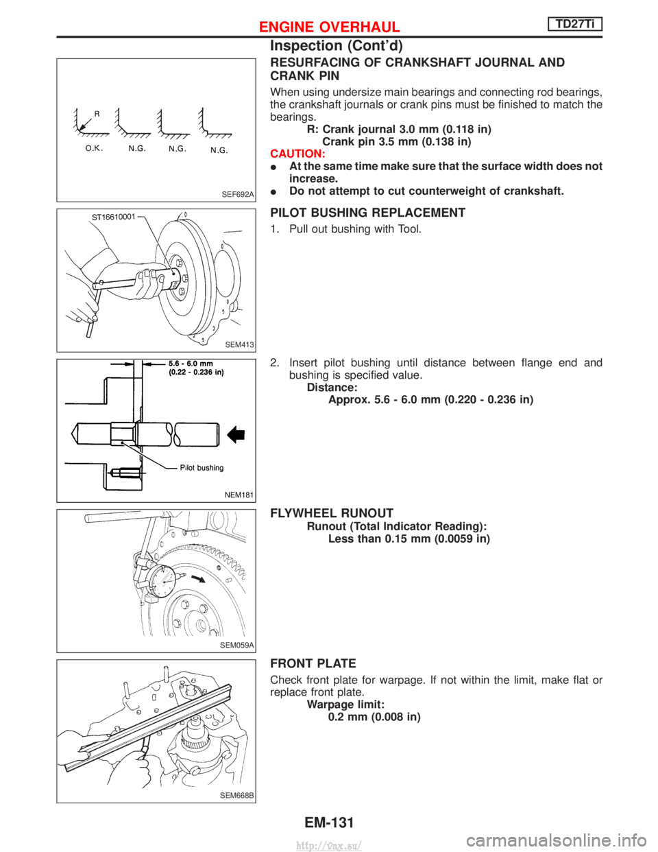
RESURFACING OF CRANKSHAFT JOURNAL AND
CRANK PIN
When using undersize main bearings and connecting rod bearings,
the crankshaft journals or crank pins must be finished to match the
bearings.R: Crank journal 3.0 mm (0.118 in)Crank pin 3.5 mm (0.138 in)
CAUTION:
I At the same time make sure that the surface width does not
increase.
I Do not attempt to cut counterweight of crankshaft.
PILOT BUSHING REPLACEMENT
1. Pull out bushing with Tool.
2. Insert pilot bushing until distance between flange end and
bushing is specified value.Distance: Approx. 5.6 - 6.0 mm (0.220 - 0.236 in)
FLYWHEEL RUNOUT
Runout (Total Indicator Reading):Less than 0.15 mm (0.0059 in)
FRONT PLATE
Check front plate for warpage. If not within the limit, make flat or
replace front plate. Warpage limit:0.2 mm (0.008 in)
SEF692A
SEM413
NEM181
SEM059A
SEM668B
ENGINE OVERHAULTD27Ti
Inspection (Cont'd)
EM-131
http://vnx.su/
Page 335 of 1833
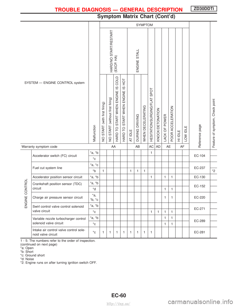
SYSTEM Ð ENGINE CONTROL system
Malfunction
SYMPTOM
Reference page
Feature of symptom, Check pointHARD/NO START/RESTART
(EXCP. HA)
ENGINE STALL
HESITATION/SURGING/FLAT SPOT
KNOCK/DETONATION
LACK OF POWER
POOR ACCELERATION
HI IDLE
LOW IDLE NO START (with first firing)
NO START (without first firing)
HARD TO START WHEN ENGINE IS COLD
HARD TO START WHEN ENGINE IS HOT
AT IDLE
DURING DRIVING
WHEN DECELERATINGWarranty symptom code AAAB AC AD AE AF
ENGINE CONTROL
Accelerator switch (FC) circuit *a, *b 1
EC-104
*c
Fuel cut system line *a, *c
EC-237
*b 1 1 1 1 *2
Accelerator position sensor circuit *a, *b 1 1 1 EC-130
Crankshaft position sensor (TDC)
circuit *a, *b
EC-152
*d 1 1
Charge air pressure sensor circuit *a,
*b, *c 1 1 EC-220
Swirl control valve control solenoid
valve circuit *a, *b
EC-271
*c 1111
Variable nozzle turbocharger control
solenoid valve circuit *a, *b 1 1
EC-289
*c 1 1
Intake air control valve control sole-
noid valve circuit *c 11111111
EC-281
1 - 5: The numbers refer to the order of inspection.
(continued on next page)
*a: Open
*b: Short
*c: Ground short
*d: Noise
*2: Engine runs on after turning ignition switch OFF.
TROUBLE DIAGNOSIS Ð GENERAL DESCRIPTIONZD30DDTi
Symptom Matrix Chart (Cont'd)
EC-60
http://vnx.su/
Page 639 of 1833
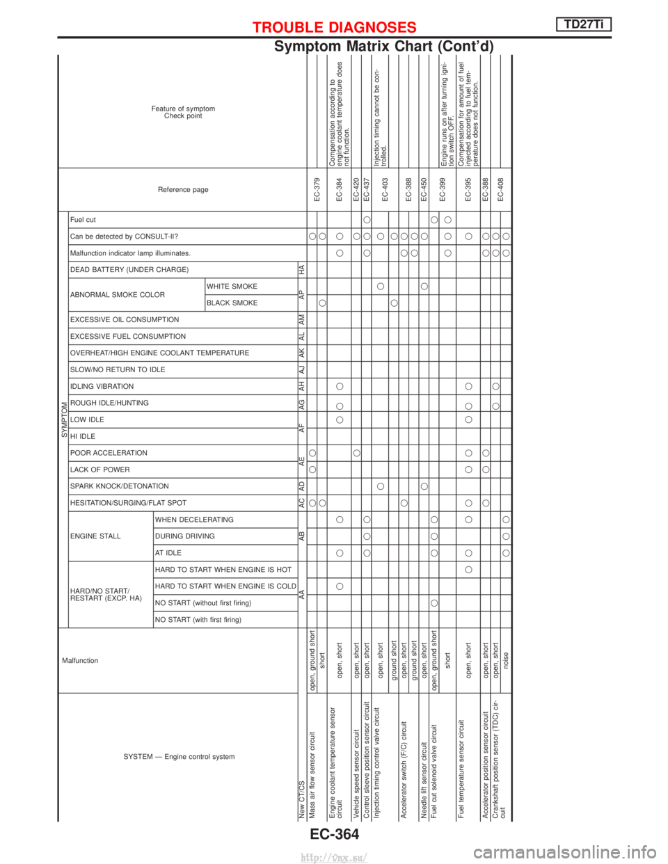
SYSTEM Ð Engine control system
Malfunction
SYMPTOM
Reference page
Feature of symptom
Check point
HARD/NO START/
RESTART (EXCP. HA) ENGINE STALL HESITATION/SURGING/FLAT SPOT SPARK KNOCK/DETONATION
LACK OF POWER
POOR ACCELERATION
HI IDLE
LOW IDLE
ROUGH IDLE/HUNTING
IDLING VIBRATION
SLOW/NO RETURN TO IDLE
OVERHEAT/HIGH ENGINE COOLANT TEMPERATURE
EXCESSIVE FUEL CONSUMPTION
EXCESSIVE OIL CONSUMPTION ABNORMAL SMOKE COLOR
DEAD BATTERY (UNDER CHARGE) Malfunction indicator lamp illuminates.
Can be detected by CONSULT-II?
Fuel cut NO START (with first firing)
NO START (without first firing)
HARD TO START WHEN ENGINE IS COLD
HARD TO START WHEN ENGINE IS HOT
AT IDLE
DURING DRIVING
WHEN DECELERATINGBLACK SMOKE
WHITE SMOKE
New CT/CS
AAAB AC AD AE AF AG AH AJ AK AL AM AP HA
Mass air flow sensor circuit open, ground short qqq q
EC-379
short qqq
Engine coolant temperature sensor
circuit open, short qqq qqq qq EC-384Compensation according to
engine coolant temperature does
not function.
Vehicle speed sensor circuit open, short qqEC-420
Control sleeve position sensor circuit open, short qqq qqqEC-437
Injection timing control valve circuit open, short qqq
EC-403Injection timing cannot be con-
trolled.
ground short qq
Accelerator switch (F/C) circuit open, short qqq
EC-388
ground short qq
Needle lift sensor circuit open, short qqqEC-450
Fuel cut solenoid valve circuit open, ground short q qqq q
EC-399
short qqqEngine runs on after turning igni-
tion switch OFF.
Fuel temperature sensor circuit open, shortqq qq qq qq q q EC-395Compensation for amount of fuel
injected according to fuel tem-
perature does not function.
Accelerator position sensor circuit open, short qqq qqEC-388
Crankshaft position sensor (TDC) cir-
cuit open, short
qq qq
EC-408
noise qqq qq
TROUBLE DIAGNOSESTD27Ti
Symptom Matrix Chart (Cont'd)
EC-364
http://vnx.su/
Page 1119 of 1833
Front Wheel Alignment
Before checking front wheel alignment, be sure to make a prelimi-
nary inspection.
PRELIMINARY INSPECTION
1. Check the tires for wear and proper inflation.
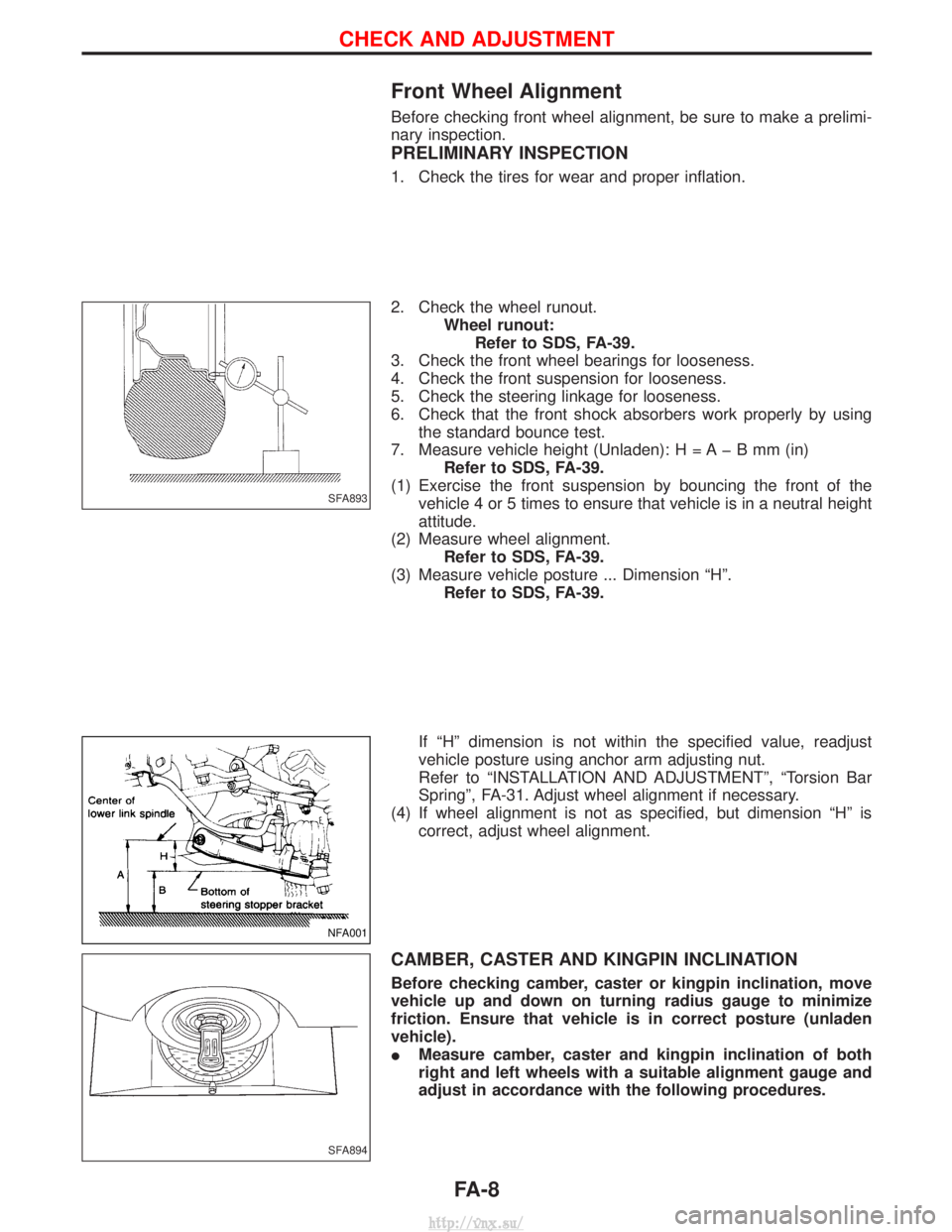
2. Check the wheel runout.Wheel runout:Refer to SDS, FA-39.
3. Check the front wheel bearings for looseness.
4. Check the front suspension for looseness.
5. Check the steering linkage for looseness.
6. Check that the front shock absorbers work properly by using the standard bounce test.
7. Measure vehicle height (Unladen): H = A þ B mm (in) Refer to SDS, FA-39.
(1) Exercise the front suspension by bouncing the front of the vehicle 4 or 5 times to ensure that vehicle is in a neutral height
attitude.
(2) Measure wheel alignment. Refer to SDS, FA-39.
(3) Measure vehicle posture ... Dimension ªHº. Refer to SDS, FA-39.
If ªHº dimension is not within the specified value, readjust
vehicle posture using anchor arm adjusting nut.
Refer to ªINSTALLATION AND ADJUSTMENTº, ªTorsion Bar
Springº, FA-31. Adjust wheel alignment if necessary.
(4) If wheel alignment is not as specified, but dimension ªHº is correct, adjust wheel alignment.
CAMBER, CASTER AND KINGPIN INCLINATION
Before checking camber, caster or kingpin inclination, move
vehicle up and down on turning radius gauge to minimize
friction. Ensure that vehicle is in correct posture (unladen
vehicle).
IMeasure camber, caster and kingpin inclination of both
right and left wheels with a suitable alignment gauge and
adjust in accordance with the following procedures.
SFA893
NFA001
SFA894
CHECK AND ADJUSTMENT
FA-8
http://vnx.su/