overheating NISSAN TERRANO 2004 Service Repair Manual
[x] Cancel search | Manufacturer: NISSAN, Model Year: 2004, Model line: TERRANO, Model: NISSAN TERRANO 2004Pages: 1833, PDF Size: 53.42 MB
Page 277 of 1833
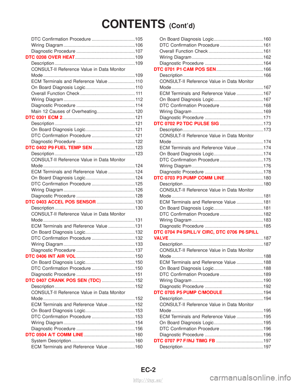
DTC Confirmation Procedure ..................................105
Wiring Diagram ........................................................106
Diagnostic Procedure ..............................................107
DTC 0208 OVER HEAT ...............................................109
Description ...............................................................109
CONSULT-II Reference Value in Data Monitor
Mode ........................................................................\
109
ECM Terminals and Reference Value ..................... 110
On Board Diagnosis Logic....................................... 110
Overall Function Check ........................................... 111
Wiring Diagram ........................................................ 112
Diagnostic Procedure .............................................. 114
Main 12 Causes of Overheating..............................120
DTC 0301 ECM 2.........................................................121 Description ...............................................................121
On Board Diagnosis Logic.......................................121
DTC Confirmation Procedure ..................................121
Diagnostic Procedure ..............................................122
DTC 0402 P9×FUEL TEMP SEN .................................123
Description ...............................................................123
CONSULT-II Reference Value in Data Monitor
Mode ........................................................................\
124
ECM Terminals and Reference Value .....................124
On Board Diagnosis Logic.......................................124
DTC Confirmation Procedure ..................................125
Wiring Diagram ........................................................126
Diagnostic Procedure ..............................................128
DTC 0403 ACCEL POS SENSOR ..............................130
Description ...............................................................130
CONSULT-II Reference Value in Data Monitor
Mode ........................................................................\
131
ECM Terminals and Reference Value .....................131
On Board Diagnosis Logic.......................................132
DTC Confirmation Procedure ..................................132
Wiring Diagram ........................................................133
Diagnostic Procedure ..............................................137
DTC 0406 INT AIR VOL ..............................................150
On Board Diagnosis Logic.......................................150
DTC Confirmation Procedure ..................................150
Diagnostic Procedure ..............................................151
DTC 0407 CRANK POS SEN (TDC) ..........................152
Description ...............................................................152
CONSULT-II Reference Value in Data Monitor
Mode ........................................................................\
152
ECM Terminals and Reference Value .....................152
On Board Diagnosis Logic.......................................153
DTC Confirmation Procedure ..................................153
Wiring Diagram ........................................................154
Diagnostic Procedure ..............................................156
DTC 0504 A/T COMM LINE ........................................160
System Description ..................................................160
ECM Terminals and Reference Value .....................160 On Board Diagnosis Logic.......................................160
DTC Confirmation Procedure ..................................161
Overall Function Check ...........................................161
Wiring Diagram ........................................................162
Diagnostic Procedure ..............................................164
DTC 0701 P1×CAM POS SEN .....................................166
Description ...............................................................166
CONSULT-II Reference Value in Data Monitor
Mode ........................................................................\
167
ECM Terminals and Reference Value .....................167
On Board Diagnosis Logic.......................................167
DTC Confirmation Procedure ..................................168
Wiring Diagram ........................................................169
Diagnostic Procedure ..............................................171
DTC 0702 P2×TDC PULSE SIG ..................................173
Description ...............................................................173
CONSULT-II Reference Value in Data Monitor
Mode ........................................................................\
174
ECM Terminals and Reference Value .....................174
On Board Diagnosis Logic.......................................174
DTC Confirmation Procedure ..................................175
Wiring Diagram ........................................................176
Diagnostic Procedure ..............................................178
DTC 0703 P3×PUMP COMM LINE ..............................180
Description ...............................................................180
CONSULT-II Reference Value in Data Monitor
Mode ........................................................................\
181
ECM Terminals and Reference Value .....................181
On Board Diagnosis Logic.......................................181
DTC Confirmation Procedure ..................................182
Wiring Diagram ........................................................183
Diagnostic Procedure ..............................................185
DTC 0704 P4×SPILL/V CIRC, DTC 0706 P6×SPILL
VA LV E ........................................................................\
..187
Description ...............................................................187
CONSULT-II Reference Value in Data Monitor
Mode ........................................................................\
188
ECM Terminals and Reference Value .....................188
On Board Diagnosis Logic.......................................188
DTC Confirmation Procedure ..................................189
Wiring Diagram ........................................................190
Diagnostic Procedure ..............................................192
DTC 0705 P5×PUMP C/MODULE ................................194
Description ...............................................................194
CONSULT-II Reference Value in Data Monitor
Mode ........................................................................\
195
ECM Terminals and Reference Value .....................195
On Board Diagnosis Logic.......................................195
DTC Confirmation Procedure ..................................196
Diagnostic Procedure ..............................................196
DTC 0707 P7×F/INJ TIMG FB .....................................197
Description ...............................................................197
CONTENTS(Cont'd)
EC-2
http://vnx.su/
Page 280 of 1833
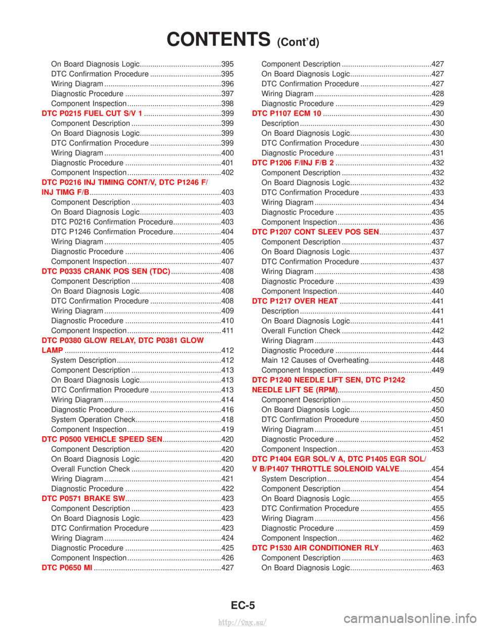
On Board Diagnosis Logic.......................................395
DTC Confirmation Procedure ..................................395
Wiring Diagram ........................................................396
Diagnostic Procedure ..............................................397
Component Inspection .............................................398
DTC P0215 FUEL CUT S/V 1 .....................................399
Component Description ...........................................399
On Board Diagnosis Logic.......................................399
DTC Confirmation Procedure ..................................399
Wiring Diagram ........................................................400
Diagnostic Procedure ..............................................401
Component Inspection .............................................402
DTC P0216 INJ TIMING CONT/V, DTC P1246 F/
INJ TIMG F/B ...............................................................403
Component Description ...........................................403
On Board Diagnosis Logic.......................................403
DTC P0216 Confirmation Procedure.......................403
DTC P1246 Confirmation Procedure.......................404
Wiring Diagram ........................................................405
Diagnostic Procedure ..............................................406
Component Inspection .............................................407
DTC P0335 CRANK POS SEN (TDC) ........................408
Component Description ...........................................408
On Board Diagnosis Logic.......................................408
DTC Confirmation Procedure ..................................408
Wiring Diagram ........................................................409
Diagnostic Procedure ..............................................410
Component Inspection ............................................. 411
DTC P0380 GLOW RELAY, DTC P0381 GLOW
LAMP ........................................................................\
...412
System Description ..................................................412
Component Description ...........................................413
On Board Diagnosis Logic.......................................413
DTC Confirmation Procedure ..................................413
Wiring Diagram ........................................................414
Diagnostic Procedure ..............................................416
System Operation Check.........................................418
Component Inspection .............................................419
DTC P0500 VEHICLE SPEED SEN ............................420
Component Description ...........................................420
On Board Diagnosis Logic.......................................420
Overall Function Check ...........................................420
Wiring Diagram ........................................................421
Diagnostic Procedure ..............................................422
DTC P0571 BRAKE SW ..............................................423
Component Description ...........................................423
On Board Diagnosis Logic.......................................423
DTC Confirmation Procedure ..................................423
Wiring Diagram ........................................................424
Diagnostic Procedure ..............................................425
Component Inspection .............................................426
DTC P0650 MI .............................................................427 Component Description ...........................................427
On Board Diagnosis Logic.......................................427
DTC Confirmation Procedure ..................................427
Wiring Diagram ........................................................428
Diagnostic Procedure ..............................................429
DTC P1107 ECM 10 ....................................................430
Description ...............................................................430
On Board Diagnosis Logic.......................................430
DTC Confirmation Procedure ..................................430
Diagnostic Procedure ..............................................431
DTC P1206 F/INJ F/B 2 ..............................................432
Component Description ...........................................432
On Board Diagnosis Logic.......................................432
DTC Confirmation Procedure ..................................433
Wiring Diagram ........................................................434
Diagnostic Procedure ..............................................435
Component Inspection .............................................436
DTC P1207 CONT SLEEV POS SEN .........................437
Component Description ...........................................437
On Board Diagnosis Logic.......................................437
DTC Confirmation Procedure ..................................437
Wiring Diagram ........................................................438
Diagnostic Procedure ..............................................439
Component Inspection .............................................440
DTC P1217 OVER HEAT ............................................441
Description ...............................................................441
On Board Diagnosis Logic.......................................441
Overall Function Check ...........................................442
Wiring Diagram ........................................................443
Diagnostic Procedure ..............................................444
Main 12 Causes of Overheating..............................448
Component Inspection .............................................449
DTC P1240 NEEDLE LIFT SEN, DTC P1242
NEEDLE LIFT SE (RPM) .............................................450
Component Description ...........................................450
On Board Diagnosis Logic.......................................450
DTC Confirmation Procedure ..................................450
Wiring Diagram ........................................................451
Diagnostic Procedure ..............................................452
Component Inspection .............................................453
DTC P1404 EGR SOL/V A, DTC P1405 EGR SOL/
V B/P1407 THROTTLE SOLENOID VALVE ...............454
System Description ..................................................454
Component Description ...........................................454
On Board Diagnosis Logic.......................................455
DTC Confirmation Procedure ..................................455
Wiring Diagram ........................................................456
Diagnostic Procedure ..............................................459
Component Inspection .............................................462
DTC P1530 AIR CONDITIONER RLY .........................463
Component Description ...........................................463
On Board Diagnosis Logic.......................................463
CONTENTS(Cont'd)
EC-5
http://vnx.su/
Page 385 of 1833
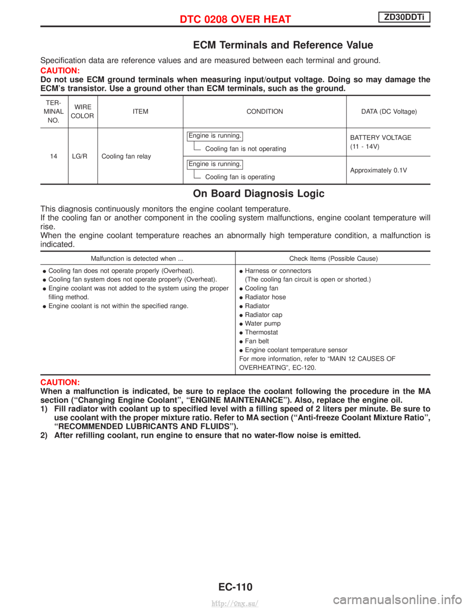
ECM Terminals and Reference Value
Specification data are reference values and are measured between each terminal and ground.
CAUTION:
Do not use ECM ground terminals when measuring input/output voltage. Doing so may damage the
ECM's transistor. Use a ground other than ECM terminals, such as the ground.
TER-
MINAL NO. WIRE
COLOR ITEM CONDITION DATA (DC Voltage)
14 LG/R Cooling fan relay Engine is running.
Cooling fan is not operating
BATTERY VOLTAGE
(11 - 14V)
Engine is running.
Cooling fan is operating Approximately 0.1V
On Board Diagnosis Logic
This diagnosis continuously monitors the engine coolant temperature.
If the cooling fan or another component in the cooling system malfunctions, engine coolant temperature will
rise.
When the engine coolant temperature reaches an abnormally high temperature condition, a malfunction is
indicated.
Malfunction is detected when ...
Check Items (Possible Cause)
I Cooling fan does not operate properly (Overheat).
I Cooling fan system does not operate properly (Overheat).
I Engine coolant was not added to the system using the proper
filling method.
I Engine coolant is not within the specified range. I
Harness or connectors
(The cooling fan circuit is open or shorted.)
I Cooling fan
I Radiator hose
I Radiator
I Radiator cap
I Water pump
I Thermostat
I Fan belt
I Engine coolant temperature sensor
For more information, refer to ªMAIN 12 CAUSES OF
OVERHEATINGº, EC-120.
CAUTION:
When a malfunction is indicated, be sure to replace the coolant following the procedure in the MA
section (ªChanging Engine Coolantº, ªENGINE MAINTENANCEº). Also, replace the engine oil.
1) Fill radiator with coolant up to specified level with a filling speed of 2 liters per minute. Be sure to use coolant with the proper mixture ratio. Refer to MA section (ªAnti-freeze Coolant Mixture Ratioº,
ªRECOMMENDED LUBRICANTS AND FLUIDSº).
2) After refilling coolant, run engine to ensure that no water-flow noise is emitted.
DTC 0208 OVER HEATZD30DDTi
EC-110
http://vnx.su/
Page 395 of 1833
18 CHECK MAIN 12 CAUSES
If the cause cannot be isolated, go to ªMAIN 12 CAUSES OF OVERHEATINGº, EC-120.EINSPECTION END
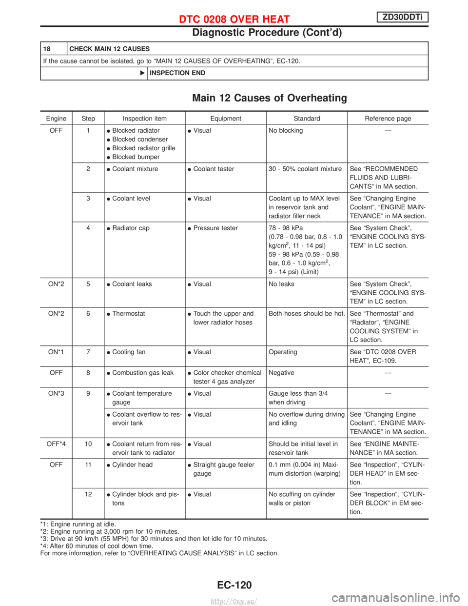
Main 12 Causes of Overheating
Engine Step Inspection item EquipmentStandardReference page
OFF 1 IBlocked radiator
I Blocked condenser
I Blocked radiator grille
I Blocked bumper I
Visual No blocking Ð
2 ICoolant mixture ICoolant tester 30 - 50% coolant mixture See ªRECOMMENDED
FLUIDS AND LUBRI-
CANTSº in MA section.
3 ICoolant level IVisual Coolant up to MAX level
in reservoir tank and
radiator filler neck See ªChanging Engine
Coolantº, ªENGINE MAIN-
TENANCEº in MA section.
4 IRadiator cap IPressure tester 78 - 98 kPa
(0.78 - 0.98 bar, 0.8 - 1.0
kg/cm
2, 11 - 14 psi)
59 - 98 kPa (0.59 - 0.98
bar, 0.6 - 1.0 kg/cm
2,
9 - 14 psi) (Limit) See ªSystem Checkº,
ªENGINE COOLING SYS-
TEMº in LC section.
ON*2 5 ICoolant leaks IVisual No leaks See ªSystem Checkº,
ªENGINE COOLING SYS-
TEMº in LC section.
ON*2 6 IThermostat ITouch the upper and
lower radiator hoses Both hoses should be hot. See ªThermostatº and
ªRadiatorº, ªENGINE
COOLING SYSTEMº in
LC section.
ON*1 7 ICooling fan IVisual Operating See ªDTC 0208 OVER
HEATº, EC-109.
OFF 8 ICombustion gas leak IColor checker chemical
tester 4 gas analyzer Negative Ð
ON*3 9 ICoolant temperature
gauge I
Visual Gauge less than 3/4
when driving Ð
I Coolant overflow to res-
ervoir tank I
Visual No overflow during driving
and idling See ªChanging Engine
Coolantº, ªENGINE MAIN-
TENANCEº in MA section.
OFF*4 10 ICoolant return from res-
ervoir tank to radiator I
Visual Should be initial level in
reservoir tank See ªENGINE MAINTE-
NANCEº in MA section.
OFF 11 ICylinder head IStraight gauge feeler
gauge 0.1 mm (0.004 in) Maxi-
mum distortion (warping) See ªInspectionº, ªCYLIN-
DER HEADº in EM sec-
tion.
12 ICylinder block and pis-
tons I
Visual No scuffing on cylinder
walls or piston See ªInspectionº, ªCYLIN-
DER BLOCKº in EM sec-
tion.
*1: Engine running at idle.
*2: Engine running at 3,000 rpm for 10 minutes.
*3: Drive at 90 km/h (55 MPH) for 30 minutes and then let idle for 10 minutes.
*4: After 60 minutes of cool down time.
For more information, refer to ªOVERHEATING CAUSE ANALYSISº in LC section.
DTC 0208 OVER HEATZD30DDTi
Diagnostic Procedure (Cont'd)
EC-120
http://vnx.su/
Page 716 of 1833
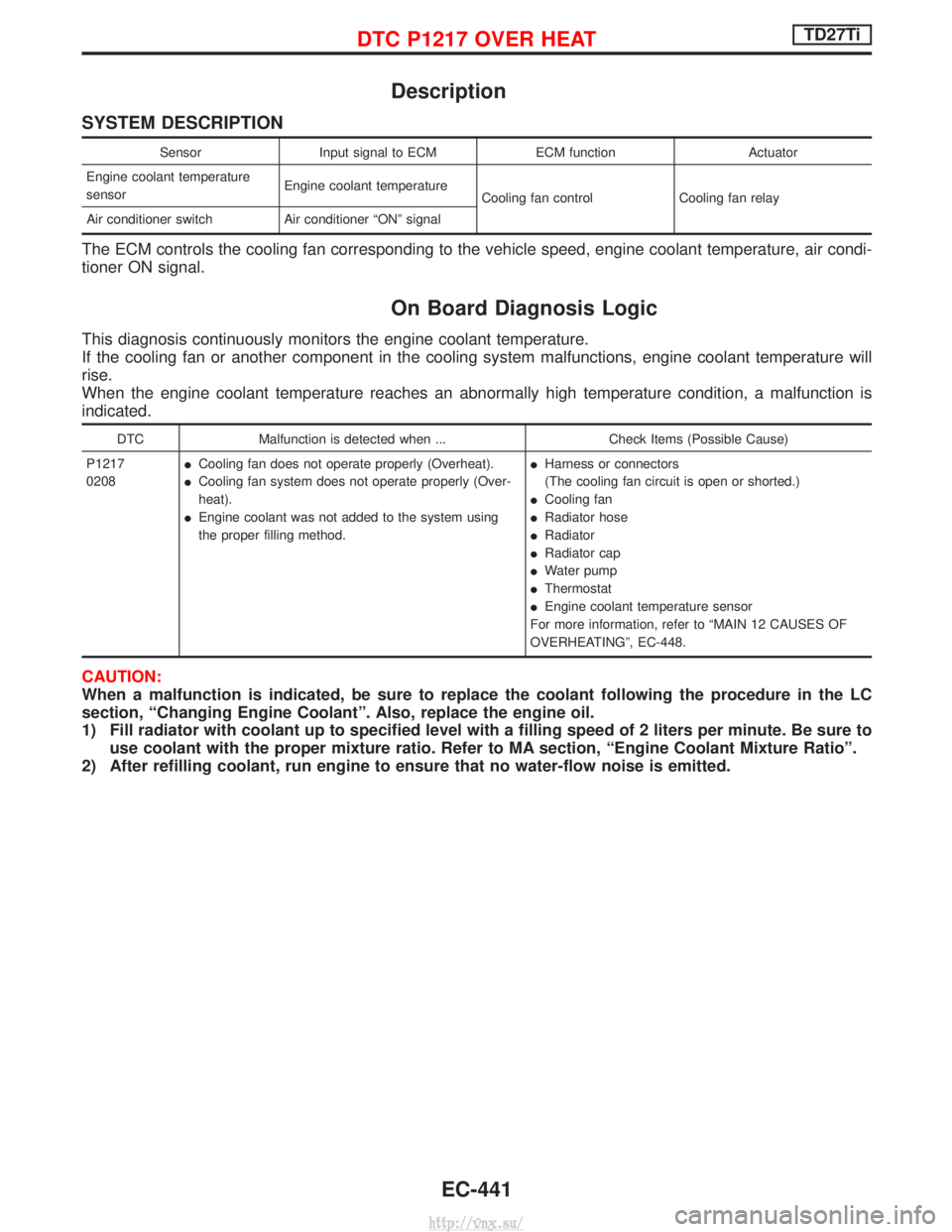
Description
SYSTEM DESCRIPTION
SensorInput signal to ECM ECM functionActuator
Engine coolant temperature
sensor Engine coolant temperature
Cooling fan control Cooling fan relay
Air conditioner switch Air conditioner ªONº signal
The ECM controls the cooling fan corresponding to the vehicle speed, engine coolant temperature, air condi-
tioner ON signal.
On Board Diagnosis Logic
This diagnosis continuously monitors the engine coolant temperature.
If the cooling fan or another component in the cooling system malfunctions, engine coolant temperature will
rise.
When the engine coolant temperature reaches an abnormally high temperature condition, a malfunction is
indicated.
DTC Malfunction is detected when ... Check Items (Possible Cause)
P1217
0208 I
Cooling fan does not operate properly (Overheat).
I Cooling fan system does not operate properly (Over-
heat).
I Engine coolant was not added to the system using
the proper filling method. I
Harness or connectors
(The cooling fan circuit is open or shorted.)
I Cooling fan
I Radiator hose
I Radiator
I Radiator cap
I Water pump
I Thermostat
I Engine coolant temperature sensor
For more information, refer to ªMAIN 12 CAUSES OF
OVERHEATINGº, EC-448.
CAUTION:
When a malfunction is indicated, be sure to replace the coolant following the procedure in the LC
section, ªChanging Engine Coolantº. Also, replace the engine oil.
1) Fill radiator with coolant up to specified level with a filling speed of 2 liters per minute. Be sure to use coolant with the proper mixture ratio. Refer to MA section, ªEngine Coolant Mixture Ratioº.
2) After refilling coolant, run engine to ensure that no water-flow noise is emitted.
DTC P1217 OVER HEATTD27Ti
EC-441
http://vnx.su/
Page 722 of 1833
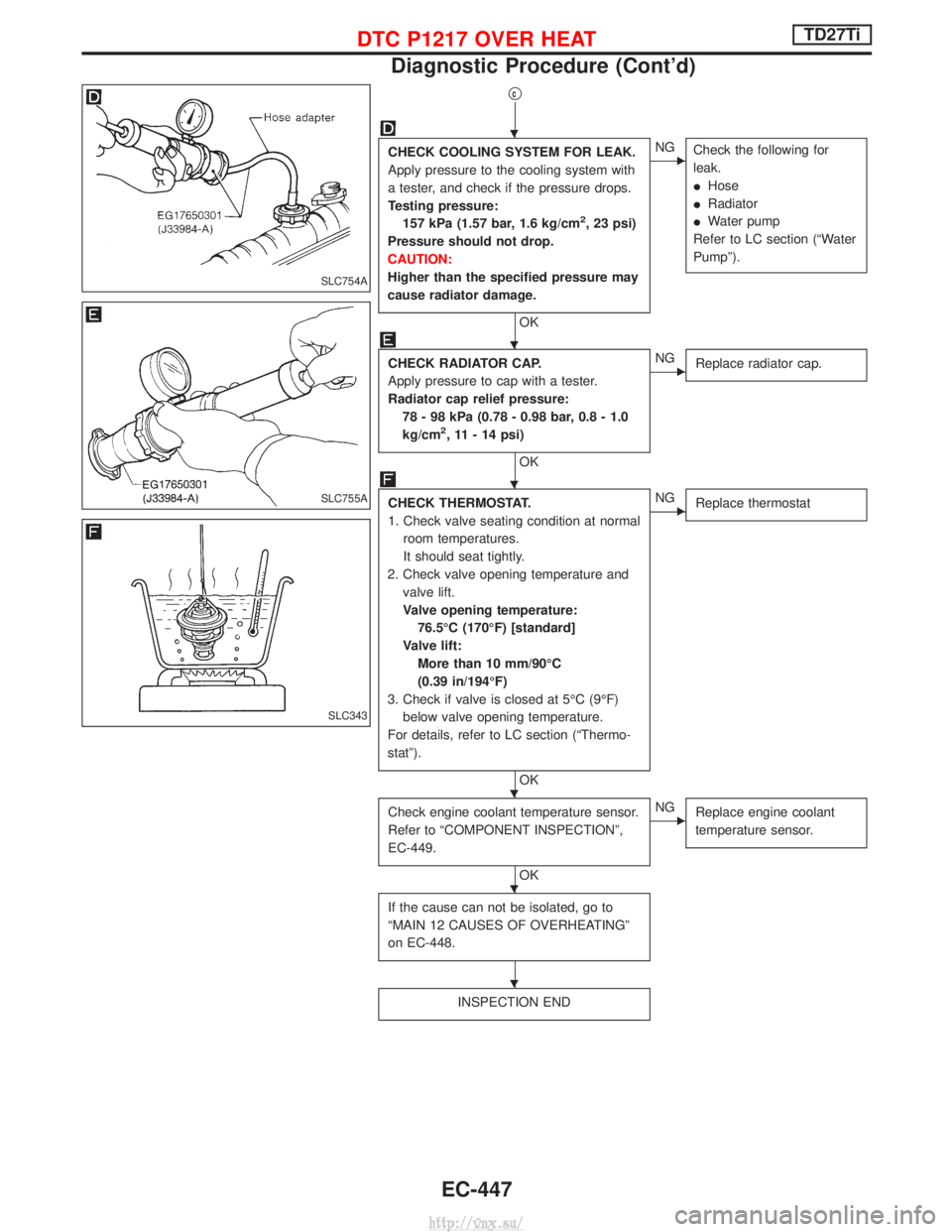
qc
CHECK COOLING SYSTEM FOR LEAK.
Apply pressure to the cooling system with
a tester, and check if the pressure drops.
Testing pressure:157 kPa (1.57 bar, 1.6 kg/cm
2, 23 psi)
Pressure should not drop.
CAUTION:
Higher than the specified pressure may
cause radiator damage.
OK
ENG Check the following for
leak.
IHose
I Radiator
I Water pump
Refer to LC section (ªWater
Pumpº).
CHECK RADIATOR CAP.
Apply pressure to cap with a tester.
Radiator cap relief pressure: 78 - 98 kPa (0.78 - 0.98 bar, 0.8 - 1.0
kg/cm
2, 11 - 14 psi)
OK
ENG Replace radiator cap.
CHECK THERMOSTAT.
1. Check valve seating condition at normal
room temperatures.
It should seat tightly.
2. Check valve opening temperature and valve lift.
Valve opening temperature:76.5ÉC (170ÉF) [standard]
Valve lift: More than 10 mm/90ÉC
(0.39 in/194ÉF)
3. Check if valve is closed at 5ÉC (9ÉF) below valve opening temperature.
For details, refer to LC section (ªThermo-
statº).
OK
ENG Replace thermostat
Check engine coolant temperature sensor.
Refer to ªCOMPONENT INSPECTIONº,
EC-449.
OK
ENGReplace engine coolant
temperature sensor.
If the cause can not be isolated, go to
ªMAIN 12 CAUSES OF OVERHEATINGº
on EC-448.
INSPECTION END
SLC754A
SLC755A
SLC343
H
H
H
H
H
H
DTC P1217 OVER HEATTD27Ti
Diagnostic Procedure (Cont'd)
EC-447
http://vnx.su/
Page 723 of 1833
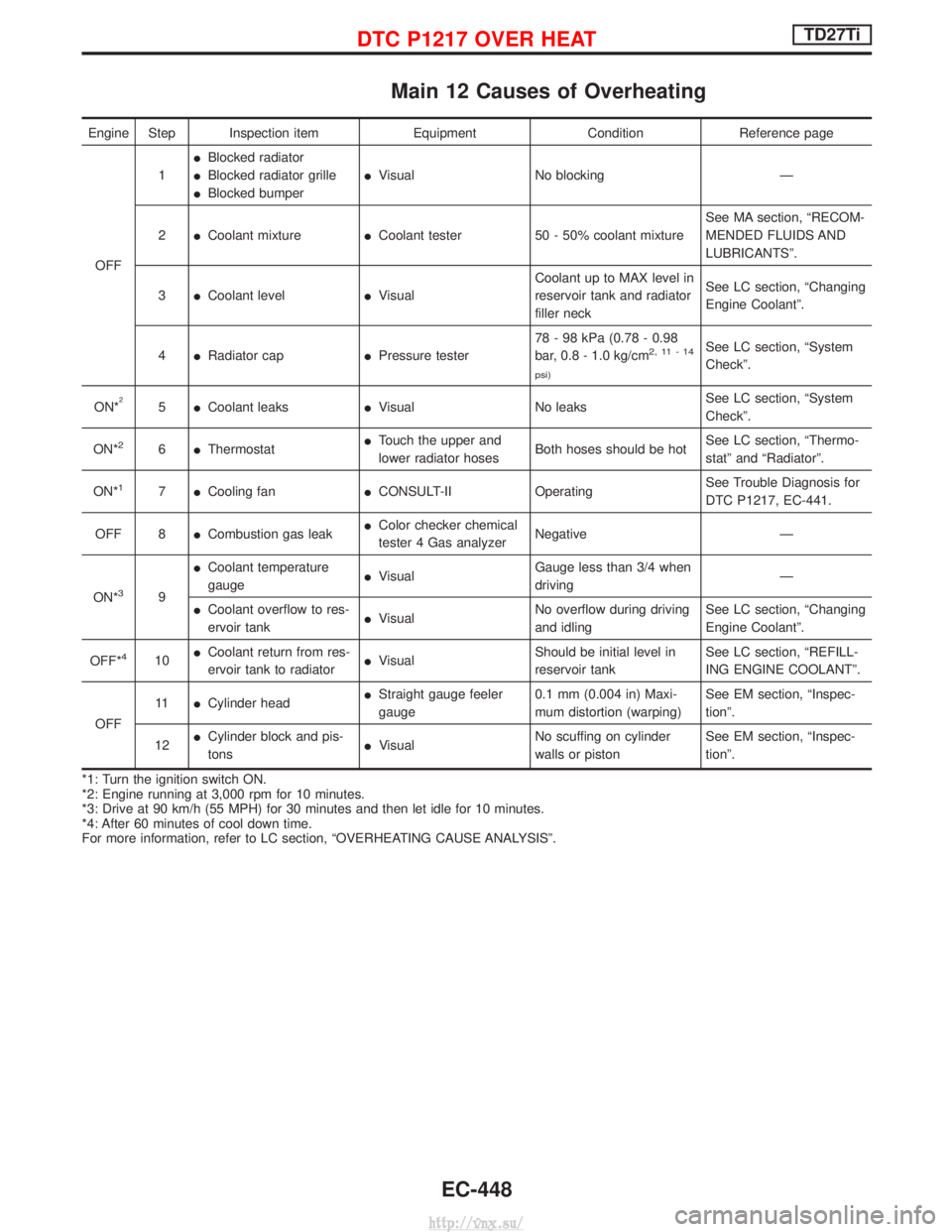
Main 12 Causes of Overheating
Engine Step Inspection itemEquipmentConditionReference page
OFF 1
I
Blocked radiator
I Blocked radiator grille
I Blocked bumper I
Visual No blocking Ð
2 ICoolant mixture ICoolant tester 50 - 50% coolant mixture See MA section, ªRECOM-
MENDED FLUIDS AND
LUBRICANTSº.
3 ICoolant level IVisual Coolant up to MAX level in
reservoir tank and radiator
filler neck See LC section, ªChanging
Engine Coolantº.
4 IRadiator cap IPressure tester 78 - 98 kPa (0.78 - 0.98
bar, 0.8 - 1.0 kg/cm
2,11-14
psi)See LC section, ªSystem
Checkº.
ON*
25 ICoolant leaks IVisual No leaks See LC section, ªSystem
Checkº.
ON*
26 IThermostat I
Touch the upper and
lower radiator hoses Both hoses should be hot See LC section, ªThermo-
statº and ªRadiatorº.
ON*
17 ICooling fan ICONSULT-II Operating See Trouble Diagnosis for
DTC P1217, EC-441.
OFF 8 ICombustion gas leak I
Color checker chemical
tester 4 Gas analyzer Negative Ð
ON*
39 I
Coolant temperature
gauge I
Visual Gauge less than 3/4 when
driving Ð
I Coolant overflow to res-
ervoir tank I
Visual No overflow during driving
and idling See LC section, ªChanging
Engine Coolantº.
OFF*
410 I
Coolant return from res-
ervoir tank to radiator I
Visual Should be initial level in
reservoir tank See LC section, ªREFILL-
ING ENGINE COOLANTº.
OFF 11
ICylinder head I
Straight gauge feeler
gauge 0.1 mm (0.004 in) Maxi-
mum distortion (warping) See EM section, ªInspec-
tionº.
12 I
Cylinder block and pis-
tons I
Visual No scuffing on cylinder
walls or piston See EM section, ªInspec-
tionº.
*1: Turn the ignition switch ON.
*2: Engine running at 3,000 rpm for 10 minutes.
*3: Drive at 90 km/h (55 MPH) for 30 minutes and then let idle for 10 minutes.
*4: After 60 minutes of cool down time.
For more information, refer to LC section, ªOVERHEATING CAUSE ANALYSISº.
DTC P1217 OVER HEATTD27Ti
EC-448
http://vnx.su/