exhaust NISSAN TIIDA 2008 Service Owners Manual
[x] Cancel search | Manufacturer: NISSAN, Model Year: 2008, Model line: TIIDA, Model: NISSAN TIIDA 2008Pages: 2771, PDF Size: 60.61 MB
Page 2269 of 2771
PERIODIC MAINTENANCE
MA-9
< SERVICE INFORMATION >
C
D
E
F
G
H
I
J
K
MA
B
MA
N
O
P
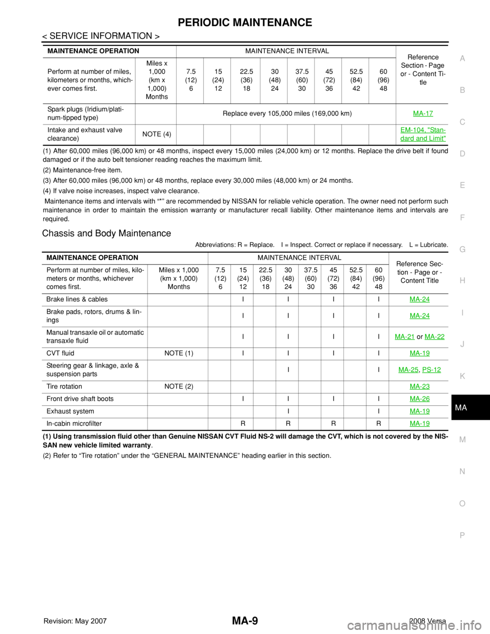
(1) After 60,000 miles (96,000 km) or 48 months, inspect every 15,000 miles (24,000 km) or 12 months. Replace the drive belt if found
damaged or if the auto belt tensioner reading reaches the maximum limit.
(2) Maintenance-free item.
(3) After 60,000 miles (96,000 km) or 48 months, replace every 30,000 miles (48,000 km) or 24 months.
(4) If valve noise increases, inspect valve clearance.
Maintenance items and intervals with “*” are recommended by NISSAN for reliable vehicle operation. The owner need not perform such
maintenance in order to maintain the emission warranty or manufacturer recall liability. Other maintenance items and intervals are
required.
Chassis and Body Maintenance
Abbreviations: R = Replace. I = Inspect. Correct or replace if necessary. L = Lubricate.
(1) Using transmission fluid other than Genuine NISSAN CVT Fluid NS-2 will damage the CVT, which is not covered by the NIS-
SAN new vehicle limited warranty.
(2) Refer to “Tire rotation” under the “GENERAL MAINTENANCE” heading earlier in this section. Spark plugs (Iridium/plati-
num-tipped type)Replace every 105,000 miles (169,000 km)MA-17
Intake and exhaust valve
clearance)NOTE (4)EM-104, "Sta n-
dard and Limit"
MAINTENANCE OPERATIONMAINTENANCE INTERVAL
Reference
Section - Page
or - Content Ti-
tle Perform at number of miles,
kilometers or months, which-
ever comes first.Miles x
1,000
(km x
1,000)
Months7.5
(12)
615
(24)
1222.5
(36)
1830
(48)
2437.5
(60)
3045
(72)
3652.5
(84)
4260
(96)
48
MAINTENANCE OPERATIONMAINTENANCE INTERVAL
Reference Sec-
tion - Page or -
Content Title Perform at number of miles, kilo-
meters or months, whichever
comes first.Miles x 1,000
(km x 1,000)
Months7.5
(12)
615
(24)
1222.5
(36)
1830
(48)
2437.5
(60)
3045
(72)
3652.5
(84)
4260
(96)
48
Brake lines & cables I I I IMA-24
Brake pads, rotors, drums & lin-
ings IIIIMA-24
Manual transaxle oil or automatic
transaxle fluidIIIIMA-21 or MA-22
CVT fluid NOTE (1) IIIIMA-19
Steering gear & linkage, axle &
suspension partsIIMA-25, PS-12
Tire rotation NOTE (2)MA-23
Front drive shaft boots I I I IMA-26
Exhaust system I IMA-19
In-cabin microfilter R R R RMA-19
Page 2279 of 2771
CHASSIS AND BODY MAINTENANCE
MA-19
< SERVICE INFORMATION >
C
D
E
F
G
H
I
J
K
MA
B
MA
N
O
P
CHASSIS AND BODY MAINTENANCE
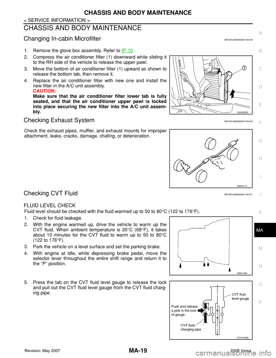
Changing In-cabin MicrofilterINFOID:0000000001704739
1. Remove the glove box assembly. Refer to IP-10 .
2. Compress the air conditioner filter (1) downward while sliding it
to the RH side of the vehicle to release the upper pawl.
3. Move the bottom of air conditioner filter (1) upward as shown to
release the bottom tab, then remove it.
4. Replace the air conditioner filter with new one and install the
new filter in the A/C unit assembly.
CAUTION:
Make sure that the air conditioner filter lower tab is fully
seated, and that the air conditioner upper pawl is locked
into place securing the new filter into the A/C unit assem-
bly.
Checking Exhaust SystemINFOID:0000000001704740
Check the exhaust pipes, muffler, and exhaust mounts for improper
attachment, leaks, cracks, damage, chafing, or deterioration.
Checking CVT FluidINFOID:0000000001704741
FLUID LEVEL CHECK
Fluid level should be checked with the fluid warmed up to 50 to 80°C (122 to 176°F).
1. Check for fluid leakage.
2. With the engine warmed up, drive the vehicle to warm up the
CVT fluid. When ambient temperature is 20°C (68°F), it takes
about 10 minutes for the CVT fluid to warm up to 50 to 80°C
(122 to 176°F).
3. Park the vehicle on a level surface and set the parking brake.
4. With engine at idle, while depressing brake pedal, move the
selector lever throughout the entire shift range and return it to
the “P” position.
5. Press the tab on the CVT fluid level gauge to release the lock
and pull out the CVT fluid level gauge from the CVT fluid charg-
ing pipe.
SJIA0652E
SMA211A
SMA146B
SCIA1933E
Page 2302 of 2771
MT-14
< SERVICE INFORMATION >
CONTROL LINKAGE
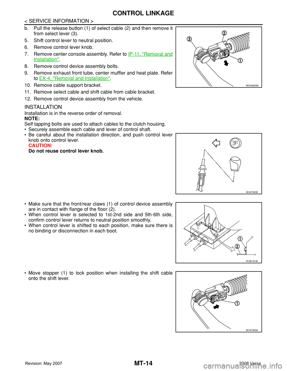
b. Pull the release button (1) of select cable (2) and then remove it
from select lever (3).
5. Shift control lever to neutral position.
6. Remove control lever knob.
7. Remove center console assembly. Refer to IP-11, "
Removal and
Installation".
8. Remove control device assembly bolts.
9. Remove exhaust front tube, center muffler and heat plate. Refer
to EX-4, "
Removal and Installation".
10. Remove cable support bracket.
11. Remove select cable and shift cable from cable bracket.
12. Remove control device assembly from the vehicle.
INSTALLATION
Installation is in the reverse order of removal.
NOTE:
Self tapping bolts are used to attach cables to the clutch housing.
• Securely assemble each cable and lever of control shaft.
• Be careful about the installation direction, and push control lever
knob onto control lever.
CAUTION:
Do not reuse control lever knob.
• Make sure that the front/rear claws (1) of control device assembly
are in contact with flange of the floor (2).
• When control lever is selected to 1st-2nd side and 5th-6th side,
confirm control lever returns to neutral position smoothly.
• When control lever is shifted to each position, make sure there is
no binding or disconnection in each boot.
• Move stopper (1) to lock position when installing the shift cable
onto the shift lever.
WCIA0606E
SCIA7630E
PCIB1510E
SCIA7846E
Page 2347 of 2771
PRECAUTIONS
MTC-9
< SERVICE INFORMATION >
C
D
E
F
G
H
I
K
L
MA
B
MTC
N
O
P
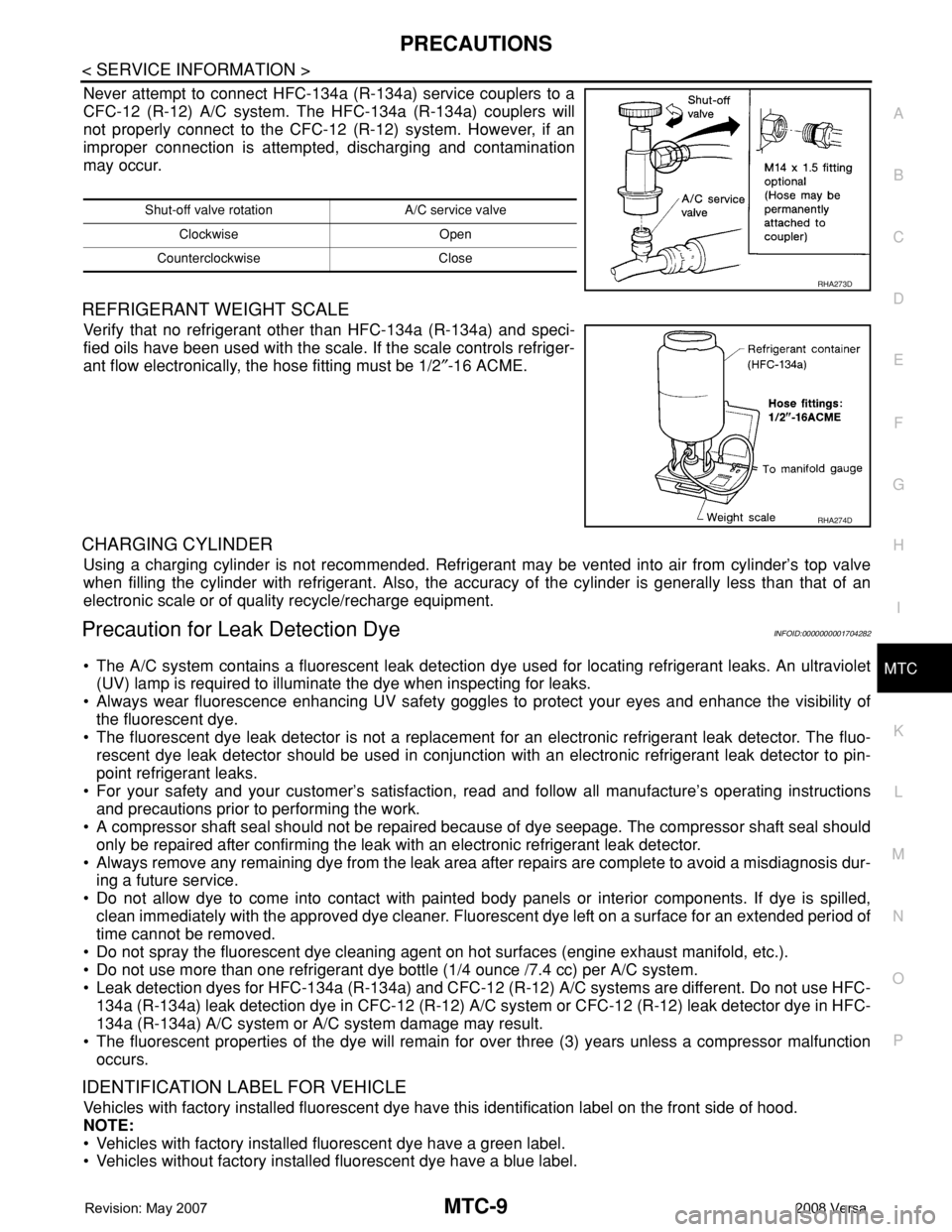
Never attempt to connect HFC-134a (R-134a) service couplers to a
CFC-12 (R-12) A/C system. The HFC-134a (R-134a) couplers will
not properly connect to the CFC-12 (R-12) system. However, if an
improper connection is attempted, discharging and contamination
may occur.
REFRIGERANT WEIGHT SCALE
Verify that no refrigerant other than HFC-134a (R-134a) and speci-
fied oils have been used with the scale. If the scale controls refriger-
ant flow electronically, the hose fitting must be 1/2″-16 ACME.
CHARGING CYLINDER
Using a charging cylinder is not recommended. Refrigerant may be vented into air from cylinder’s top valve
when filling the cylinder with refrigerant. Also, the accuracy of the cylinder is generally less than that of an
electronic scale or of quality recycle/recharge equipment.
Precaution for Leak Detection DyeINFOID:0000000001704282
• The A/C system contains a fluorescent leak detection dye used for locating refrigerant leaks. An ultraviolet
(UV) lamp is required to illuminate the dye when inspecting for leaks.
• Always wear fluorescence enhancing UV safety goggles to protect your eyes and enhance the visibility of
the fluorescent dye.
• The fluorescent dye leak detector is not a replacement for an electronic refrigerant leak detector. The fluo-
rescent dye leak detector should be used in conjunction with an electronic refrigerant leak detector to pin-
point refrigerant leaks.
• For your safety and your customer’s satisfaction, read and follow all manufacture’s operating instructions
and precautions prior to performing the work.
• A compressor shaft seal should not be repaired because of dye seepage. The compressor shaft seal should
only be repaired after confirming the leak with an electronic refrigerant leak detector.
• Always remove any remaining dye from the leak area after repairs are complete to avoid a misdiagnosis dur-
ing a future service.
• Do not allow dye to come into contact with painted body panels or interior components. If dye is spilled,
clean immediately with the approved dye cleaner. Fluorescent dye left on a surface for an extended period of
time cannot be removed.
• Do not spray the fluorescent dye cleaning agent on hot surfaces (engine exhaust manifold, etc.).
• Do not use more than one refrigerant dye bottle (1/4 ounce /7.4 cc) per A/C system.
• Leak detection dyes for HFC-134a (R-134a) and CFC-12 (R-12) A/C systems are different. Do not use HFC-
134a (R-134a) leak detection dye in CFC-12 (R-12) A/C system or CFC-12 (R-12) leak detector dye in HFC-
134a (R-134a) A/C system or A/C system damage may result.
• The fluorescent properties of the dye will remain for over three (3) years unless a compressor malfunction
occurs.
IDENTIFICATION LABEL FOR VEHICLE
Vehicles with factory installed fluorescent dye have this identification label on the front side of hood.
NOTE:
• Vehicles with factory installed fluorescent dye have a green label.
• Vehicles without factory installed fluorescent dye have a blue label.
Shut-off valve rotation A/C service valve
Clockwise Open
Counterclockwise Close
RHA273D
RHA274D
Page 2431 of 2771
PARKING BRAKE CONTROL
PB-5
< SERVICE INFORMATION >
C
D
E
G
H
I
J
K
L
MA
B
PB
N
O
P
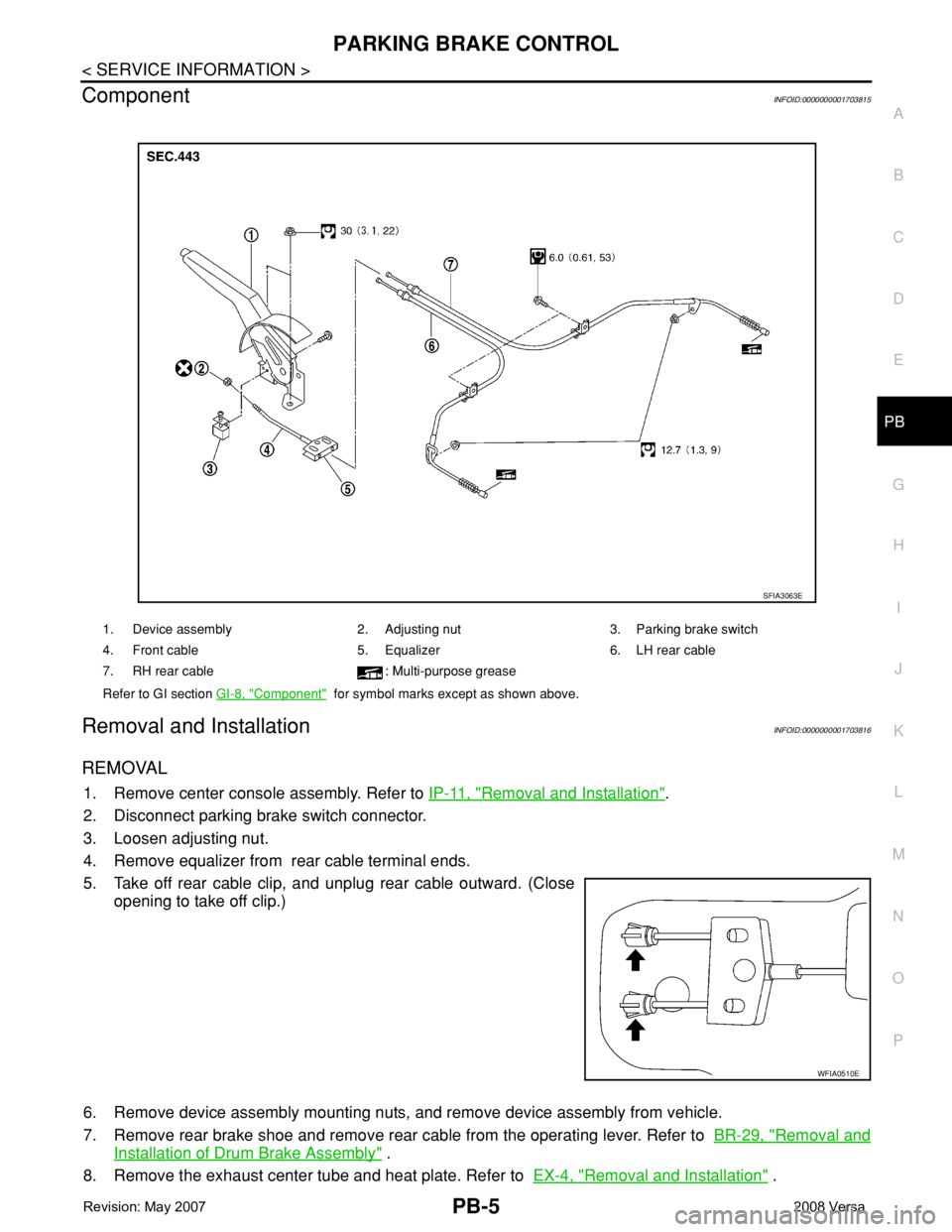
ComponentINFOID:0000000001703815
Removal and InstallationINFOID:0000000001703816
REMOVAL
1. Remove center console assembly. Refer to IP-11, "Removal and Installation".
2. Disconnect parking brake switch connector.
3. Loosen adjusting nut.
4. Remove equalizer from rear cable terminal ends.
5. Take off rear cable clip, and unplug rear cable outward. (Close
opening to take off clip.)
6. Remove device assembly mounting nuts, and remove device assembly from vehicle.
7. Remove rear brake shoe and remove rear cable from the operating lever. Refer to BR-29, "
Removal and
Installation of Drum Brake Assembly" .
8. Remove the exhaust center tube and heat plate. Refer to EX-4, "
Removal and Installation" .
1. Device assembly 2. Adjusting nut 3. Parking brake switch
4. Front cable 5. Equalizer 6. LH rear cable
7. RH rear cable : Multi-purpose grease
Refer to GI section GI-8, "
Component" for symbol marks except as shown above.
SFIA3063E
WFIA0510E