wheel NISSAN TIIDA 2008 Service Repair Manual
[x] Cancel search | Manufacturer: NISSAN, Model Year: 2008, Model line: TIIDA, Model: NISSAN TIIDA 2008Pages: 2771, PDF Size: 60.61 MB
Page 2569 of 2771
RSU-10
< SERVICE INFORMATION >
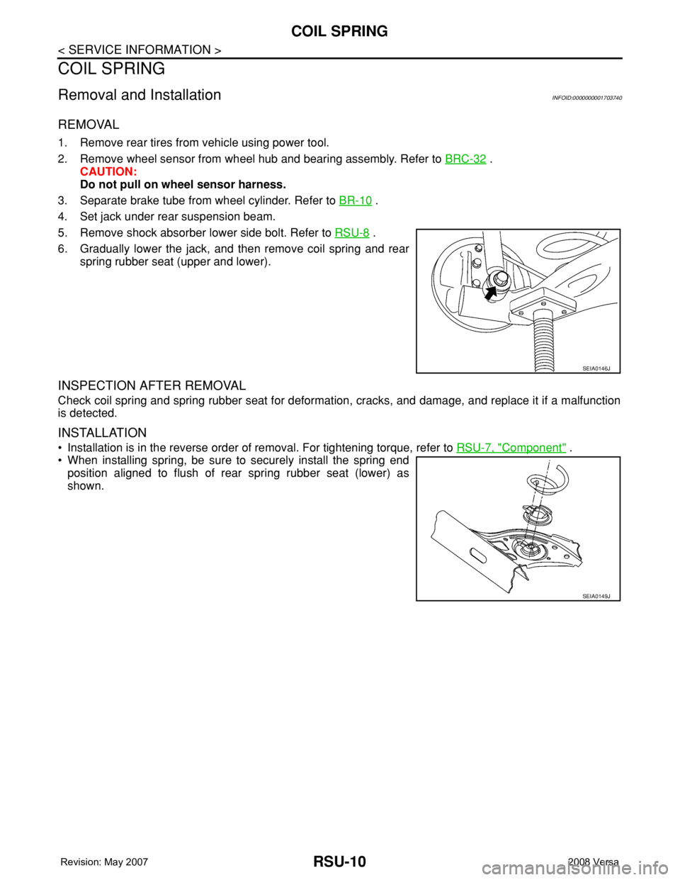
COIL SPRING
COIL SPRING
Removal and InstallationINFOID:0000000001703740
REMOVAL
1. Remove rear tires from vehicle using power tool.
2. Remove wheel sensor from wheel hub and bearing assembly. Refer to BRC-32
.
CAUTION:
Do not pull on wheel sensor harness.
3. Separate brake tube from wheel cylinder. Refer to BR-10
.
4. Set jack under rear suspension beam.
5. Remove shock absorber lower side bolt. Refer to RSU-8
.
6. Gradually lower the jack, and then remove coil spring and rear
spring rubber seat (upper and lower).
INSPECTION AFTER REMOVAL
Check coil spring and spring rubber seat for deformation, cracks, and damage, and replace it if a malfunction
is detected.
INSTALLATION
• Installation is in the reverse order of removal. For tightening torque, refer to RSU-7, "Component" .
• When installing spring, be sure to securely install the spring end
position aligned to flush of rear spring rubber seat (lower) as
shown.
SEIA0146J
SEIA0149J
Page 2570 of 2771
REAR SUSPENSION BEAM
RSU-11
< SERVICE INFORMATION >
C
D
F
G
H
I
J
K
L
MA
B
RSU
N
O
P
REAR SUSPENSION BEAM
Removal and InstallationINFOID:0000000001703741
REMOVAL
1. Remove rear tires from vehicle using power tool.
2. Separate parking brake rear cable from rear drum brake and rear suspension beam. Refer to PB-4
.
3. Remove wheel sensor and wheel sensor harness from wheel hub and bearing assembly and rear suspen-
sion beam. Refer to BRC-32
.
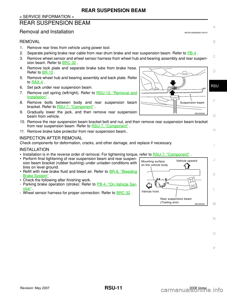
4. Remove lock plate and separate brake tube from brake hose.
Refer to BR-10
.
5. Remove wheel hub and bearing assembly and back plate. Refer
to RAX-4
.
6. Set jack under rear suspension beam.
7. Remove coil spring (left/right). Refer to RSU-10, "
Removal and
Installation" .
8. Remove bolts between body and rear suspension beam
bracket. Refer to RSU-7, "
Component" .
9. Gradually lower the jack, and then remove rear suspension
beam from vehicle.
10. Remove the rear suspension beam bracket bolt and nut, and then remove rear suspension beam bracket
from rear suspension beam. Refer to RSU-7, "
Component" .
11. Remove brake tube protector from rear suspension beam..
INSPECTION AFTER REMOVAL
Check components for deformation, cracks, and other damage, and replace if necessary.
INSTALLATION
• Installation is in the reverse order of removal. For tightening torque, refer to RSU-7, "Component" .
• Perform final tightening of rear suspension beam and rear suspen-
sion beam bracket (rubber bushing) under unladen conditions with
tires on level ground.
• Refill with new brake fluid and bleed air. Refer to BR-8, "
Bleeding
Brake System" .
• Check the following after finishing work.
- Parking brake operation (stroke): Refer to PB-4, "
On-Vehicle Ser-
vice" .
- Wheel sensor harness for proper connection: Refer to BRC-32
.
MEIA0029E
MEIA0030E
Page 2571 of 2771
RSU-12
< SERVICE INFORMATION >
SERVICE DATA AND SPECIFICATIONS (SDS)
SERVICE DATA AND SPECIFICATIONS (SDS)
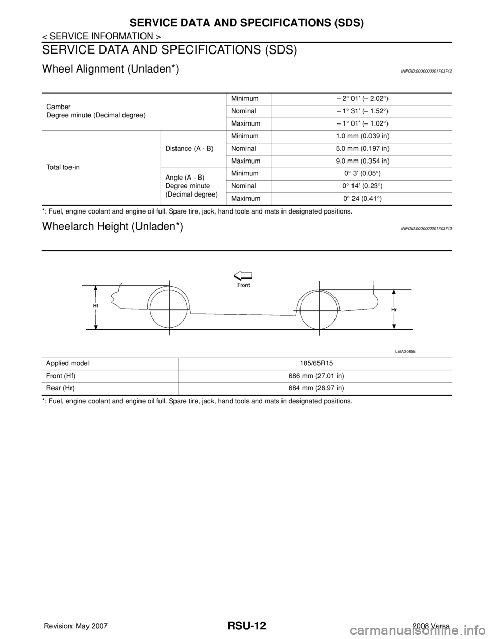
Wheel Alignment (Unladen*)INFOID:0000000001703742
*: Fuel, engine coolant and engine oil full. Spare tire, jack, hand tools and mats in designated positions.
Wheelarch Height (Unladen*)INFOID:0000000001703743
*: Fuel, engine coolant and engine oil full. Spare tire, jack, hand tools and mats in designated positions.Camber
Degree minute (Decimal degree)Minimum – 2° 01′ (– 2.02°)
Nominal – 1° 31′ (– 1.52°)
Maximum – 1° 01′ (– 1.02°)
Total toe-inDistance (A - B)Minimum 1.0 mm (0.039 in)
Nominal 5.0 mm (0.197 in)
Maximum 9.0 mm (0.354 in)
Angle (A - B)
Degree minute
(Decimal degree)Minimum 0° 3′ (0.05°)
Nominal 0° 14′ (0.23°)
Maximum 0° 24 (0.41°)
Applied model 185/65R15
Front (Hf) 686 mm (27.01 in)
Rear (Hr) 684 mm (26.97 in)
LEIA0085E
Page 2636 of 2771

SRS-2
< PRECAUTION >
PRECAUTIONS
PRECAUTION
PRECAUTIONS
Precaution for Supplemental Restraint System (SRS) "AIR BAG" and "SEAT BELT
PRE-TENSIONER"
INFOID:0000000001703904
The Supplemental Restraint System such as “AIR BAG” and “SEAT BELT PRE-TENSIONER”, used along
with a front seat belt, helps to reduce the risk or severity of injury to the driver and front passenger for certain
types of collision. This system includes seat belt switch inputs and dual stage front air bag modules. The SRS
system uses the seat belt switches to determine the front air bag deployment, and may only deploy one front
air bag, depending on the severity of a collision and whether the front occupants are belted or unbelted.
Information necessary to service the system safely is included in the SR and SB section of this Service Man-
ual.
WARNING:
• To avoid rendering the SRS inoperative, which could increase the risk of personal injury or death in
the event of a collision which would result in air bag inflation, all maintenance must be performed by
an authorized NISSAN/INFINITI dealer.
• Improper maintenance, including incorrect removal and installation of the SRS, can lead to personal
injury caused by unintentional activation of the system. For removal of Spiral Cable and Air Bag
Module, see the SR section.
• Do not use electrical test equipment on any circuit related to the SRS unless instructed to in this
Service Manual. SRS wiring harnesses can be identified by yellow and/or orange harnesses or har-
ness connectors.
Precaution for SRS "AIR BAG" and "SEAT BELT PRE-TENSIONER" Service
INFOID:0000000001703905
• Do not use electrical test equipment to check SRS circuits unless instructed to in this Service Manual.
• Before servicing the SRS, turn ignition switch OFF, disconnect both battery cables and wait at least 3 min-
utes.
For approximately 3 minutes after the cables are removed, it is still possible for the air bag and seat belt pre-
tensioner to deploy. Therefore, do not work on any SRS connectors or wires until at least 3 minutes have
passed.
• The air bag diagnosis sensor unit must always be installed with the arrow mark “⇐” pointing toward the front
of the vehicle for proper operation. Also check air bag diagnosis sensor unit for cracks, deformities or rust
before installation and replace as required.
• The spiral cable must be aligned with the neutral position since its rotations are limited. Do not attempt to
turn steering wheel or column after removal of steering gear.
• Handle air bag module carefully. Always place driver and front passenger air bag modules with the pad side
facing upward and seat mounted front side air bag module standing with the stud bolt side facing down.
• Conduct self-diagnosis to check entire SRS for proper function after replacing any components.
• After air bag inflates, the front instrument panel assembly should be replaced if damaged.
• Do not reuse center pillar upper garnish if removed.
Occupant Classification System PrecautionINFOID:0000000001703906
Replace control unit and passenger front seat cushion as an assembly.
Page 2638 of 2771
SRS-4
< SYMPTOM DIAGNOSIS >
SUPPLEMENTAL RESTRAINT SYSTEM (SRS)
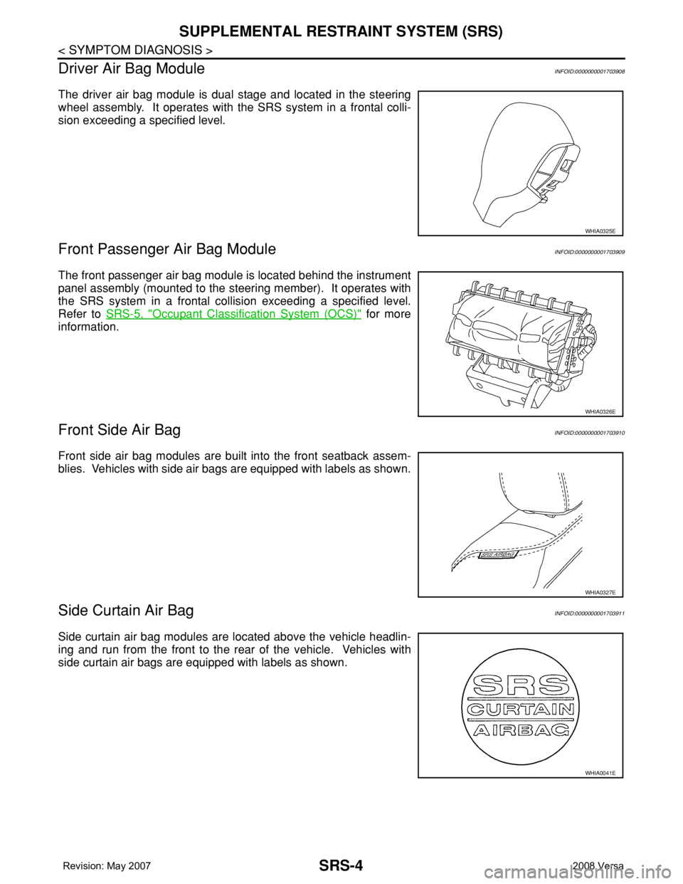
Driver Air Bag Module
INFOID:0000000001703908
The driver air bag module is dual stage and located in the steering
wheel assembly. It operates with the SRS system in a frontal colli-
sion exceeding a specified level.
Front Passenger Air Bag ModuleINFOID:0000000001703909
The front passenger air bag module is located behind the instrument
panel assembly (mounted to the steering member). It operates with
the SRS system in a frontal collision exceeding a specified level.
Refer to SRS-5, "
Occupant Classification System (OCS)" for more
information.
Front Side Air BagINFOID:0000000001703910
Front side air bag modules are built into the front seatback assem-
blies. Vehicles with side air bags are equipped with labels as shown.
Side Curtain Air BagINFOID:0000000001703911
Side curtain air bag modules are located above the vehicle headlin-
ing and run from the front to the rear of the vehicle. Vehicles with
side curtain air bags are equipped with labels as shown.
WHIA0325E
WHIA0326E
WHIA0327E
WHIA0041E
Page 2667 of 2771
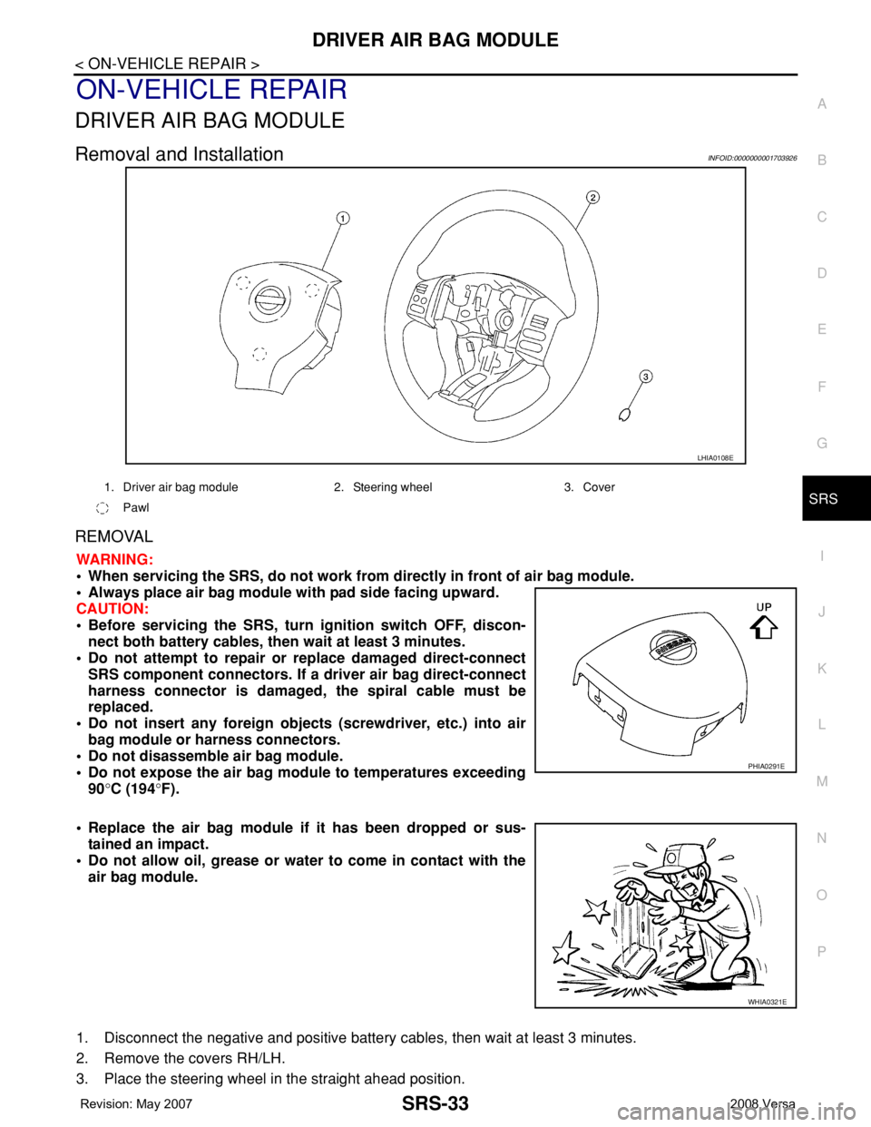
DRIVER AIR BAG MODULE
SRS-33
< ON-VEHICLE REPAIR >
C
D
E
F
G
I
J
K
L
MA
B
SRS
N
O
P
ON-VEHICLE REPAIR
DRIVER AIR BAG MODULE
Removal and InstallationINFOID:0000000001703926
REMOVAL
WARNING:
• When servicing the SRS, do not work from directly in front of air bag module.
• Always place air bag module with pad side facing upward.
CAUTION:
• Before servicing the SRS, turn ignition switch OFF, discon-
nect both battery cables, then wait at least 3 minutes.
• Do not attempt to repair or replace damaged direct-connect
SRS component connectors. If a driver air bag direct-connect
harness connector is damaged, the spiral cable must be
replaced.
• Do not insert any foreign objects (screwdriver, etc.) into air
bag module or harness connectors.
• Do not disassemble air bag module.
• Do not expose the air bag module to temperatures exceeding
90°C (194°F).
• Replace the air bag module if it has been dropped or sus-
tained an impact.
• Do not allow oil, grease or water to come in contact with the
air bag module.
1. Disconnect the negative and positive battery cables, then wait at least 3 minutes.
2. Remove the covers RH/LH.
3. Place the steering wheel in the straight ahead position.
LHIA0108E
1. Driver air bag module 2. Steering wheel 3. Cover
Pawl
PHIA0291E
WHIA0321E
Page 2668 of 2771
SRS-34
< ON-VEHICLE REPAIR >
DRIVER AIR BAG MODULE
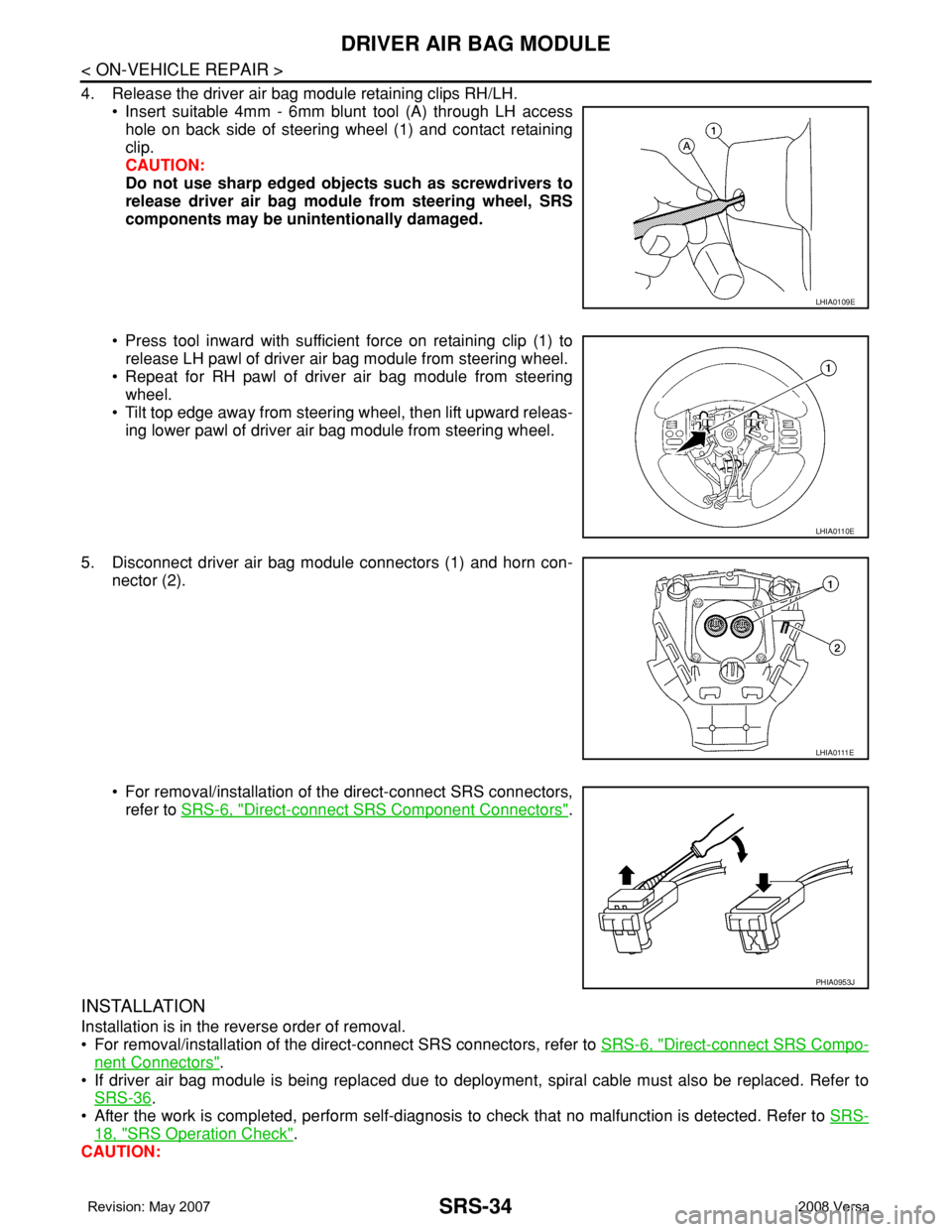
4. Release the driver air bag module retaining clips RH/LH.
• Insert suitable 4mm - 6mm blunt tool (A) through LH access
hole on back side of steering wheel (1) and contact retaining
clip.
CAUTION:
Do not use sharp edged objects such as screwdrivers to
release driver air bag module from steering wheel, SRS
components may be unintentionally damaged.
• Press tool inward with sufficient force on retaining clip (1) to
release LH pawl of driver air bag module from steering wheel.
• Repeat for RH pawl of driver air bag module from steering
wheel.
• Tilt top edge away from steering wheel, then lift upward releas-
ing lower pawl of driver air bag module from steering wheel.
5. Disconnect driver air bag module connectors (1) and horn con-
nector (2).
• For removal/installation of the direct-connect SRS connectors,
refer to SRS-6, "
Direct-connect SRS Component Connectors".
INSTALLATION
Installation is in the reverse order of removal.
• For removal/installation of the direct-connect SRS connectors, refer to SRS-6, "
Direct-connect SRS Compo-
nent Connectors".
• If driver air bag module is being replaced due to deployment, spiral cable must also be replaced. Refer to
SRS-36
.
• After the work is completed, perform self-diagnosis to check that no malfunction is detected. Refer to SRS-
18, "SRS Operation Check".
CAUTION:
LHIA0109E
LHIA0110E
LHIA0111E
PHIA0953J
Page 2670 of 2771
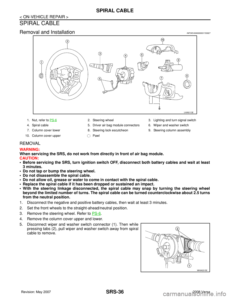
SRS-36
< ON-VEHICLE REPAIR >
SPIRAL CABLE
SPIRAL CABLE
Removal and InstallationINFOID:0000000001703927
REMOVAL
WARNING:
When servicing the SRS, do not work from directly in front of air bag module.
CAUTION:
• Before servicing the SRS, turn ignition switch OFF, disconnect both battery cables and wait at least
3 minutes.
• Do not tap or bump the steering wheel.
• Do not disassemble the spiral cable.
• Do not allow oil, grease or water to come in contact with the spiral cable.
• Replace the spiral cable if it has been dropped or sustained an impact.
• With the steering linkage disconnected, the spiral cable may snap by turning the steering wheel
beyond the limited number of turns. The spiral cable can be turned counterclockwise about 2.5 turns
from the neutral position.
1. Disconnect the negative and positive battery cables, then wait at least 3 minutes.
2. Set the front wheels to the straight-ahead/neutral position.
3. Remove the steering wheel. Refer to PS-6
.
4. Remove the column cover upper and lower.
5. Disconnect wiper and washer switch connector (1). Then while
pressing tabs (2), pull wiper and washer switch away from spiral
cable to remove.
LHIA0113E
1. Nut, refer to PS-62. Steering wheel 3. Lighting and turn signal switch
4. Spiral cable 5. Driver air bag module connectors 6. Wiper and washer switch
7. Column cover lower 8. Steering lock escutcheon 9. Steering column assembly
10. Column cover upper Pawl
WHIA0315E
Page 2671 of 2771
SPIRAL CABLE
SRS-37
< ON-VEHICLE REPAIR >
C
D
E
F
G
I
J
K
L
MA
B
SRS
N
O
P
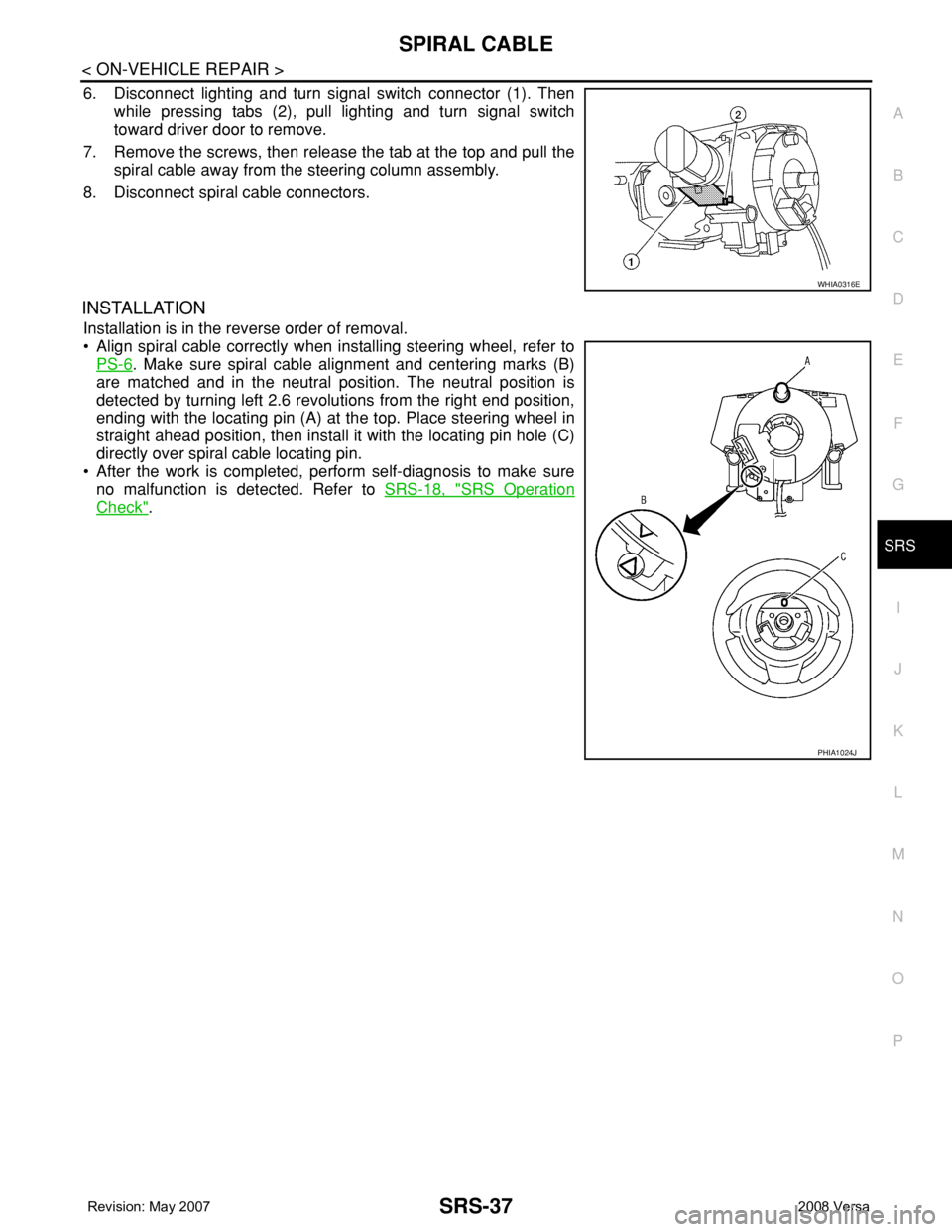
6. Disconnect lighting and turn signal switch connector (1). Then
while pressing tabs (2), pull lighting and turn signal switch
toward driver door to remove.
7. Remove the screws, then release the tab at the top and pull the
spiral cable away from the steering column assembly.
8. Disconnect spiral cable connectors.
INSTALLATION
Installation is in the reverse order of removal.
• Align spiral cable correctly when installing steering wheel, refer to
PS-6
. Make sure spiral cable alignment and centering marks (B)
are matched and in the neutral position. The neutral position is
detected by turning left 2.6 revolutions from the right end position,
ending with the locating pin (A) at the top. Place steering wheel in
straight ahead position, then install it with the locating pin hole (C)
directly over spiral cable locating pin.
• After the work is completed, perform self-diagnosis to make sure
no malfunction is detected. Refer to SRS-18, "
SRS Operation
Check".
WHIA0316E
PHIA1024J
Page 2680 of 2771
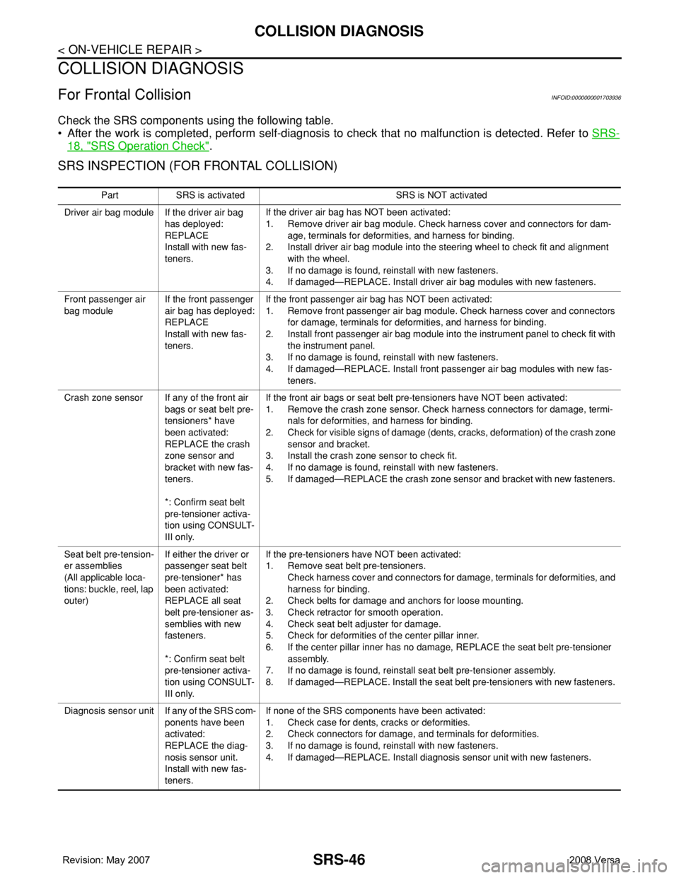
SRS-46
< ON-VEHICLE REPAIR >
COLLISION DIAGNOSIS
COLLISION DIAGNOSIS
For Frontal CollisionINFOID:0000000001703936
Check the SRS components using the following table.
• After the work is completed, perform self-diagnosis to check that no malfunction is detected. Refer to SRS-
18, "SRS Operation Check".
SRS INSPECTION (FOR FRONTAL COLLISION)
Part SRS is activated SRS is NOT activated
Driver air bag module If the driver air bag
has deployed:
REPLACE
Install with new fas-
teners.If the driver air bag has NOT been activated:
1. Remove driver air bag module. Check harness cover and connectors for dam-
age, terminals for deformities, and harness for binding.
2. Install driver air bag module into the steering wheel to check fit and alignment
with the wheel.
3. If no damage is found, reinstall with new fasteners.
4. If damaged—REPLACE. Install driver air bag modules with new fasteners.
Front passenger air
bag moduleIf the front passenger
air bag has deployed:
REPLACE
Install with new fas-
teners.If the front passenger air bag has NOT been activated:
1. Remove front passenger air bag module. Check harness cover and connectors
for damage, terminals for deformities, and harness for binding.
2. Install front passenger air bag module into the instrument panel to check fit with
the instrument panel.
3. If no damage is found, reinstall with new fasteners.
4. If damaged—REPLACE. Install front passenger air bag modules with new fas-
teners.
Crash zone sensor If any of the front air
bags or seat belt pre-
tensioners* have
been activated:
REPLACE the crash
zone sensor and
bracket with new fas-
teners.
*: Confirm seat belt
pre-tensioner activa-
tion using CONSULT-
III only.If the front air bags or seat belt pre-tensioners have NOT been activated:
1. Remove the crash zone sensor. Check harness connectors for damage, termi-
nals for deformities, and harness for binding.
2. Check for visible signs of damage (dents, cracks, deformation) of the crash zone
sensor and bracket.
3. Install the crash zone sensor to check fit.
4. If no damage is found, reinstall with new fasteners.
5. If damaged—REPLACE the crash zone sensor and bracket with new fasteners.
Seat belt pre-tension-
er assemblies
(All applicable loca-
tions: buckle, reel, lap
outer)If either the driver or
passenger seat belt
pre-tensioner* has
been activated:
REPLACE all seat
belt pre-tensioner as-
semblies with new
fasteners.
*: Confirm seat belt
pre-tensioner activa-
tion using CONSULT-
III only.If the pre-tensioners have NOT been activated:
1. Remove seat belt pre-tensioners.
Check harness cover and connectors for damage, terminals for deformities, and
harness for binding.
2. Check belts for damage and anchors for loose mounting.
3. Check retractor for smooth operation.
4. Check seat belt adjuster for damage.
5. Check for deformities of the center pillar inner.
6. If the center pillar inner has no damage, REPLACE the seat belt pre-tensioner
assembly.
7. If no damage is found, reinstall seat belt pre-tensioner assembly.
8. If damaged—REPLACE. Install the seat belt pre-tensioners with new fasteners.
Diagnosis sensor unit If any of the SRS com-
ponents have been
activated:
REPLACE the diag-
nosis sensor unit.
Install with new fas-
teners.If none of the SRS components have been activated:
1. Check case for dents, cracks or deformities.
2. Check connectors for damage, and terminals for deformities.
3. If no damage is found, reinstall with new fasteners.
4. If damaged—REPLACE. Install diagnosis sensor unit with new fasteners.