wheel NISSAN TIIDA 2008 Service Repair Manual
[x] Cancel search | Manufacturer: NISSAN, Model Year: 2008, Model line: TIIDA, Model: NISSAN TIIDA 2008Pages: 2771, PDF Size: 60.61 MB
Page 2681 of 2771
COLLISION DIAGNOSIS
SRS-47
< ON-VEHICLE REPAIR >
C
D
E
F
G
I
J
K
L
MA
B
SRS
N
O
P
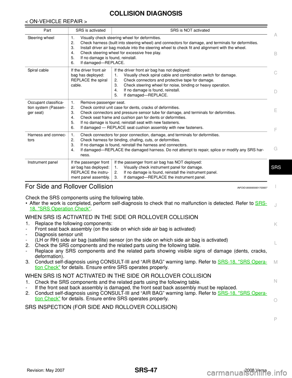
For Side and Rollover CollisionINFOID:0000000001703937
Check the SRS components using the following table.
• After the work is completed, perform self-diagnosis to check that no malfunction is detected. Refer to SRS-
18, "SRS Operation Check".
WHEN SRS IS ACTIVATED IN THE SIDE OR ROLLOVER COLLISION
1. Replace the following components:
- Front seat back assembly (on the side on which side air bag is activated)
- Diagnosis sensor unit
- (LH or RH) side air bag (satellite) sensor (on the side on which side air bag is activated)
2. Check the SRS components and the related parts using the following table.
- Replace any SRS components and the related parts showing visible signs of damage (dents, cracks,
deformation).
3. Conduct self-diagnosis using CONSULT-III and “AIR BAG” warning lamp. Refer to SRS-18, "
SRS Opera-
tion Check" for details. Ensure entire SRS operates properly.
WHEN SRS IS NOT ACTIVATED IN THE SIDE OR ROLLOVER COLLISION
1. Check the SRS components and the related parts using the following table.
- If the front seat back assembly is damaged, the front seat back assembly must be replaced.
2. Conduct self-diagnosis using CONSULT-III and “AIR BAG” warning lamp. Refer to SRS-18, "
SRS Opera-
tion Check" for details. Ensure entire SRS operates properly.
SRS INSPECTION (FOR SIDE AND ROLLOVER COLLISION)
Steering wheel 1. Visually check steering wheel for deformities.
2. Check harness (built into steering wheel) and connectors for damage, and terminals for deformities.
3. Install driver air bag module into the steering wheel to check fit and alignment with the wheel.
4. Check steering wheel for excessive free play.
5. If no damage is found, reinstall.
6. If damaged—REPLACE.
Spiral cable If the driver front air
bag has deployed:
REPLACE the spiral
cable.If the driver front air bag has not deployed:
1. Visually check spiral cable and combination switch for damage.
2. Check connectors and protective tape for damage.
3. Check steering wheel for noise, binding or heavy operation.
4. If no damage is found, reinstall.
5. If damaged—REPLACE.
Occupant classifica-
tion system (Passen-
ger seat)1. Remove passenger seat.
2. Check control unit case for dents, cracks of deformities.
3. Check connectors and pressure sensor tube for damage, and terminals for deformities.
4. Check seat frame and cushion pan for dents or deformities.
5. If no damage is found, reinstall seat with new fasteners.
6. If damaged — REPLACE seat cushion assembly with new fasteners.
Harness and connec-
tors1. Check connectors for poor connection, damage, and terminals for deformities.
2. Check harness for binding, chafing, cuts, or deformities.
3. If no damage is found, reinstall the harness and connectors.
4. If damaged—REPLACE the damaged harness. Do not attempt to repair, splice or modify any SRS har-
ness.
Instrument panel If the passenger front
air bag has deployed:
REPLACE the instru-
ment panel assembly.If the passenger front air bag has NOT deployed:
1. Visually check instrument panel for damage.
2. If no damage is found, reinstall the instrument panel.
3. If damaged—REPLACE the instrument panel. Part SRS is activated SRS is NOT activated
Page 2684 of 2771

STC-1
STEERING
C
D
E
F
H
I
J
K
L
M
SECTION STC
A
B
STC
N
O
P
CONTENTS
STEERING CONTROL SYSTEM
EPS
SERVICE INFORMATION ............................
2
PRECAUTIONS ...................................................2
Precaution for Supplemental Restraint System
(SRS) "AIR BAG" and "SEAT BELT PRE-TEN-
SIONER" ...................................................................
2
Precaution Necessary for Steering Wheel Rota-
tion After Battery Disconnect .....................................
2
Service Notice or Precaution for EPS System ..........2
EPS SYSTEM ......................................................4
System Description ...................................................4
Schematic .................................................................5
CAN Communication .................................................5
TROUBLE DIAGNOSIS ......................................6
Fail-Safe Function .....................................................6
How to Perform Trouble Diagnosis ...........................6
Component Parts Location ........................................7
Wiring Diagram - EPS - .............................................8
EPS Control Unit Input/Output Signal Reference
Value .........................................................................
9
EPS Terminal and Reference Value ........................10
CONSULT-III Function (EPS) ..................................11
Symptom Chart ........................................................13
TROUBLE DIAGNOSIS FOR SYSTEM ............14
DTC C1601 BATTERY VOLT ..................................14
DTC C1604 TORQUE SENSOR .............................15
DTC C1606 EPS MOTOR .......................................16
DTC C1607 EEPROM .............................................17
DTC C1608 CONTROL UNIT ..................................17
DTC C1609 CAN VHCL SPEED .............................18
DTC C1610 CAN ENG RPM ...................................19
DTC U1000 CAN COMM CIRCUIT .........................19
Component Inspection .............................................19
TROUBLE DIAGNOSIS FOR SYMPTOMS ......21
EPS Warning Lamp Does Not Turn ON ..................21
EPS Warning Lamp Does Not Turn OFF ................21
Steering Wheel Turning Force Is Heavy or Light .....22
Unbalance Steering Wheel Turning Force and Re-
turn Between Right and Left ....................................
23
Unbalance Steering Wheel Turning Force (Torque
Variation) .................................................................
24
Page 2685 of 2771
![NISSAN TIIDA 2008 Service Repair Manual STC-2
< SERVICE INFORMATION >[EPS]
PRECAUTIONS
SERVICE INFORMATION
PRECAUTIONS
Precaution for Supplemental Restraint System (SRS) "AIR BAG" and "SEAT BELT
PRE-TENSIONER"
INFOID:000000](/img/5/57399/w960_57399-2684.png "NISSAN TIIDA 2008 Service Repair Manual STC-2
< SERVICE INFORMATION >[EPS]
PRECAUTIONS
SERVICE INFORMATION
PRECAUTIONS
Precaution for Supplemental Restraint System (SRS) \"AIR BAG\" and \"SEAT BELT
PRE-TENSIONER\"
INFOID:000000")
STC-2
< SERVICE INFORMATION >[EPS]
PRECAUTIONS
SERVICE INFORMATION
PRECAUTIONS
Precaution for Supplemental Restraint System (SRS) "AIR BAG" and "SEAT BELT
PRE-TENSIONER"
INFOID:0000000001703869
The Supplemental Restraint System such as “AIR BAG” and “SEAT BELT PRE-TENSIONER”, used along
with a front seat belt, helps to reduce the risk or severity of injury to the driver and front passenger for certain
types of collision. This system includes seat belt switch inputs and dual stage front air bag modules. The SRS
system uses the seat belt switches to determine the front air bag deployment, and may only deploy one front
air bag, depending on the severity of a collision and whether the front occupants are belted or unbelted.
Information necessary to service the system safely is included in the SRS and SB section of this Service Man-
ual.
WARNING:
• To avoid rendering the SRS inoperative, which could increase the risk of personal injury or death in
the event of a collision which would result in air bag inflation, all maintenance must be performed by
an authorized NISSAN/INFINITI dealer.
• Improper maintenance, including incorrect removal and installation of the SRS, can lead to personal
injury caused by unintentional activation of the system. For removal of Spiral Cable and Air Bag
Module, see the SRS section.
• Do not use electrical test equipment on any circuit related to the SRS unless instructed to in this
Service Manual. SRS wiring harnesses can be identified by yellow and/or orange harnesses or har-
ness connectors.
Precaution Necessary for Steering Wheel Rotation After Battery Disconnect
INFOID:0000000001703870
NOTE:
• This Procedure is applied only to models with Intelligent Key system and NVIS/IVIS (NISSAN/INFINITI
VEHICLE IMMOBILIZER SYSTEM - NATS).
• Remove and install all control units after disconnecting both battery cables with the ignition knob in the
″LOCK″ position.
• Always use CONSULT-III to perform self-diagnosis as a part of each function inspection after finishing work.
If DTC is detected, perform trouble diagnosis according to self-diagnostic results.
For models equipped with the Intelligent Key system and NVIS/IVIS, an electrically controlled steering lock
mechanism is adopted on the key cylinder.
For this reason, if the battery is disconnected or if the battery is discharged, the steering wheel will lock and
steering wheel rotation will become impossible.
If steering wheel rotation is required when battery power is interrupted, follow the procedure below before
starting the repair operation.
OPERATION PROCEDURE
1. Connect both battery cables.
NOTE:
Supply power using jumper cables if battery is discharged.
2. Use the Intelligent Key or mechanical key to turn the ignition switch to the ″ACC″ position. At this time, the
steering lock will be released.
3. Disconnect both battery cables. The steering lock will remain released and the steering wheel can be
rotated.
4. Perform the necessary repair operation.
5. When the repair work is completed, return the ignition switch to the ″LOCK″ position before connecting
the battery cables. (At this time, the steering lock mechanism will engage.)
6. Perform a self-diagnosis check of all control units using CONSULT-III.
Service Notice or Precaution for EPS SystemINFOID:0000000001703871
CAUTION:
Check or confirm the following item when performing the trouble diagnosis.
Page 2686 of 2771
![NISSAN TIIDA 2008 Service Repair Manual PRECAUTIONS
STC-3
< SERVICE INFORMATION >[EPS]
C
D
E
F
H
I
J
K
L
MA
B
STC
N
O
P
• Check any possible causes by interviewing the symptom and it’s condition from the customer if any
malfunction, suc](/img/5/57399/w960_57399-2685.png "NISSAN TIIDA 2008 Service Repair Manual PRECAUTIONS
STC-3
< SERVICE INFORMATION >[EPS]
C
D
E
F
H
I
J
K
L
MA
B
STC
N
O
P
• Check any possible causes by interviewing the symptom and it’s condition from the customer if any
malfunction, suc")
PRECAUTIONS
STC-3
< SERVICE INFORMATION >[EPS]
C
D
E
F
H
I
J
K
L
MA
B
STC
N
O
P
• Check any possible causes by interviewing the symptom and it’s condition from the customer if any
malfunction, such as EPS warning lamp turns ON, occurs.
• Check if air pressure and size of tires are proper, the specified part is used for the steering wheel,
and control unit is genuine part.
• Check if the connection of steering column assembly and steering gear assembly is proper (there is
not looseness of mounting bolts, damage of rods, boots or sealants, and leakage of grease, etc).
• Check if the wheel alignment is adjusted properly.
• Check if there is any damage or modification to suspension or body resulting in increased weight or
altered ground clearance.
• Check if installation conditions of each link and suspension are proper.
• Check if the battery voltage is proper
• Check connection conditions of each connector are proper.
• Before connecting or disconnecting the EPS control unit har-
ness connector, turn ignition switch “OFF” and disconnect
battery ground cable. Because battery voltage is applied to
EPS control unit even if ignition switch is turned “OFF”.
• When connecting or disconnecting pin connectors into or
from EPS control unit, take care not to damage pin terminals
(bend or break).
When connecting pin connectors, make sure that there are no
bends or breaks on EPS control unit pin terminal.
• Before replacing EPS control unit, perform EPS control unit
input/output signal inspection and make sure whether EPS
control unit functions properly or not. Refer to STC-9, "
EPS
Control Unit Input/Output Signal Reference Value".
SEF289H
SEF291H
SDIA1848E
Page 2687 of 2771
![NISSAN TIIDA 2008 Service Repair Manual STC-4
< SERVICE INFORMATION >[EPS]
EPS SYSTEM
EPS SYSTEM
System DescriptionINFOID:0000000001703872
EPS CONTROL UNIT
• EPS control unit performs an arithmetical operation on data, such
as steering wh](/img/5/57399/w960_57399-2686.png "NISSAN TIIDA 2008 Service Repair Manual STC-4
< SERVICE INFORMATION >[EPS]
EPS SYSTEM
EPS SYSTEM
System DescriptionINFOID:0000000001703872
EPS CONTROL UNIT
• EPS control unit performs an arithmetical operation on data, such
as steering wh")
STC-4
< SERVICE INFORMATION >[EPS]
EPS SYSTEM
EPS SYSTEM
System DescriptionINFOID:0000000001703872
EPS CONTROL UNIT
• EPS control unit performs an arithmetical operation on data, such
as steering wheel turning force (sensor signal) from the torque
sensor, vehicle speed signal, etc. Then it generates an optimum
assist torque to the EPS motor according to the driving condition.
• EPS control unit decreases the output to EPS motor while
extremely using the power steering function (e.g., full steering) for
protecting EPS motor and EPS control unit (Protect overload sta-
tus). While activating protect overload status, the assist torque
gradually decreases, and the steering wheel turning force
becomes heavy. The normal assist torque reactivates by not steer-
ing.
• In case of an error in the electrical system, the fail-safe function
stops output signals to the EPS motor. Then the previous state is changed to the manual steering state.
• Self-diagnosis can be done with CONSULT-III.
EPS MOTOR
EPS motor provides the assist torque by control signal from EPS control unit.
TORQUE SENSOR
Torque sensor detects the steering torque, and transmit the signal to
EPS control unit.
REDUCTION GEAR
Reduction gear increases the assist torque provided from EPS motor with worm gears, and outputs to the col-
umn shaft.
EPS WARNING LAMP
Turns ON when there is a malfunction in EPS system. It indicates that fail-safe mode is engaged and enters a
manual steering state (Control turning force steering wheel becomes heavy).
Also turns ON when ignition switch is turned ON, for purpose of lamp check. Turns OFF after the engine starts
if system is normal.
EPS Warning Lamp Indication
SGIA1647E
SGIA1648E
Condition EPS warning lamp
Lamp checkTurns ON when ignition switch is turned ON.
Turns OFF after engine start.
EPS system malfunctionON
Other than above (system normal) OFF
Page 2688 of 2771
![NISSAN TIIDA 2008 Service Repair Manual EPS SYSTEM
STC-5
< SERVICE INFORMATION >[EPS]
C
D
E
F
H
I
J
K
L
MA
B
STC
N
O
P
SchematicINFOID:0000000001703873
COMPONENTS FUNCTION DESCRIPTION
CAN CommunicationINFOID:0000000001703874
SYSTEM DESCRIPT](/img/5/57399/w960_57399-2687.png "NISSAN TIIDA 2008 Service Repair Manual EPS SYSTEM
STC-5
< SERVICE INFORMATION >[EPS]
C
D
E
F
H
I
J
K
L
MA
B
STC
N
O
P
SchematicINFOID:0000000001703873
COMPONENTS FUNCTION DESCRIPTION
CAN CommunicationINFOID:0000000001703874
SYSTEM DESCRIPT")
EPS SYSTEM
STC-5
< SERVICE INFORMATION >[EPS]
C
D
E
F
H
I
J
K
L
MA
B
STC
N
O
P
SchematicINFOID:0000000001703873
COMPONENTS FUNCTION DESCRIPTION
CAN CommunicationINFOID:0000000001703874
SYSTEM DESCRIPTION
CAN (Controller Area Network) is a serial communication line for real time application. It is an on-vehicle mul-
tiplex communication line with high data communication speed and excellent error detection ability. Many elec-
tronic control units are equipped onto a vehicle, and each control unit shares information and links with other
control units during operation (not independent). In CAN communication, control units are connected with 2
communication lines (CAN-H line, CAN-L line) allowing a high rate of information transmission with less wiring.
Each control unit transmits/receives data but selectively reads required data only.
For details, refer to LAN-23, "
CAN System Specification Chart".
WGIA0187E
Component parts Function
EPS control unit
(Electric power steering control unit)• Outputs optimum assist torque signal to EPS motor.
• Reduces output signals to EPS motor and protects EPS motor and EPS control unit when us-
ing power steering continuously and excessively.
• As a fail-safe function, turned off output signal to EPS motor and then enters a manual steer-
ing state, if malfunction is detected in EPS system.
EPS motor Products assist torque by control signal from EPS control unit.
Torque sensor Detects steering wheel turning force and outputs sensor signal to EPS control unit.
Reduction gear Increases motor-produced assist torque by worm gear and transmits it to column shaft.
EPS warning lamp Illuminates if malfunction is detected in electrical system of EPS system.
ECMTransmits the following signals via CAN communication to EPS control unit.
• Engine status signal
ABS actuator and electric unit (con-
trol unit) (With ABS)Transmits the following signals via CAN communication to EPS control unit.
• Vehicle speed signal
Combination meterTransmits the following signals via CAN communication to EPS control unit.
• Vehicle speed signal
TCM (Without ABS)Transmits the following signals via CAN communication to EPS control unit.
• Vehicle speed signal
Page 2689 of 2771
![NISSAN TIIDA 2008 Service Repair Manual STC-6
< SERVICE INFORMATION >[EPS]
TROUBLE DIAGNOSIS
TROUBLE DIAGNOSIS
Fail-Safe FunctionINFOID:0000000001703875
• If any malfunction occurs in the system, and control unit detects the malfunction,](/img/5/57399/w960_57399-2688.png "NISSAN TIIDA 2008 Service Repair Manual STC-6
< SERVICE INFORMATION >[EPS]
TROUBLE DIAGNOSIS
TROUBLE DIAGNOSIS
Fail-Safe FunctionINFOID:0000000001703875
• If any malfunction occurs in the system, and control unit detects the malfunction,")
STC-6
< SERVICE INFORMATION >[EPS]
TROUBLE DIAGNOSIS
TROUBLE DIAGNOSIS
Fail-Safe FunctionINFOID:0000000001703875
• If any malfunction occurs in the system, and control unit detects the malfunction, EPS warning lamp on com-
bination meter turns ON to indicate system malfunction.
• When EPS warning lamp is ON, enters a manual steering state. (Control turning force steering wheel
becomes heavy.)
How to Perform Trouble DiagnosisINFOID:0000000001703876
BASIC CONCEPT
• To perform trouble diagnosis, it is a must to have an understanding about vehicle systems (control and
mechanism) thoroughly.
• It is also important to clarify customer complaints before starting
the inspection.
First of all, reproduce the symptoms, and understand them fully.
Ask customer about his/her complaints carefully. In some cases, it
will be necessary to check symptoms by driving vehicle with cus-
tomer.
CAUTION:
Customers are not professionals. It is dangerous to make an
easy guess like “maybe the customer means that...” or
“maybe the customer mentions this symptom”.
• It is essential to check symptoms right from the beginning in order
to repair malfunctions completely.
For intermittent malfunctions, reproduce symptoms based on inter-
view with customer and past examples. Do not perform inspection
on ad hoc basis. Most intermittent malfunctions are caused by
poor contacts. In this case, it will be effective to shake suspected
harness or connector by hand. When repairing without any symp-
tom diagnosis, you cannot judge if malfunctions has actually been
eliminated.
PRECAUTIONS FOR TROUBLE DIAGNOSIS
• Be sure to check the procedures of the trouble diagnosis in advance. Refer to "How to Perform Trouble
Diagnosis" .
• Always erase memory after completing trouble diagnosis. Refer to STC-11, "
CONSULT-III Function (EPS)" .
• Checking continuity and voltage between units, be sure to check connector terminals for disconnection,
looseness, bend, or collapse. Repair or replace applicable part if any non-standard condition is detected.
• Be careful not to forcibly extend any connector terminal if a circuit tester is used for the check.
• Always confirm the general precautions. Refer to GI-3, "
General Precaution" .
INTERVIEW
• Complaints vary depending on the person. It is important to clarify
the customer's actual remarks.
• Ask the customer about what symptoms occur under what condi-
tions. Use the information to reproduce the symptom of confirm by
vehicle.
SEF233G
SEF234G
SEF907L
Page 2693 of 2771
![NISSAN TIIDA 2008 Service Repair Manual STC-10
< SERVICE INFORMATION >[EPS]
TROUBLE DIAGNOSIS
*1 : In the front of the value, “L” is displayed at steering left and “R” is displayed at steering right.
*2 : Almost in accordance with t](/img/5/57399/w960_57399-2692.png "NISSAN TIIDA 2008 Service Repair Manual STC-10
< SERVICE INFORMATION >[EPS]
TROUBLE DIAGNOSIS
*1 : In the front of the value, “L” is displayed at steering left and “R” is displayed at steering right.
*2 : Almost in accordance with t")
STC-10
< SERVICE INFORMATION >[EPS]
TROUBLE DIAGNOSIS
*1 : In the front of the value, “L” is displayed at steering left and “R” is displayed at steering right.
*2 : Almost in accordance with the value of “MOTOR SIG”. It is not a malfunction though these values are not accorded when steering
quickly.
*3 : It is not a malfunction, though it might not be corresponding just after ignition switch is turned ON.
*4 : It turns to OFF after waiting for a short period of time.
EPS Terminal and Reference ValueINFOID:0000000001703880
EPS HARNESS CONNECTOR TERMINAL LAYOUT
TERMINALS AND REFERENCE VALUES FOR EPS CONTROL UNIT
Monitor item (Unit) Content Condition Display value
MOTOR VOL (V)Power supply voltage for
EPS control unitIgnition switch: ON Battery voltage
TORQUE SENSOR (Nm)Steering wheel turning
forceEngine runningSteering wheel: Not
steering (There is no
steering force) 0.00 Nm
Steering wheel: Steer-
ing0 – 8.19 Nm
*1 (The value
is changed according to
steering left or right)
MOTOR SIG (A)Command current to EPS
motorEngine runningSteering wheel: Not
steering (There is no
steering force)0.00 A
Steering wheel: Steer-
ing0 – 65.00 A (The value is
changed according to
steering left or right)
MOTOR CURRENT (A)Consumption current of
EPS motorEngine runningSteering wheel: Not
steering (There is no
steering force)0.00 A
Steering wheel: Steer-
ing0 – 65.00 A
*2 (The value
is changed according to
steering left or right)
VEHICLE SPEED (km/h) or (mph) Vehicle speedVehicle stopped 0 km/h (0 mph)
While drivingApproximately equal to
the indication on speed-
ometer (Inside of ±10%)
*3
WARNING LAMP (ON/OFF)EPS warning lamp condi-
tionEPS warning lamp: ON ON
EPS warning lamp: OFF OFF
DERATING STAT (ON/OFF) Protect overload status Engine runningSteering wheel: Nor-
mal steeringOFF
Steering wheel: Steer-
ing over the stopON
*4
ENGINE STATUS (RUN/STOP) Engine statusEngine stopped
(Engine speed: Less than 400 rpm)STOP
Engine running
(Engine speed: 400 rpm or more)RUN
SGIA1624E
Page 2694 of 2771
![NISSAN TIIDA 2008 Service Repair Manual TROUBLE DIAGNOSIS
STC-11
< SERVICE INFORMATION >[EPS]
C
D
E
F
H
I
J
K
L
MA
B
STC
N
O
P
Data are reference values and are measured between each terminal and ground.
CAUTION:
When using a circuit tester](/img/5/57399/w960_57399-2693.png "NISSAN TIIDA 2008 Service Repair Manual TROUBLE DIAGNOSIS
STC-11
< SERVICE INFORMATION >[EPS]
C
D
E
F
H
I
J
K
L
MA
B
STC
N
O
P
Data are reference values and are measured between each terminal and ground.
CAUTION:
When using a circuit tester")
TROUBLE DIAGNOSIS
STC-11
< SERVICE INFORMATION >[EPS]
C
D
E
F
H
I
J
K
L
MA
B
STC
N
O
P
Data are reference values and are measured between each terminal and ground.
CAUTION:
When using a circuit tester to measure voltage for inspection, be sure not to extend forcibly any connector terminals.
CONSULT-III Function (EPS)INFOID:0000000001703881
FUNCTION
CONSULT-III can display each diagnostic item using the diagnostic test modes shown following.
SELF-DIAG RESULTS MODE
Display Item List
Te r m i n a lWire
colorItem Condition Data (Approx.)
4 V Torque sensor sub Engine runningSteering wheel: Not steering
(There in no steering force)2.5 V
Steering wheel: Steering1.7 V – 3.3 V
(The value is changed accord-
ing to steering left or right)
5 BR Torque sensor power supplyIgnition switch: ON 8 V
Ignition switch: OFF 0 V
6 G Torque sensor main Engine runningSteering wheel: Not steering
(There is no steering force)2.5 V
Steering wheel: Steering1.7 V – 3.3 V
(The value is changed accord-
ing to steering left or right)
7 R Torque sensor ground Always 0 V
9 L CAN-H — —
10 O Power supplyIgnition switch: ON Battery voltage
Ignition switch: OFF 0 V
16 P CAN-L — —
17 R Power supply (Memory back-up)Ignition switch: ON Battery voltage
Ignition switch: OFF Battery voltage
18 B Ground Always 0 V
19 — Motor (+) — —
20 — Motor (–) — —
Diagnostic test mode Function Reference page
Self-diagnostic results • Self-diagnostic results can be read and erased quickly."SELF-DIAG
RESULTS
MODE"
Data monitor • Input/Output data in the EPS control unit can be read."DATA MONI-
TOR"
CAN diagnostic support monitor • The results of transmit/receive diagnosis of CAN communication can be read.LAN-6
ECU part number • EPS control unit part number can be read."EPS CON-
TROL UNIT
PART NUM-
BER"
Page 2695 of 2771
![NISSAN TIIDA 2008 Service Repair Manual STC-12
< SERVICE INFORMATION >[EPS]
TROUBLE DIAGNOSIS
CAUTION:
If “CAN COMM CIRCUIT [U1000]” is displayed with other DTCs, first perform the trouble diagnosis for CAN communication
line.
How to Er](/img/5/57399/w960_57399-2694.png "NISSAN TIIDA 2008 Service Repair Manual STC-12
< SERVICE INFORMATION >[EPS]
TROUBLE DIAGNOSIS
CAUTION:
If “CAN COMM CIRCUIT [U1000]” is displayed with other DTCs, first perform the trouble diagnosis for CAN communication
line.
How to Er")
STC-12
< SERVICE INFORMATION >[EPS]
TROUBLE DIAGNOSIS
CAUTION:
If “CAN COMM CIRCUIT [U1000]” is displayed with other DTCs, first perform the trouble diagnosis for CAN communication
line.
How to Erase Self-Diagnostic Results
1. Perform applicable inspection of malfunctioning item and then repair or replace.
2. Turn ignition switch “OFF” to erase memory.
3. Turn ignition switch “ON” and select “SELF-DIAG RESULTS” mode with CONSULT-III.
4. Touch “ERASE” on CONSULT-III screen to erase DTC memory.
CAUTION:
If memory cannot be erased, perform diagnosis.
DATA MONITOR
Display Item List
EPS CONTROL UNIT PART NUMBER
Display a part number of EPS control unit carried by a vehicle.
Item
(CONSULT-III screen terms)Diagnostic item is detected when.... Check item
BATTERY VOLT
[C1601]When the power supply malfunction supplied to EPS control unit is
detected.STC-14, "
DTC C1601
BATTERY VOLT"
TORQUE SENSOR
[C1604]When the torque sensor malfunction assembled in steering column
assembly is detected. STC-15, "DTC C1604
TORQUE SENSOR"
EPS MOTOR
[C1606]When the motor driver malfunction of EPS control unit or EPS motor
malfunction is detected.STC-16, "DTC C1606
EPS MOTOR"
EEPROM
[C1607]When the memory (EEPROM) system malfunction is detected in
EPS control unit.STC-17, "DTC C1607
EEPROM"
CONTROL UNIT
[C1608]When the internal malfunction is detected in EPS control unit.STC-17, "DTC C1608
CONTROL UNIT"
CAN VHCL SPEED
[C1609]When the malfunction is detected in vehicle speed signal received
with CAN communication.STC-18, "DTC C1609
CAN VHCL SPEED"
CAN ENG RPM
[C1610]When the malfunction is detected in engine status signal received
with CAN communication.STC-19, "DTC C1610
CAN ENG RPM"
CAN COMM CIRCUIT
[U1000]When EPS control unit is not transmitting or receiving CAN commu-
nication signal 2 seconds or more.STC-19, "DTC U1000
CAN COMM CIRCUIT"
NO DTC IS DETECTED.
FURTHER TESTING MAY BE RE-
QUIRED.No NG item has been detected. —
Monitor item (Unit) Remarks
MOTOR VOL (V) Power supply voltage for EPS control unit is displayed
TORQUE SENSOR (Nm) Steering wheel turning force detected by torque sensor is displayed
MOTOR SIG (A) Current commanded value to EPS motor is displayed
MOTOR CURRENT (A) Current value consumed by EPS motor is displayed
VEHICLE SPEED (km/h) or (mph) Vehicle speed is displayed from vehicle speed signal with CAN communication
WARNING LAMP (ON/OFF) EPS warning lamp control status is displayed
DERATING STAT (ON/OFF) Protect overload status is displayed
ENGINE STATUS (STOP/RUN) Engine speed is displayed from engine status signal with CAN communication