Engine oil NISSAN TIIDA 2008 Service User Guide
[x] Cancel search | Manufacturer: NISSAN, Model Year: 2008, Model line: TIIDA, Model: NISSAN TIIDA 2008Pages: 2771, PDF Size: 60.61 MB
Page 60 of 2771
AT-48
< SERVICE INFORMATION >
TROUBLE DIAGNOSIS
Inspections Before Trouble Diagnosis
INFOID:0000000001703182
A/T FLUID CHECK
Fluid Leakage and Fluid Level Check
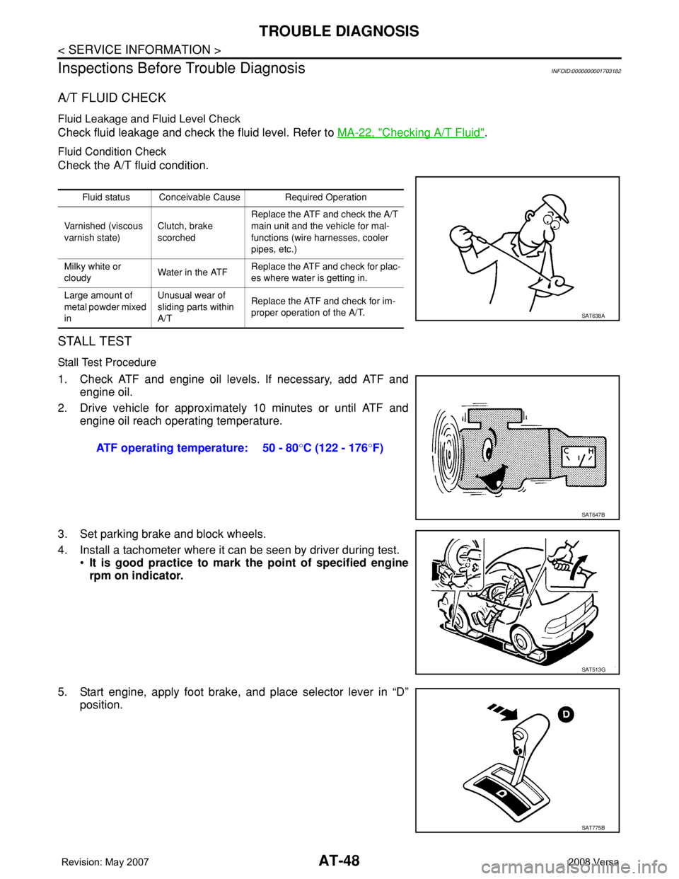
Check fluid leakage and check the fluid level. Refer to MA-22, "Checking A/T Fluid".
Fluid Condition Check
Check the A/T fluid condition.
STALL TEST
Stall Test Procedure
1. Check ATF and engine oil levels. If necessary, add ATF and
engine oil.
2. Drive vehicle for approximately 10 minutes or until ATF and
engine oil reach operating temperature.
3. Set parking brake and block wheels.
4. Install a tachometer where it can be seen by driver during test.
•It is good practice to mark the point of specified engine
rpm on indicator.
5. Start engine, apply foot brake, and place selector lever in “D”
position.
Fluid status Conceivable Cause Required Operation
Varnished (viscous
varnish state)Clutch, brake
scorchedReplace the ATF and check the A/T
main unit and the vehicle for mal-
functions (wire harnesses, cooler
pipes, etc.)
Milky white or
cloudyWater in the ATFReplace the ATF and check for plac-
es where water is getting in.
Large amount of
metal powder mixed
inUnusual wear of
sliding parts within
A/TReplace the ATF and check for im-
proper operation of the A/T.
SAT638A
ATF operating temperature: 50 - 80°C (122 - 176°F)
SAT647B
SAT513G
SAT775B
Page 63 of 2771
TROUBLE DIAGNOSIS
AT-51
< SERVICE INFORMATION >
D
E
F
G
H
I
J
K
L
MA
B
AT
N
O
P
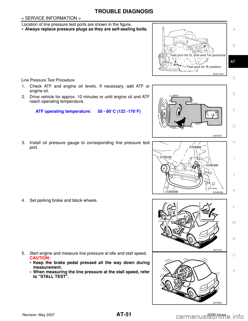
Location of line pressure test ports are shown in the figure.
•Always replace pressure plugs as they are self-sealing bolts.
Line Pressure Test Procedure
1. Check ATF and engine oil levels. If necessary, add ATF or
engine oil.
2. Drive vehicle for approx. 10 minutes or until engine oil and ATF
reach operating temperature.
3. Install oil pressure gauge to corresponding line pressure test
port.
4. Set parking brake and block wheels.
5. Start engine and measure line pressure at idle and stall speed.
CAUTION:
• Keep the brake pedal pressed all the way down during
measurement.
• When measuring the line pressure at the stall speed, refer
to "STALL TEST".
SCIA7187E
ATF operating temperature: 50 - 80°C (122 -176°F)
SAT647B
SCIA6528J
SAT513G
SAT493G
Page 64 of 2771
AT-52
< SERVICE INFORMATION >
TROUBLE DIAGNOSIS
Line Pressure
Judgement of Line Pressure Test
Road TestINFOID:0000000001703183
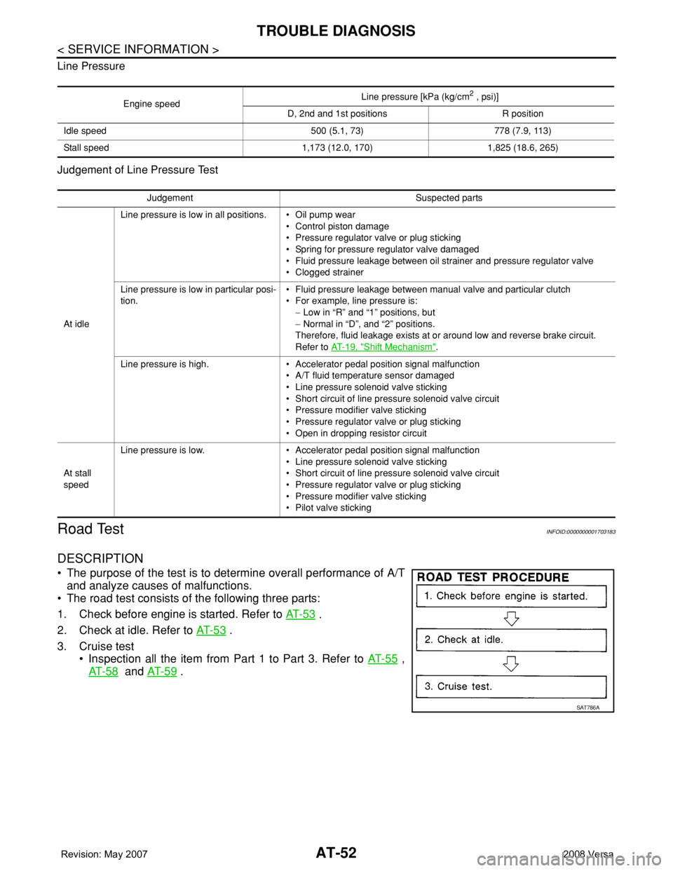
DESCRIPTION
• The purpose of the test is to determine overall performance of A/T
and analyze causes of malfunctions.
• The road test consists of the following three parts:
1. Check before engine is started. Refer to AT- 5 3
.
2. Check at idle. Refer to AT- 5 3
.
3. Cruise test
• Inspection all the item from Part 1 to Part 3. Refer to AT- 5 5
,
AT- 5 8
and AT- 5 9 .
Engine speedLine pressure [kPa (kg/cm
2 , psi)]
D, 2nd and 1st positions R position
Idle speed 500 (5.1, 73) 778 (7.9, 113)
Stall speed 1,173 (12.0, 170) 1,825 (18.6, 265)
Judgement Suspected parts
At idleLine pressure is low in all positions. • Oil pump wear
• Control piston damage
• Pressure regulator valve or plug sticking
• Spring for pressure regulator valve damaged
• Fluid pressure leakage between oil strainer and pressure regulator valve
• Clogged strainer
Line pressure is low in particular posi-
tion.• Fluid pressure leakage between manual valve and particular clutch
• For example, line pressure is:
− Low in “R” and “1” positions, but
− Normal in “D”, and “2” positions.
Therefore, fluid leakage exists at or around low and reverse brake circuit.
Refer to AT- 1 9 , "
Shift Mechanism".
Line pressure is high. • Accelerator pedal position signal malfunction
• A/T fluid temperature sensor damaged
• Line pressure solenoid valve sticking
• Short circuit of line pressure solenoid valve circuit
• Pressure modifier valve sticking
• Pressure regulator valve or plug sticking
• Open in dropping resistor circuit
At stall
speedLine pressure is low. • Accelerator pedal position signal malfunction
• Line pressure solenoid valve sticking
• Short circuit of line pressure solenoid valve circuit
• Pressure regulator valve or plug sticking
• Pressure modifier valve sticking
• Pilot valve sticking
SAT786A
Page 67 of 2771

TROUBLE DIAGNOSIS
AT-55
< SERVICE INFORMATION >
D
E
F
G
H
I
J
K
L
MA
B
AT
N
O
P
1. Apply foot brake.
2. Move selector lever to “R” position.
Is there large shock when changing from
“N” to “R” position?
YES >> • Mark the box on the AT-40, "How to Perform Trouble
Diagnosis for Quick and Accurate Repair" .
•Go to AT-180, "
Large Shock "N" → "R" Position" .
• Continue “Road Test”.
NO >> GO TO 6.
6.CHECK VEHICLE MOVE
Release foot brake for several seconds.
Does vehicle creep backward when foot brake is released?
YES >> GO TO 7.
NO >> • Mark the box on the AT-40, "
How to Perform Trouble
Diagnosis for Quick and Accurate Repair" .
•Go to AT-181, "
Vehicle Does Not Creep Backward in
"R" Position" .
• Continue “Road Test”.
7.CHECK VEHICLE MOVE
Move selector lever to “D”, “2” and “1” positions and check if vehicle
creeps forward.
Does vehicle creep forward in all three positions?
YES >> Go to AT-55, "Cruise Test - Part 1" .
NO >> • Mark the box on the AT-40, "
How to Perform Trouble
Diagnosis for Quick and Accurate Repair" .
•Go to AT-182, "
Vehicle Does Not Creep Forward in
"D", "2" or "1" Position" .
• Continue “Road Test”.
Cruise Test - Part 1INFOID:0000000001703186
1.CHECK STARTING GEAR (D1 ) POSITION
1. Drive vehicle for approximately 10 minutes to warm engine oil and ATF up to operating temperature.
2. Park vehicle on flat surface.
SAT797A
SAT772B
SAT799A
SAT773B
ATF operating temperature: 50 - 80°C (122 - 176°F)
Page 80 of 2771

AT-68
< SERVICE INFORMATION >
TROUBLE DIAGNOSIS
Slips/Will Not EngageRaces extremely fast
or slips in changing
from D
3 to D2 when
depressing accelera-
tor pedal. ON vehicle1. A/T fluid levelMA-22
2. Accelerator pedal position sensor EC-493
3. Line pressure testAT- 4 8
4. Line pressure solenoid valveAT- 1 2 9
5. Shift solenoid valve BAT- 1 3 9
6. Control valve assemblyAT- 2 1 6
OFF vehicle7. Brake bandAT- 3 0 78. High clutchAT- 2 8 4
Races extremely fast
or slips in changing
from D
4 or D3 to D 1
when depressing ac-
celerator pedal.ON vehicle1. A/T fluid levelMA-22
2. Accelerator pedal position sensorEC-493
3. Line pressure testAT- 4 8
4. Line pressure solenoid valveAT- 1 2 9
5. Shift solenoid valve AAT- 1 3 4
6. Shift solenoid valve BAT- 1 3 9
7. Control valve assemblyAT- 2 1 6
OFF vehicle8. Forward clutchAT- 2 8 89. Forward one-way clutchAT- 2 9 9
10. Low one-way clutchAT- 2 4 0
Vehicle will not run in
any position.ON vehicle1. A/T fluid levelMA-22
2. Control cable adjustmentAT- 2 0 7
3. Line pressure testAT- 4 8
4. Line pressure solenoid valveAT- 1 2 9
OFF vehicle5. Oil pumpAT- 2 6 0
6. High clutchAT- 2 8 4
7. Brake bandAT- 3 0 7
8. Low & reverse brakeAT- 2 9 5
9. Torque converterAT- 2 4 0
10. Parking componentsAT- 2 3 0
OthersEngine cannot be
started in “P” and “N”
positions.
AT- 1 7 8
ON vehicle1. Ignition switch and starterPG-3
, SC-8
2. Control cable adjustmentAT- 2 0 7
3. PNP switch adjustmentAT- 2 1 9
Engine starts in posi-
tions other than “P”
and “N”.ON vehicle1. Control cable adjustmentAT- 2 0 7
2. PNP switch adjustmentAT- 2 1 9
Transaxle noise in“ P”
and “N” positions.ON vehicle1. A/T fluid levelMA-22
2. Line pressure testAT- 4 8
3. Accelerator pedal position sensorEC-493
4. Vehicle speed sensor·A/T (Revolution sensor)
and vehicle speed sensor·MTRAT- 9 6, AT- 1 4 9
OFF vehicle5. Oil pumpAT- 2 6 06. Torque converterAT- 2 4 0
Items Symptom Condition Diagnostic item Reference page
Page 82 of 2771

AT-70
< SERVICE INFORMATION >
TROUBLE DIAGNOSIS
OthersMaximum speed not
attained. Poor accel-
eration.ON vehicle1. A/T fluid levelMA-22
2. PNP switch adjustmentAT- 2 1 9
3. Overdrive control switchAT- 1 6 7
4. Accelerator pedal position sensorEC-493
5. Vehicle speed sensor·A/T (Revolution sensor)
and vehicle speed sensor·MTRAT- 9 6, AT- 1 4 9
6. Shift solenoid valve AAT- 1 3 4
7. Shift solenoid valve BAT- 1 3 9
8. Control valve assemblyAT- 2 1 6
OFF vehicle9. Reverse clutchAT- 2 7 9
10. High clutchAT- 2 8 4
11. Brake bandAT- 3 0 7
12. Low & reverse brakeAT- 2 9 5
13. Oil pumpAT- 2 6 0
14. Torque converterAT- 2 4 0
Transaxle noise in
“D”, “2”, “1” and “R”
positions.ON vehicle 1. A/T fluid levelMA-22
OFF vehicle 2. Torque converterAT- 2 4 0
Engine brake does
not operate in “1” po-
sition.ON vehicle1. PNP switch adjustmentAT- 2 1 9
2. Control cable adjustmentAT- 2 0 7
3. Vehicle speed sensor·A/T (Revolution sensor)
and vehicle speed sensor·MTRAT- 9 6, AT- 1 4 9
4. Control valve assemblyAT- 2 1 6
5. Overrun clutch solenoid valveAT- 1 4 4
OFF vehicle6. Overrun clutchAT- 2 8 87. Low & reverse brakeAT- 2 9 5
Transaxle overheats.ON vehicle1. A/T fluid levelMA-22
2. Engine idling speedEC-73
3. Accelerator pedal position sensorEC-493
4. Line pressure testAT- 4 8
5. Line pressure solenoid valveAT- 1 2 9
6. Control valve assemblyAT- 2 1 6
OFF vehicle7. Oil pumpAT- 2 6 0
8. Reverse clutchAT- 2 7 9
9. High clutchAT- 2 8 4
10. Brake bandAT- 3 0 7
11. Forward clutchAT- 2 8 8
12. Overrun clutchAT- 2 8 8
13. Low & reverse brakeAT- 2 9 5
14. Torque converterAT- 2 4 0
Items Symptom Condition Diagnostic item Reference page
Page 83 of 2771
TROUBLE DIAGNOSIS
AT-71
< SERVICE INFORMATION >
D
E
F
G
H
I
J
K
L
MA
B
AT
N
O
P
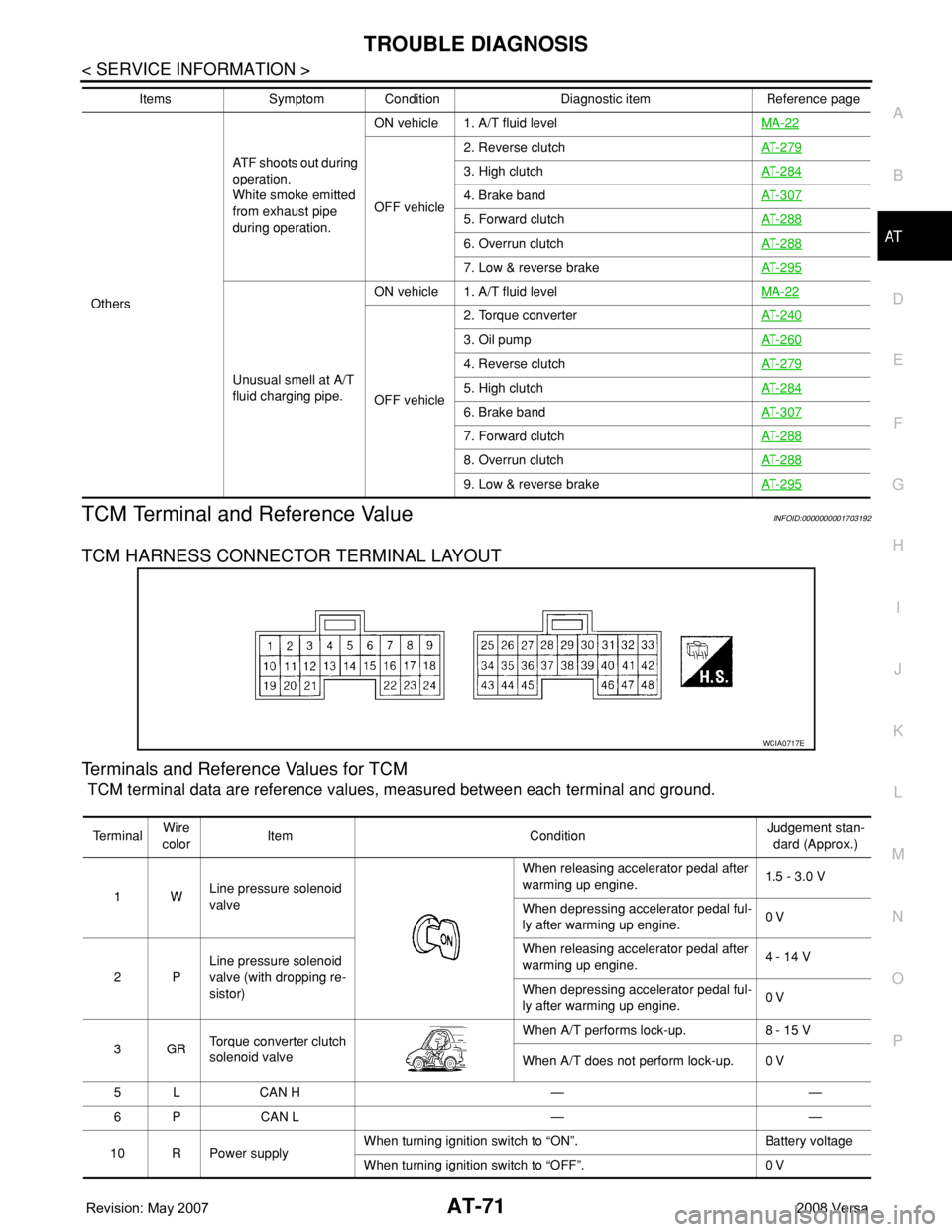
TCM Terminal and Reference ValueINFOID:0000000001703192
TCM HARNESS CONNECTOR TERMINAL LAYOUT
Terminals and Reference Values for TCM
TCM terminal data are reference values, measured between each terminal and ground.
OthersATF shoots out during
operation.
White smoke emitted
from exhaust pipe
during operation.ON vehicle 1. A/T fluid levelMA-22
OFF vehicle2. Reverse clutchAT- 2 7 9
3. High clutchAT- 2 8 4
4. Brake bandAT- 3 0 7
5. Forward clutchAT- 2 8 8
6. Overrun clutchAT- 2 8 8
7. Low & reverse brakeAT- 2 9 5
Unusual smell at A/T
fluid charging pipe.ON vehicle 1. A/T fluid levelMA-22
OFF vehicle2. Torque converterAT- 2 4 0
3. Oil pumpAT- 2 6 0
4. Reverse clutchAT- 2 7 9
5. High clutchAT- 2 8 4
6. Brake bandAT- 3 0 7
7. Forward clutchAT- 2 8 8
8. Overrun clutchAT- 2 8 8
9. Low & reverse brakeAT- 2 9 5
Items Symptom Condition Diagnostic item Reference page
WCIA0717E
Te r m i n a lWire
colorItem ConditionJudgement stan-
dard (Approx.)
1WLine pressure solenoid
valveWhen releasing accelerator pedal after
warming up engine.1.5 - 3.0 V
When depressing accelerator pedal ful-
ly after warming up engine.0 V
2PLine pressure solenoid
valve (with dropping re-
sistor)When releasing accelerator pedal after
warming up engine.4 - 14 V
When depressing accelerator pedal ful-
ly after warming up engine.0 V
3GRTorque converter clutch
solenoid valveWhen A/T performs lock-up. 8 - 15 V
When A/T does not perform lock-up. 0 V
5 L CAN H — —
6 P CAN L — —
10 R Power supplyWhen turning ignition switch to “ON”. Battery voltage
When turning ignition switch to “OFF”. 0 V
Page 106 of 2771

AT-94
< SERVICE INFORMATION >
DTC P0710 A/T FLUID TEMPERATURE SENSOR CIRCUIT
3. Check continuity between terminal cord assembly harness con-
nector terminal and TCM connector terminal.
4. If OK, check harness for short to ground and short to power.
5. If OK, check continuity between ground and transaxle assembly.
6. Reinstall any part removed.
OK or NG
OK >> GO TO 5.
NG >> Repair open circuit or short to ground or short to power in harness or connectors.
5.CHECK A/T FLUID TEMPERATURE SENSOR WITH TERMINAL CORD ASSEMBLY
1. Turn ignition switch OFF.
2. Disconnect terminal cord assembly harness connector in engine room.
3. Check resistance between terminal cord assembly harness con-
nector terminals.
4. Reinstall any part removed.
OK or NG
OK >> GO TO 6.
NG >> Repair or replace damaged parts.
6.DETECT MALFUNCTIONING ITEM
1. Remove oil pan. Refer to AT-216, "
Control Valve Assembly and Accumulators".
2. Check the following.
- A/T fluid temperature sensor
• Check resistance between terminal cord assembly harness con-
nector terminals while changing temperature as shown.
- Harness of terminal cord assembly for short or open
OK or NG
OK >> GO TO 7.
NG >> Repair or replace damaged parts.
7.CHECK DTC
Perform AT-91, "
DTC Confirmation Procedure".
OK or NG
Item Connector Terminal Continuity
TCM E32 42
Ye s
Terminal cord assembly
harness connectorF30 7
TCM E32 47
Ye s
Terminal cord assembly
harness connectorF30 6
SCIA2660E
Item Connector Terminal Temperature
[°C (°F)]Resistance
(Approx.)
A/T fluid tem-
perature sensorF30 6 - 720 (68) 2.5 kΩ
80 (176) 0.3 kΩ
SCIA4948E
Item Connector Terminal Temperature
[°C (°F)]Resistance
(Approx.)
A/T fluid tem-
perature sensorF30 6 - 720 (68) 2.5 kΩ
80 (176) 0.3 kΩ
SCIA7831E
Page 126 of 2771
AT-114
< SERVICE INFORMATION >
DTC P0734 A/T 4TH GEAR FUNCTION
DTC P0734 A/T 4TH GEAR FUNCTION
DescriptionINFOID:0000000001703246
• This malfunction will not be detected while the OD OFF indicator lamp is indicating another self-diagnosis
malfunction.
• This malfunction is detected when the A/T does not shift into fourth gear position or the torque converter
clutch does not lock up as instructed by the TCM. This is not caused by electrical malfunction (circuits open
or shorted) but by mechanical malfunction such as control valve sticking, improper solenoid valve operation,
malfunctioning oil pump or torque converter clutch, etc.
CONSULT-III Reference Value in Data Monitor ModeINFOID:0000000001703247
Remarks: Specification data are reference values.
On Board Diagnosis LogicINFOID:0000000001703248
• This is an OBD-II self-diagnostic item.
• Diagnostic trouble code “P0734 A/T 4TH GR FNCTN” with CONSULT-III is detected when A/T cannot be
shifted to the 4th gear position even if electrical circuit is good.
• This diagnosis monitors actual gear position by checking the torque converter slip ratio calculated by TCM
as follows:
Torque converter slip ratio = A x C/B
A: Output shaft revolution signal from revolution sensor
B: Engine speed signal from ECM
C: Gear ratio determined as gear position which TCM supposes
If the actual gear position is much lower than the position (4th) supposed by TCM, the slip ratio will be much
less than normal. In case the ratio does not reach the specified value, TCM judges this diagnosis malfunc-
tion.
This malfunction will be caused when shift solenoid valve A is stuck open or shift solenoid valve B is stuck
closed.
• Gear positions supposed by TCM are as follows.
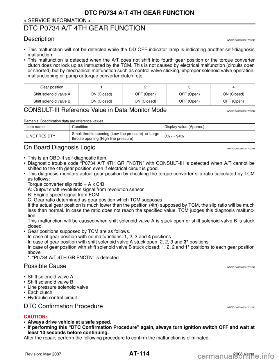
In case of gear position with no malfunctions: 1, 2, 3 and 4 positions
In case of gear position with shift solenoid valve A stuck open: 2, 2, 3 and 3* positions
In case of gear position with shift solenoid valve B stuck closed: 1, 2, 2 and 1* positions to each gear position
above
*: “P0734 A/T 4TH GR FNCTN” is detected.
Possible CauseINFOID:0000000001703249
• Shift solenoid valve A
• Shift solenoid valve B
• Line pressure solenoid valve
• Each clutch
• Hydraulic control circuit
DTC Confirmation ProcedureINFOID:0000000001703250
CAUTION:
• Always drive vehicle at a safe speed.
• If performing this “DTC Confirmation Procedure” again, always turn ignition switch OFF and wait at
least 10 seconds before continuing.
After the repair, perform the following procedure to confirm the malfunction is eliminated.
Gear position 1 2 3 4
Shift solenoid valve A ON (Closed) OFF (Open) OFF (Open) ON (Closed)
Shift solenoid valve B ON (Closed) ON (Closed) OFF (Open) OFF (Open)
Item name Condition Display value (Approx.)
LINE PRES DTYSmall throttle opening (Low line pressure) ⇔ Large
throttle opening (High line pressure)0% ⇔ 94%
Page 136 of 2771
AT-124
< SERVICE INFORMATION >
DTC P0744 A/T TCC S/V FUNCTION (LOCK-UP)
DTC P0744 A/T TCC S/V FUNCTION (LOCK-UP)
DescriptionINFOID:0000000001703260
• This malfunction will not be detected while the OD OFF indicator lamp is indicating another self-diagnosis
malfunction.
• This malfunction is detected when the A/T does not shift into fourth gear position or the torque converter
clutch does not lock-up as instructed by the TCM. This is not caused by electrical malfunction (circuits open
or shorted) but by mechanical malfunction such as control valve sticking, improper solenoid valve operation,
malfunctioning oil pump or torque converter clutch, etc.
CONSULT-III Reference Value in Data Monitor ModeINFOID:0000000001703261
Remarks: Specification data are reference values.
On Board Diagnosis LogicINFOID:0000000001703262
• This is an OBD-II self-diagnostic item.
• Diagnostic trouble code “P0744 A/T TCC S/V FNCTN” with CONSULT-III is detected when A/T cannot per-
form lock-up even if electrical circuit is good.
• This diagnosis monitors actual gear position by checking the torque converter slip ratio calculated by TCM
as follows:
Torque converter slip ratio = A x C/B
A: Output shaft revolution signal from revolution sensor
B: Engine speed signal from ECM
C: Gear ratio determined as gear position which TCM supposes
If the actual gear position is much lower than the position (4th) supposed by TCM, the slip ratio will be much
less than normal. In case the ratio does not reach the specified value, TCM judges this diagnosis malfunc-
tion.
This malfunction will be caused when shift solenoid valve B is stuck closed.
• Gear positions supposed by TCM are as follows.
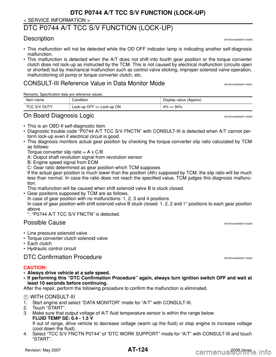
In case of gear position with no malfunctions: 1, 2, 3 and 4 positions
In case of gear position with shift solenoid valve B stuck closed: 1, 2, 2 and 1* positions to each gear position
above
*: “P0744 A/T TCC S/V FNCTN” is detected.
Possible CauseINFOID:0000000001703263
• Line pressure solenoid valve
• Torque converter clutch solenoid valve
• Each clutch
• Hydraulic control circuit
DTC Confirmation ProcedureINFOID:0000000001703264
CAUTION:
• Always drive vehicle at a safe speed.
• If performing this “DTC Confirmation Procedure” again, always turn ignition switch OFF and wait at
least 10 seconds before continuing.
After the repair, perform the following procedure to confirm the malfunction is eliminated.
WITH CONSULT-III
1. Start engine and select “DATA MONITOR” mode for “A/T” with CONSULT-III.
2. Touch “START”.
3. Make sure that output voltage of A/T fluid temperature sensor is within the range below.
FLUID TEMP SE: 0.4 - 1.5 V
If out of range, drive vehicle to decrease voltage (warm up the fluid) or stop engine to increase voltage
(cool down the fluid).
4. Select “TCC S/V FNCTN P0744” of “DTC WORK SUPPORT” mode for “A/T” with CONSULT-III and touch
“START”.
Item name Condition Display value (Approx)
TCC S/V DUTY Lock-up OFF ⇔ Lock-up ON 4% ⇔ 94%