brake rotor NISSAN TIIDA 2008 Service User Guide
[x] Cancel search | Manufacturer: NISSAN, Model Year: 2008, Model line: TIIDA, Model: NISSAN TIIDA 2008Pages: 2771, PDF Size: 60.61 MB
Page 794 of 2771
![NISSAN TIIDA 2008 Service User Guide TROUBLE DIAGNOSES FOR SYMPTOMS
BRC-29
< SERVICE INFORMATION >[ABS]
C
D
E
G
H
I
J
K
L
MA
B
BRC
N
O
P
TROUBLE DIAGNOSES FOR SYMPTOMS
ABS Works FrequentlyINFOID:0000000001703845
1.CHECK WARNING LAMP ACTI NISSAN TIIDA 2008 Service User Guide TROUBLE DIAGNOSES FOR SYMPTOMS
BRC-29
< SERVICE INFORMATION >[ABS]
C
D
E
G
H
I
J
K
L
MA
B
BRC
N
O
P
TROUBLE DIAGNOSES FOR SYMPTOMS
ABS Works FrequentlyINFOID:0000000001703845
1.CHECK WARNING LAMP ACTI](/img/5/57399/w960_57399-793.png)
TROUBLE DIAGNOSES FOR SYMPTOMS
BRC-29
< SERVICE INFORMATION >[ABS]
C
D
E
G
H
I
J
K
L
MA
B
BRC
N
O
P
TROUBLE DIAGNOSES FOR SYMPTOMS
ABS Works FrequentlyINFOID:0000000001703845
1.CHECK WARNING LAMP ACTIVATION
Make sure warning lamp remains off while driving.
OK or NG
OK >> GO TO 2.
NG >> Carry out self-diagnosis. Refer to BRC-18, "
CONSULT-III Function (ABS)".
2.CHECK WHEEL SENSORS
Check the following.
• Wheel sensor mounting for looseness
• Wheel sensors for physical damage
• Wheel sensor connectors for terminal damage or loose connections
• Sensor rotor and mount for physical damage
OK or NG
OK >> GO TO 3.
NG >> Repair or replace as necessary.
3.CHECK WHEEL BEARINGS
Check wheel bearing axial end play. Refer to FA X - 5 , "
On-Vehicle Inspection and Service" or RAX-4, "On-Vehi-
cle Inspection and Service".
OK or NG
OK >> GO TO 4.
NG >> Repair as necessary.
4.CHECK BRAKE FLUID PRESSURE
Check brake fluid pressure distribution.
Refer to BRC-16, "
Basic Inspection".
Is brake fluid pressure distribution normal?
YES >> Inspection End.
NO >> Perform Basic Inspection. Refer to BRC-16, "
Basic Inspection".
Unexpected Pedal ActionINFOID:0000000001703846
1.CHECK WARNING LAMP ACTIVATION
Make sure warning lamp remains off while driving.
OK or NG
OK >> GO TO 2.
NG >> Carry out self-diagnosis. Refer to BRC-18, "
CONSULT-III Function (ABS)".
2.CHECK BRAKE PEDAL STROKE
Check brake pedal stroke.
Is brake pedal stroke excessive?
YES >> Perform Basic Inspection. Refer to BRC-16, "Basic
Inspection".
NO >> GO TO 3.
3.CHECK CONNECTOR AND BRAKING PERFORMANCE
1. Disable ABS by disconnecting ABS actuator and electric unit (control unit) connector.
SBR540A
Page 795 of 2771
![NISSAN TIIDA 2008 Service User Guide BRC-30
< SERVICE INFORMATION >[ABS]
TROUBLE DIAGNOSES FOR SYMPTOMS
2. Drive vehicle and check brake operation.
NOTE:
• Stopping distance may be longer than vehicles without ABS when road condition i NISSAN TIIDA 2008 Service User Guide BRC-30
< SERVICE INFORMATION >[ABS]
TROUBLE DIAGNOSES FOR SYMPTOMS
2. Drive vehicle and check brake operation.
NOTE:
• Stopping distance may be longer than vehicles without ABS when road condition i](/img/5/57399/w960_57399-794.png)
BRC-30
< SERVICE INFORMATION >[ABS]
TROUBLE DIAGNOSES FOR SYMPTOMS
2. Drive vehicle and check brake operation.
NOTE:
• Stopping distance may be longer than vehicles without ABS when road condition is slippery.
• Driving the vehicle with the ABS actuator and electric unit (control unit) disconnected may induce DTCs
in electrical control units using CAN communication. After the inspection, clear all DTCs. Refer to LAN-
6, "System Description".
OK or NG
OK >> GO TO 4.
NG >> Perform Basic Inspection. Refer to BRC-16, "
Basic Inspection".
4.CHECK WHEEL SENSORS
Check the following.
• Wheel sensor mounting for looseness
• Wheel sensors for physical damage
• Wheel sensor connectors for terminal damage or loose connections
• Sensor rotor and mount for physical damage
OK or NG
OK >> Check ABS actuator and electric unit (control unit) connector terminals for deformation, discon-
nection, looseness or damage. Reconnect ABS actuator and electric unit (control unit) harness
connector. Then retest.
NG >> Repair or replace as necessary.
Long Stopping DistanceINFOID:0000000001703847
1.CHECK BASE BRAKING SYSTEM PERFORMANCE
1. Disable ABS by disconnecting ABS actuator and electric unit (control unit) connector.
2. Drive vehicle and check brake operation.
NOTE:
• Stopping distance may be longer than vehicles without ABS when road condition is slippery.
• Driving the vehicle with the ABS actuator and electric unit (control unit) disconnected may induce DTCs
in electrical control units using CAN communication. After the inspection, clear all DTCs. Refer to LAN-
6, "System Description".
OK or NG
OK >> Go to BRC-29, "ABS Works Frequently".
NG >> Perform Basic Inspection. Refer to BRC-16, "
Basic Inspection".
ABS Does Not WorkINFOID:0000000001703848
CAUTION:
The ABS does not operate when the vehicle speed is 10 km/h (6 MPH) or less.
1.CHECK WARNING LAMP ACTIVATION
Turn ignition switch ON and check for warning lamp activation.
• Warning lamp should activate for approximately 2 seconds after turning the ignition switch ON.
OK or NG
OK >> Carry out self-diagnosis. Refer to BRC-18, "CONSULT-III Function (ABS)".
NG >> Go to BRC-16, "
Basic Inspection".
Pedal Vibration or ABS Operation NoiseINFOID:0000000001703849
NOTE:
During ABS activation, pedal vibration may be felt and a noise may be heard. This is normal and does not indi-
cate a malfunction.
1.CHECK SYMPTOM
1. Apply brake.
2. Start engine.
Does the symptom occur only when engine is started?
YES >> Carry out self-diagnosis. Refer to BRC-18, "CONSULT-III Function (ABS)".
Page 1802 of 2771
FAX-6
< SERVICE INFORMATION >
FRONT WHEEL HUB AND KNUCKLE
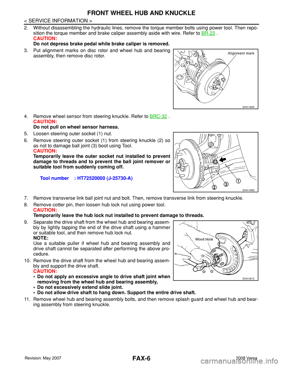
2. Without disassembling the hydraulic lines, remove the torque member bolts using power tool. Then repo-
sition the torque member and brake caliper assembly aside with wire. Refer to BR-23
.
CAUTION:
Do not depress brake pedal while brake caliper is removed.
3. Put alignment marks on disc rotor and wheel hub and bearing
assembly, then remove disc rotor.
4. Remove wheel sensor from steering knuckle. Refer to BRC-32
.
CAUTION:
Do not pull on wheel sensor harness.
5. Loosen steering outer socket (1) nut.
6. Remove steering outer socket (1) from steering knuckle (2) so
as not to damage ball joint (3) boot using Tool.
CAUTION:
Temporarily leave the outer socket nut installed to prevent
damage to threads and to prevent the ball joint remover or
suitable tool from suddenly coming off.
7. Remove transverse link ball joint nut and bolt. Then, remove transverse link from steering knuckle.
8. Remove cotter pin, then loosen hub lock nut using power tool.
CAUTION:
Temporarily leave the hub lock nut installed to prevent damage to threads.
9. Separate the drive shaft from the wheel hub and bearing assem-
bly by lightly tapping the end of the drive shaft using a hammer
or suitable tool, and then remove hub lock nut.
NOTE:
Use a suitable puller if wheel hub and bearing assembly and
drive shaft cannot be separated after performing the above pro-
cedure.
10. Remove the drive shaft from the wheel hub and bearing assem-
bly and support the drive shaft.
CAUTION:
• Do not apply an excessive angle to drive shaft joint when
removing from the wheel hub and bearing assembly,
• Do not excessively extend slide joint.
• Do not allow drive shaft to hang down. Support the entire drive shaft.
11. Remove wheel hub and bearing assembly bolts, and then remove splash guard and wheel hub and bear-
ing assembly from steering knuckle.
SDIA1480E
Tool number : HT72520000 (J-25730-A)
SGIA1298E
SDIA1821E
Page 1803 of 2771
FRONT WHEEL HUB AND KNUCKLE
FAX-7
< SERVICE INFORMATION >
C
E
F
G
H
I
J
K
L
MA
B
FA X
N
O
P
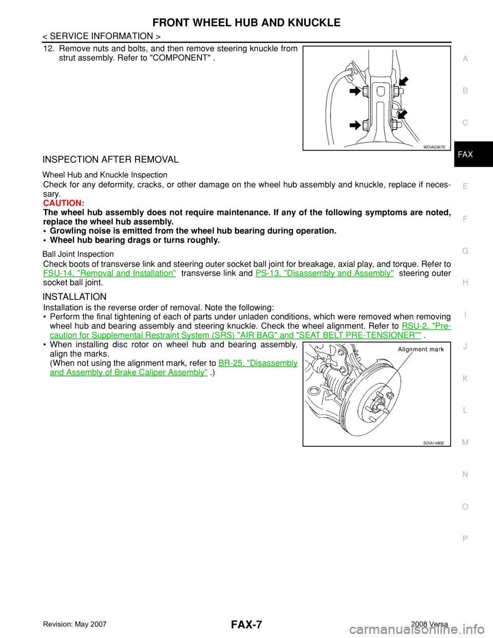
12. Remove nuts and bolts, and then remove steering knuckle from
strut assembly. Refer to "COMPONENT" .
INSPECTION AFTER REMOVAL
Wheel Hub and Knuckle Inspection
Check for any deformity, cracks, or other damage on the wheel hub assembly and knuckle, replace if neces-
sary.
CAUTION:
The wheel hub assembly does not require maintenance. If any of the following symptoms are noted,
replace the wheel hub assembly.
• Growling noise is emitted from the wheel hub bearing during operation.
• Wheel hub bearing drags or turns roughly.
Ball Joint Inspection
Check boots of transverse link and steering outer socket ball joint for breakage, axial play, and torque. Refer to
FSU-14, "
Removal and Installation" transverse link and PS-13, "Disassembly and Assembly" steering outer
socket ball joint.
INSTALLATION
Installation is the reverse order of removal. Note the following:
• Perform the final tightening of each of parts under unladen conditions, which were removed when removing
wheel hub and bearing assembly and steering knuckle. Check the wheel alignment. Refer to RSU-2, "
Pre-
caution for Supplemental Restraint System (SRS) "AIR BAG" and "SEAT BELT PRE-TENSIONER"" .
• When installing disc rotor on wheel hub and bearing assembly,
align the marks.
(When not using the alignment mark, refer to BR-25, "
Disassembly
and Assembly of Brake Caliper Assembly" .)
WDIA0367E
SDIA1480E
Page 2267 of 2771
![NISSAN TIIDA 2008 Service User Guide PERIODIC MAINTENANCE
MA-7
< SERVICE INFORMATION >
C
D
E
F
G
H
I
J
K
MA
B
MA
N
O
P
Abbreviations: R = Replace. I = Inspect. Correct or replace if necessary. [ ]: At the mileage intervals only
(1) After NISSAN TIIDA 2008 Service User Guide PERIODIC MAINTENANCE
MA-7
< SERVICE INFORMATION >
C
D
E
F
G
H
I
J
K
MA
B
MA
N
O
P
Abbreviations: R = Replace. I = Inspect. Correct or replace if necessary. [ ]: At the mileage intervals only
(1) After](/img/5/57399/w960_57399-2266.png)
PERIODIC MAINTENANCE
MA-7
< SERVICE INFORMATION >
C
D
E
F
G
H
I
J
K
MA
B
MA
N
O
P
Abbreviations: R = Replace. I = Inspect. Correct or replace if necessary. [ ]: At the mileage intervals only
(1) After 60,000 miles (96,000 km) or 48 months, inspect every 15,000 miles (24,000 km) or 12 months. Replace the drive belts if found
damaged.
(2) If operating mainly in dusty conditions, more frequent maintenance may be required.
(3) Maintenance-free item. For service procedures, go to the FL section.
(4) After 60,000 miles (96,000 km) or 48 months, replace every 30,000 miles (48,000 km) or 24 months.
(5) If valve noise increases, inspect valve clearance.
* Maintenance items and intervals with “*” are recommended by NISSAN for reliable vehicle operation. The owner need not perform
such maintenance in order to maintain the emission warranty or manufacturer recall liability. Other maintenance items and intervals are
required.
Chassis and Body Maintenance
Abbreviations: R = Replace. I = Inspect. Correct or replace if necessary. L = Lubricate.
MAINTENANCE OPERATIONMAINTENANCE INTERVAL
Reference Section -
Page or - Content Title Perform at number of
miles, kilometers or
months, whichever
comes first.Miles x
1,000
(km x
1,000)
Months33.75
(54)
2737.5
(60)
3041.25
(66)
3345
(72)
3648.75
(78)
3952.5
(84)
4256.25
(90)
4560
(96)
48
Drive beltNOTE
(1)I*MA-12
Air cleaner filterNOTE
(2)[R]MA-14
EVAP vapor linesI*MA-18
Fuel linesI*MA-14
Fuel filterNOTE
(3)—
Engine coolantNOTE
(4)R*MA-12
Engine oil R R R R R R R RMA-15
Engine oil filter (Use
genuine oil filter or
equivalent)R R R R RRRRMA-16
Spark plugs (Iridium/
platinum-tipped type)Replace every 105,000 miles (169,000 km)MA-17
Intake and exhaust
valve clearance NOTE
(5)EM-104
MAINTENANCE OPERATIONMAINTENANCE INTERVAL
Reference
Section -
Page or -
Content Title Perform at number of
miles, kilometers or
months, whichever
comes first.Miles x
1,000
(km x
1,000)
Months3.75
(6)
37.5
(12)
611 . 2 5
(18)
915
(24)
1218.75
(30)
1522.5
(36)
1826.25
(42)
2130
(48)
24
Brake lines & cables I IMA-24
Brake pads, rotors,
drums & liningsIIIIMA-24
Manual transaxle oil or
automatic transaxle
fluidNOTE (1) I IMA-19 , MA-
22 or MA-21
CVT fluid NOTE (2) I I
Steering gear & link-
age, axle & suspen-
sion partsIIIIMA-25
, PS-
12
Tire rotation NOTE (3)WT-6
Front drive shaft boots I I I IMA-26
Page 2268 of 2771
MA-8
< SERVICE INFORMATION >
PERIODIC MAINTENANCE
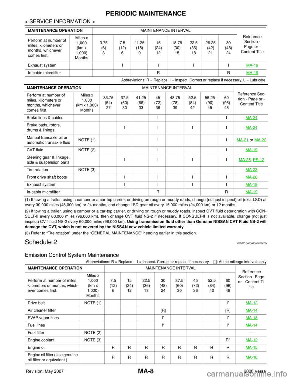
Abbreviations: R = Replace. I = Inspect. Correct or replace if necessary. L = Lubricate.
(1) If towing a trailer, using a camper or a car-top carrier, or driving on rough or muddy roads, change (not just inspect) oil (exc. LSD) at
every 30,000 miles (48,000 km) or 24 months, and change LSD gear oil every 15,000 miles (24,000 km) or 12 months.
(2) If towing a trailer, using a camper or a car-top carrier, or driving on rough or muddy roads, inspect CVT fluid deterioration with CON-
SULT-II every 60,000 miles (96,000 km), then change CVT fluid NS-2 if necessary. If CONSULT-II is not available, change (not just
inspect) CVT fluid NS-2 every 60,000 miles (96,000 km). Using transmission fluid other than Genuine NISSAN CVT Fluid NS-2 will
damage the CVT, which is not covered by the NISSAN new vehicle limited warranty.
(3) Refer to “Tire rotation” under the “GENERAL MAINTENANCE” heading earlier in this section.
Schedule 2INFOID:0000000001704724
Emission Control System Maintenance
Abbreviations: R = Replace. I = Inspect. Correct or replace if necessary. [ ]: At the mileage intervals only
Exhaust system I I I IMA-19
In-cabin microfilter R RMA-19
MAINTENANCE OPERATIONMAINTENANCE INTERVAL
Reference
Section -
Page or -
Content Title Perform at number of
miles, kilometers or
months, whichever
comes first.Miles x
1,000
(km x
1,000)
Months3.75
(6)
37.5
(12)
611 . 2 5
(18)
915
(24)
1218.75
(30)
1522.5
(36)
1826.25
(42)
2130
(48)
24
MAINTENANCE OPERATIONMAINTENANCE INTERVAL
Reference Sec-
tion - Page or -
Content Title Perform at number of
miles, kilometers or
months, whichever
comes first.Miles x
1,000
(km x 1,000)
Months33.75
(54)
2737.5
(60)
3041.25
(66)
3345
(72)
3648.75
(78)
3952.5
(84)
4256.25
(90)
4560
(96)
48
Brake lines & cables I IMA-24
Brake pads, rotors,
drums & liningsII I IMA-24
Manual transaxle oil or
automatic transaxle fluidNOTE (1) I IMA-21 or MA-22
CVT fluid NOTE (2) I IMA-19
Steering gear & linkage,
axle & suspension partsII I IMA-25, PS-12
Tire rotation NOTE (3)MA-23
Front drive shaft boots I I I IMA-26
Exhaust system I I I IMA-19
In-cabin microfilter R RMA-19
MAINTENANCE OPERATIONMAINTENANCE INTERVAL
Reference
Section - Page
or - Content Ti-
tle Perform at number of miles,
kilometers or months, which-
ever comes first.Miles x
1,000
(km x
1,000)
Months7.5
(12)
615
(24)
1222.5
(36)
1830
(48)
2437.5
(60)
3045
(72)
3652.5
(84)
4260
(96)
48
Drive belt NOTE (1) I*MA-12
Air cleaner filter [R] [R]MA-14
EVAP vapor lines I* I*MA-18
Fuel lines I* I*MA-14
Fuel filter NOTE (2)—
Engine coolant NOTE (3) R*MA-12
Engine oil RR R RRRRRMA-15
Engine oil filter (Use genuine
oil filter or equivalent.)RR R RRRRRMA-16
Page 2269 of 2771
PERIODIC MAINTENANCE
MA-9
< SERVICE INFORMATION >
C
D
E
F
G
H
I
J
K
MA
B
MA
N
O
P
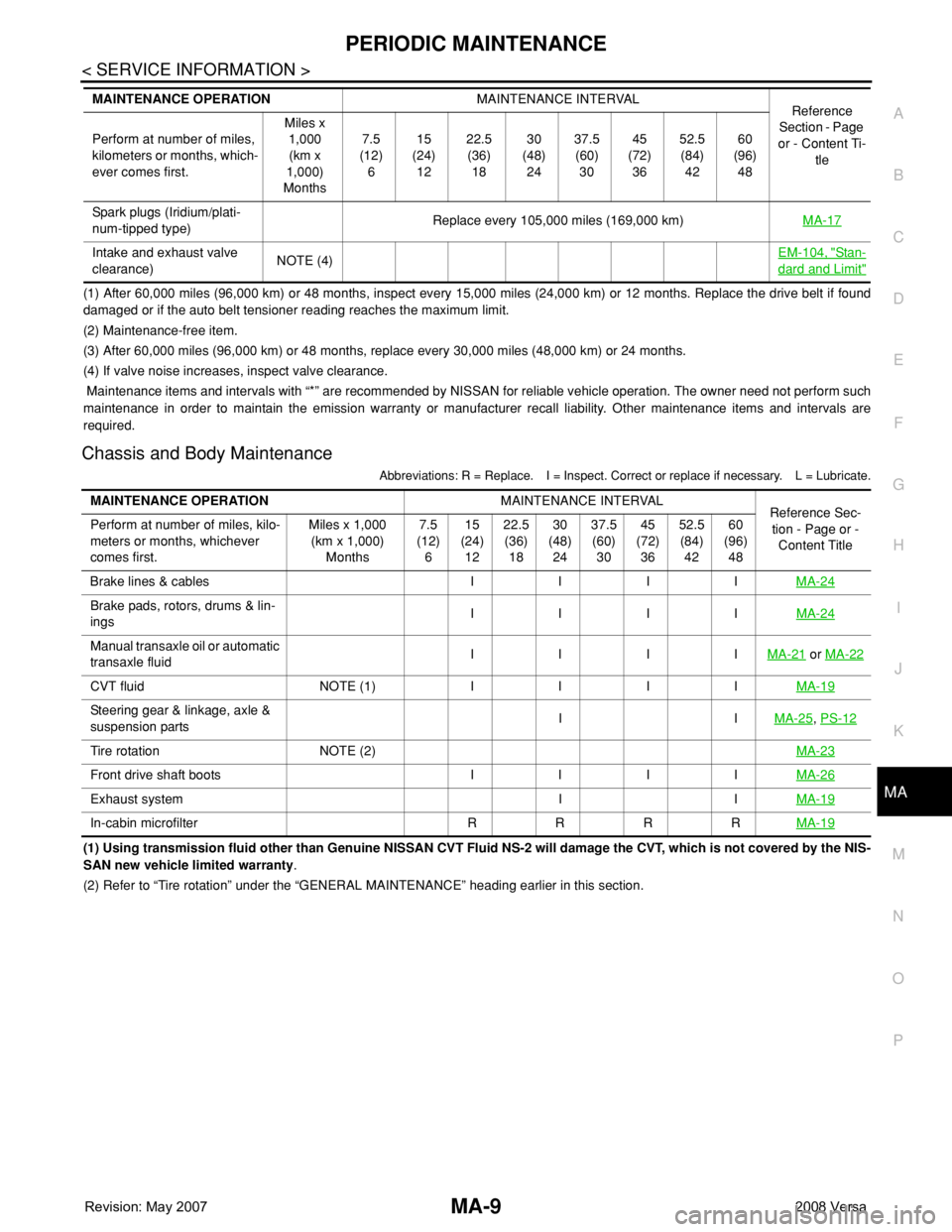
(1) After 60,000 miles (96,000 km) or 48 months, inspect every 15,000 miles (24,000 km) or 12 months. Replace the drive belt if found
damaged or if the auto belt tensioner reading reaches the maximum limit.
(2) Maintenance-free item.
(3) After 60,000 miles (96,000 km) or 48 months, replace every 30,000 miles (48,000 km) or 24 months.
(4) If valve noise increases, inspect valve clearance.
Maintenance items and intervals with “*” are recommended by NISSAN for reliable vehicle operation. The owner need not perform such
maintenance in order to maintain the emission warranty or manufacturer recall liability. Other maintenance items and intervals are
required.
Chassis and Body Maintenance
Abbreviations: R = Replace. I = Inspect. Correct or replace if necessary. L = Lubricate.
(1) Using transmission fluid other than Genuine NISSAN CVT Fluid NS-2 will damage the CVT, which is not covered by the NIS-
SAN new vehicle limited warranty.
(2) Refer to “Tire rotation” under the “GENERAL MAINTENANCE” heading earlier in this section. Spark plugs (Iridium/plati-
num-tipped type)Replace every 105,000 miles (169,000 km)MA-17
Intake and exhaust valve
clearance)NOTE (4)EM-104, "Sta n-
dard and Limit"
MAINTENANCE OPERATIONMAINTENANCE INTERVAL
Reference
Section - Page
or - Content Ti-
tle Perform at number of miles,
kilometers or months, which-
ever comes first.Miles x
1,000
(km x
1,000)
Months7.5
(12)
615
(24)
1222.5
(36)
1830
(48)
2437.5
(60)
3045
(72)
3652.5
(84)
4260
(96)
48
MAINTENANCE OPERATIONMAINTENANCE INTERVAL
Reference Sec-
tion - Page or -
Content Title Perform at number of miles, kilo-
meters or months, whichever
comes first.Miles x 1,000
(km x 1,000)
Months7.5
(12)
615
(24)
1222.5
(36)
1830
(48)
2437.5
(60)
3045
(72)
3652.5
(84)
4260
(96)
48
Brake lines & cables I I I IMA-24
Brake pads, rotors, drums & lin-
ings IIIIMA-24
Manual transaxle oil or automatic
transaxle fluidIIIIMA-21 or MA-22
CVT fluid NOTE (1) IIIIMA-19
Steering gear & linkage, axle &
suspension partsIIMA-25, PS-12
Tire rotation NOTE (2)MA-23
Front drive shaft boots I I I IMA-26
Exhaust system I IMA-19
In-cabin microfilter R R R RMA-19
Page 2283 of 2771
CHASSIS AND BODY MAINTENANCE
MA-23
< SERVICE INFORMATION >
C
D
E
F
G
H
I
J
K
MA
B
MA
N
O
P
2. Stop engine.
3. Drain A/T fluid by removing the drain plug. Reinstall the drain plug to the specified torque.
CAUTION:
Do not reuse drain plug gasket.
4. Refill the transaxle with new specified A/T fluid through the A/T fluid charging pipe. Always refill the tran-
saxle with the same volume of A/T fluid that was drained out.
5. Run engine at idle speed for 5 minutes.
6. Check A/T fluid level and condition. Refer to MA-22, "
Checking A/T Fluid" .
Balancing WheelsINFOID:0000000001704749
Adjust wheel balance using road wheel center.
CAUTION:
• Be careful not to scratch the road wheel during removal.
• Use clip-on type wheel balance weights only.
Wheel balance (Maximum allowable unbalance):
RotationINFOID:0000000001704750
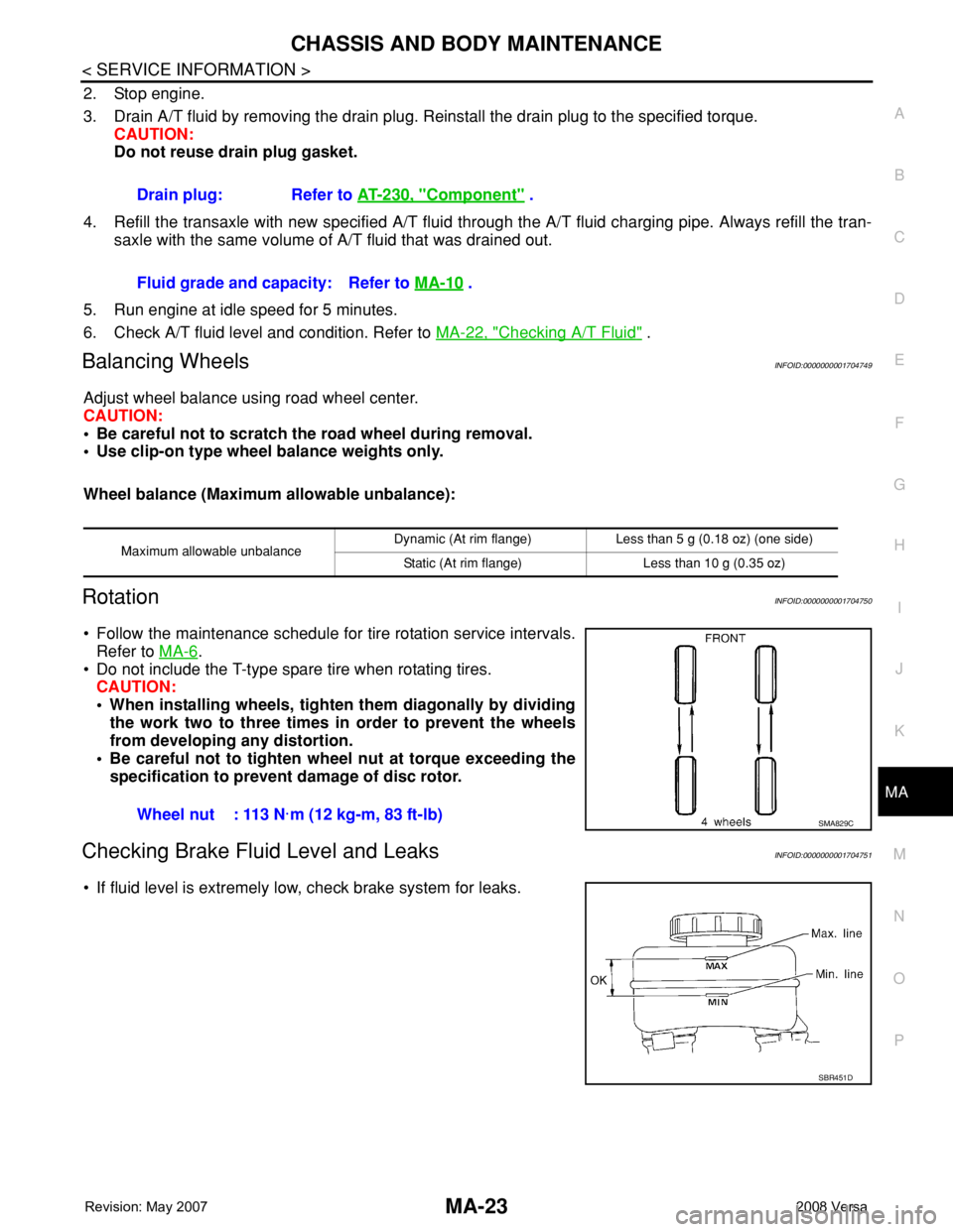
• Follow the maintenance schedule for tire rotation service intervals.
Refer to MA-6
.
• Do not include the T-type spare tire when rotating tires.
CAUTION:
• When installing wheels, tighten them diagonally by dividing
the work two to three times in order to prevent the wheels
from developing any distortion.
• Be careful not to tighten wheel nut at torque exceeding the
specification to prevent damage of disc rotor.
Checking Brake Fluid Level and LeaksINFOID:0000000001704751
• If fluid level is extremely low, check brake system for leaks.Drain plug: Refer to AT-230, "
Component" .
Fluid grade and capacity: Refer to MA-10
.
Maximum allowable unbalanceDynamic (At rim flange) Less than 5 g (0.18 oz) (one side)
Static (At rim flange) Less than 10 g (0.35 oz)
Wheel nut : 113 N·m (12 kg-m, 83 ft-lb)SMA829C
SBR451D
Page 2284 of 2771
MA-24
< SERVICE INFORMATION >
CHASSIS AND BODY MAINTENANCE
Checking Brake Line and Cables
INFOID:0000000001704752
• Check brake fluid lines and parking brake cables for improper
attachment, leaks, chafing, abrasions, deterioration, etc.
Changing Brake FluidINFOID:0000000001704753
1. Drain brake fluid from each bleed valve.
2. Refill until new brake fluid comes out from each bleed valve.
Use same procedure as in bleeding hydraulic system to refill
brake fluid.
Refer to BR-8, "
Bleeding Brake System" .
• Refill with recommended Genuine Brake Fluid or equivalent
DOT 3 (US FMVSS No. 116).
Refer to MA-10
.
• Never reuse drained brake fluid.
• Be careful not to splash brake fluid on painted areas.
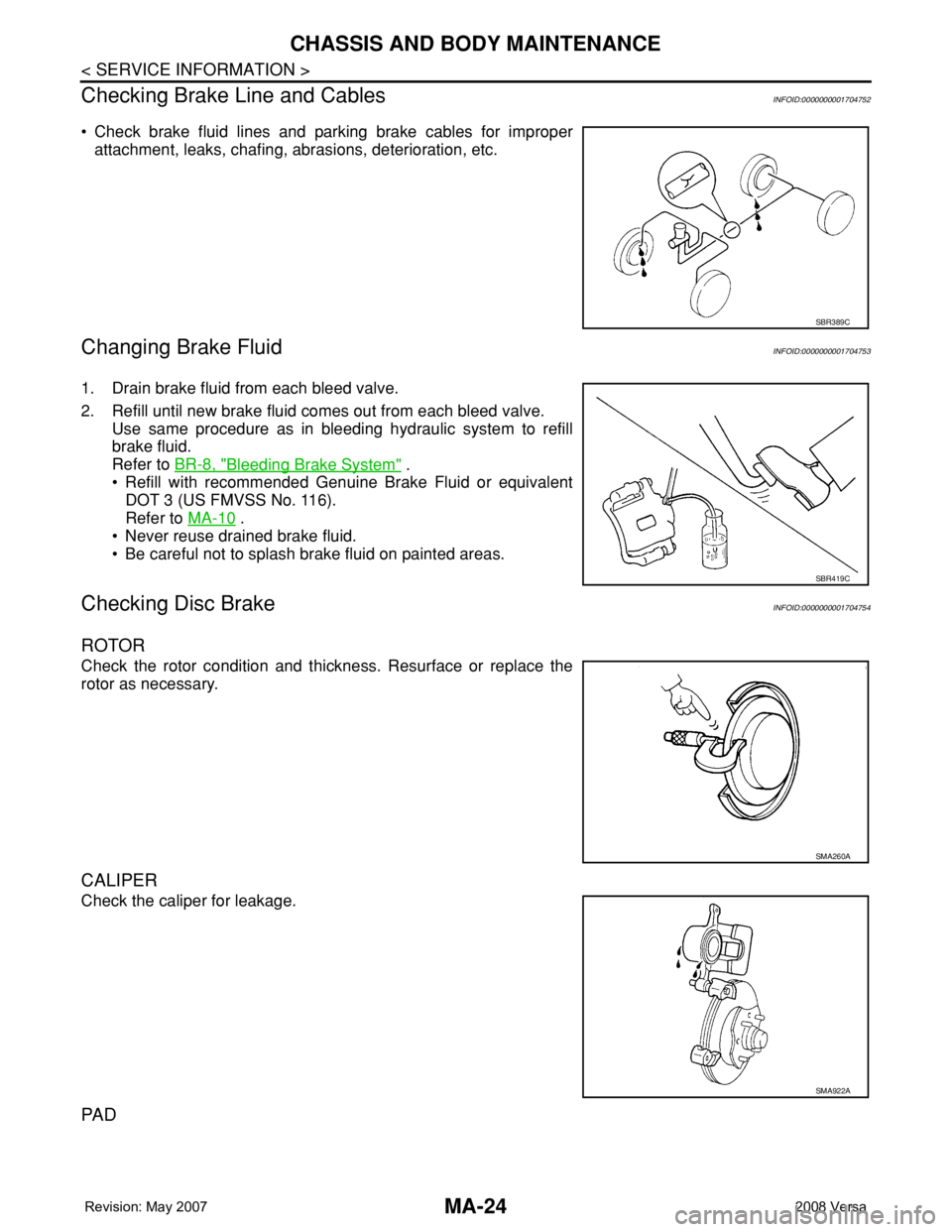
Checking Disc BrakeINFOID:0000000001704754
ROTOR
Check the rotor condition and thickness. Resurface or replace the
rotor as necessary.
CALIPER
Check the caliper for leakage.
PA D
SBR389C
SBR419C
SMA260A
SMA922A