display NISSAN TIIDA 2008 Service User Guide
[x] Cancel search | Manufacturer: NISSAN, Model Year: 2008, Model line: TIIDA, Model: NISSAN TIIDA 2008Pages: 2771, PDF Size: 60.61 MB
Page 89 of 2771

TROUBLE DIAGNOSIS
AT-77
< SERVICE INFORMATION >
D
E
F
G
H
I
J
K
L
MA
B
AT
N
O
P
CAN DIAGNOSTIC SUPPORT MONITOR MODE
Refer to LAN-12, "CAN Diagnostic Support Monitor".
DTC WORK SUPPORT MODE
Display Items List
*SHIFT S/V A (ON/OFF) — —
Displays status of check signal (reinput
signal) for TCM control signal output. Re-
mains unchanged when solenoid valves
are open or shorted. *SHIFT S/V B (ON/OFF) — —
*OVRRUN/C S/V (ON/OFF) — —
HOLD SW (ON/OFF) X — Not mounted but displayed.
BRAKE SW (ON/OFF) X —Stop lamp switch (Signal input with CAN
communication)
GEAR — XGear position recognized by the TCM up-
dated after gear-shifting
SLCT LVR POSI — XSelector lever position is recognized by
the TCM.
For fail-safe operation, the specific value
used for control is displayed.
VEHICLE SPEED (km/h) — X Vehicle speed recognized by the TCM.
THROTTLE POSI (0.0/8) — XDegree of opening for accelerator recog-
nized by the TCM
For fail-safe operation, the specific value
used for control is displayed.
LINE PRES DTY (%) — X
TCC S/V DUTY (%) — X
SHIFT S/V A (ON/OFF) — X
SHIFT S/V B (ON/OFF) — X
OVERRUN/C S/V (ON/OFF) — X
SELF-D DP LMP (ON/OFF) — X
TC SLIP RATIO (0.000) — —
TC SLIP SPEED (rpm) — —Difference between engine speed and
torque converter input shaft speed
Voltage (V) — —Displays the value measured by the volt-
age probe.
Frequency (Hz) — —
The value measured by the pulse probe
is displayed. DUTY-HI (high) (%) — —
DUTY-LOW (low) (%) — —
PLS WIDTH-HI (ms) — —
PLS WIDTH-LOW (ms) — —Monitored item (Unit)Monitor Item Selection
Remarks
TCM INPUT
SIGNALSMAIN SIG-
NALSSELEC-
TION FROM
MENU
Page 98 of 2771

AT-86
< SERVICE INFORMATION >
DTC P0705 PARK/NEUTRAL POSITION (PNP) SWITCH
DTC P0705 PARK/NEUTRAL POSITION (PNP) SWITCH
DescriptionINFOID:0000000001703201
• The PNP switch assembly includes a transaxle range switch.
• The transaxle range switch detects the selector lever position and sends a signal to the TCM.
CONSULT-III Reference Value in Data Monitor ModeINFOID:0000000001703202
On Board Diagnosis LogicINFOID:0000000001703203
• This is an OBD-II self-diagnostic item.
• Diagnostic trouble code “P0705 PNP SW/CIRC” with CONSULT-III is detected when TCM does not receive
the correct voltage signal from the switch based on the gear position.
Possible CauseINFOID:0000000001703204
• Harness or connectors
[The PNP switch circuit is open or shorted.]
• PNP switch
DTC Confirmation ProcedureINFOID:0000000001703205
CAUTION:
• Always drive vehicle at a safe speed.
• If performing this “DTC Confirmation Procedure” again, always turn ignition switch OFF and wait at
least 10 seconds before continuing.
After the repair, perform the following procedure to confirm the malfunction is eliminated.
WITH CONSULT-III
1. Turn ignition switch ON. (Do not start engine.)
2. Select “DATA MONITOR” mode for “A/T” with CONSULT-III.
3. Touch “START”.
4. Start engine and maintain the following conditions for at least 5 consecutive seconds.
VEHICLE SPEED: 10 km/h (6 MPH) or more
THROTTLE POSI: More than 1.0/8
SLCT LVR POSI: “D” position
5. If the check result is NG, go to AT-88, "
Diagnosis Procedure" .
WITH GST
Follow the procedure “WITH CONSULT-III”.
Item name Condition Display value
PN POSI SWWhen setting selector lever to “N” or “P” position. ON
When setting selector lever to other positions. OFF
R POSITION SWWhen setting selector lever to “R” position. ON
When setting selector lever to other positions. OFF
D POSITION SWWhen setting selector lever to “D” position. ON
When setting selector lever to other positions. OFF
2 POSITION SWWhen setting selector lever to “2” position. ON
When setting selector lever to other positions. OFF
1 POSITION SWWhen setting selector lever to “1” position. ON
When setting selector lever to other positions. OFF
Page 100 of 2771
AT-88
< SERVICE INFORMATION >
DTC P0705 PARK/NEUTRAL POSITION (PNP) SWITCH
Diagnosis Procedure
INFOID:0000000001703207
1.CHECK INPUT SIGNAL
With CONSULT-III
1. Turn ignition switch ON. (Do not start engine.)
2. Select “TCM INPUT SIGNALS” in “DATA MONITOR” mode for “A/T” with CONSULT-III.
3. Read out “P·N”, “R”, “D”, “2” and “1” position switches moving selector lever to each position.
OK or NG
OK >> GO TO 6.
NG >> GO TO 3.
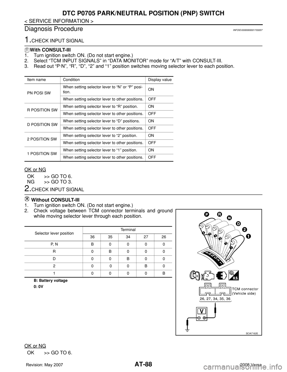
2.CHECK INPUT SIGNAL
Without CONSULT-III
1. Turn ignition switch ON. (Do not start engine.)
2. Check voltage between TCM connector terminals and ground
while moving selector lever through each position.
B: Battery voltage
0: 0V
OK or NG
OK >> GO TO 6.
Item name Condition Display value
PN POSI SWWhen setting selector lever to “N” or “P” posi-
tion.ON
When setting selector lever to other positions. OFF
R POSITION SWWhen setting selector lever to “R” position. ON
When setting selector lever to other positions. OFF
D POSITION SWWhen setting selector lever to “D” positions. ON
When setting selector lever to other positions. OFF
2 POSITION SWWhen setting selector lever to “2” position. ON
When setting selector lever to other positions. OFF
1 POSITION SWWhen setting selector lever to “1” position. ON
When setting selector lever to other positions. OFF
Selector lever positionTe r m i n a l
36 35 34 27 26
P, N B0000
R 0B000
D00B00
20 00B0
1 0000B
SCIA7162E
Page 103 of 2771
DTC P0710 A/T FLUID TEMPERATURE SENSOR CIRCUIT
AT-91
< SERVICE INFORMATION >
D
E
F
G
H
I
J
K
L
MA
B
AT
N
O
P
DTC P0710 A/T FLUID TEMPERATURE SENSOR CIRCUIT
DescriptionINFOID:0000000001703209
The A/T fluid temperature sensor detects the A/T fluid temperature and sends a signal to the TCM.
CONSULT-III Reference Value in Data Monitor ModeINFOID:0000000001703210
Remarks: Specification data are reference values.
On Board Diagnosis LogicINFOID:0000000001703211
• This is an OBD-II self-diagnostic item.
• Diagnostic trouble code “P0710 ATF TEMP SEN/CIRC” with CONSULT-III is detected when TCM receives
an excessively low or high voltage from the sensor.
Possible CauseINFOID:0000000001703212
• Harness or connector
(The sensor circuit is open or shorted.)
• A/T fluid temperature sensor
DTC Confirmation ProcedureINFOID:0000000001703213
CAUTION:
• Always drive vehicle at a safe speed.
• If performing this “DTC Confirmation Procedure” again, always turn ignition switch OFF and wait at
least 10 seconds before continuing.
After the repair, perform the following procedure to confirm the malfunction is eliminated.
WITH CONSULT-III
1. Turn ignition switch ON and select “DATA MONITOR” mode for “A/T” with CONSULT-III.
2. Touch “START”.
3. Start engine and maintain the following conditions for at least 10 minutes (Total). (It is not necessary to
maintain continuously.)
ENGINE SPEED: 450 rpm or more
VEHICLE SPEED: 10 km/h (6 MPH) or more
THROTTLE POSI: More than 1.0/8
SLCT LVR POSI: “D” position
4. If the check result is NG, go to AT-92, "
Diagnosis Procedure".
WITH GST
Follow the procedure “With CONSULT-III”.
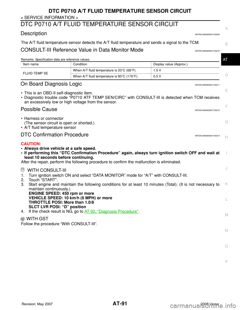
Item name Condition Display value (Approx.)
FLUID TEMP SEWhen A/T fluid temperature is 20°C (68°F). 1.5 V
When A/T fluid temperature is 80°C (176°F). 0.5 V
Page 105 of 2771
DTC P0710 A/T FLUID TEMPERATURE SENSOR CIRCUIT
AT-93
< SERVICE INFORMATION >
D
E
F
G
H
I
J
K
L
MA
B
AT
N
O
P
With CONSULT-III
1. Start engine.
2. Select “TCM INPUT SIGNALS” in “DATA MONITOR” mode for “A/T” with CONSULT-III.
3. Read out the value of “FLUID TEMP SE”.
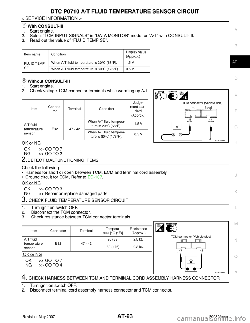
Without CONSULT-III
1. Start engine.
2. Check voltage TCM connector terminals while warming up A/T.
OK or NG
OK >> GO TO 7.
NG >> GO TO 2.
2.DETECT MALFUNCTIONING ITEMS
Check the following.
• Harness for short or open between TCM, ECM and terminal cord assembly
• Ground circuit for ECM, Refer to EC-137
.
OK or NG
OK >> GO TO 3.
NG >> Repair or replace damaged parts.
3. CHECK FLUID TEMPERATURE SENSOR CIRCUIT
1. Turn ignition switch OFF.
2. Disconnect the TCM connector.
3. Check resistance between TCM connector terminals.
OK or NG
OK >> GO TO 7.
NG >> GO TO 4.
4. CHECK HARNESS BETWEEN TCM AND TERMINAL CORD ASSEMBLY HARNESS CONNECTOR
1. Turn ignition switch OFF.
2. Disconnect terminal cord assembly harness connector and TCM connector.
Item name ConditionDisplay value
(Approx.)
FLUID TEMP
SEWhen A/T fluid temperature is 20°C (68°F). 1.5 V
When A/T fluid temperature is 80°C (176°F). 0.5 V
ItemConnec-
torTerminal ConditionJudge-
ment stan-
dard
(Approx.)
A/T fluid
temperature
sensorE32 47 - 42When A/T fluid tempera-
ture is 20°C (68°F).1.5 V
When A/T fluid tempera-
ture is 80°C (176°F).0.5 V
SCIA2658E
Item Connector Terminal Te m p e r a -
ture [°C (°F)]Resistance
(Approx.)
A/T fluid
temperature
sensorE32 47 - 4220 (68) 2.5 kΩ
80 (176) 0.3 kΩ
SCIA2338E
Page 108 of 2771
AT-96
< SERVICE INFORMATION >
DTC P0720 VEHICLE SPEED SENSOR A/T (REVOLUTION SENSOR)
DTC P0720 VEHICLE SPEED SENSOR A/T (REVOLUTION SENSOR)
DescriptionINFOID:0000000001703217
The revolution sensor detects the revolution of the idler gear parking pawl lock gear and emits a pulse signal.
The pulse signal is sent to the TCM which converts it into vehicle speed.
CONSULT-III Reference Value in Data Monitor ModeINFOID:0000000001703218
Remarks: Specification data are reference values.
On Board Diagnosis LogicINFOID:0000000001703219
• This is an OBD-II self-diagnostic item.
• Diagnostic trouble code “P0720 VHCL SPEED SEN-AT” with CONSULT-III or 1st judgement flicker without
CONSULT-III is detected when TCM does not receive the proper voltage signal from the sensor.
Possible CauseINFOID:0000000001703220
• Harness or connector
(The sensor circuit is open or shorted.)
• Revolution sensor
DTC Confirmation ProcedureINFOID:0000000001703221
CAUTION:
• Always drive vehicle at a safe speed.
• Be careful not to rev engine into the red zone on the tachometer.
• If performing this “DTC Confirmation Procedure” again, always turn ignition switch OFF and wait at
least 10 seconds before continuing.
After the repair, perform the following procedure to confirm the malfunction is eliminated.
WITH CONSULT-III
1. Turn ignition switch ON and select “DATA MONITOR” mode for “A/T” with CONSULT-III.
2. Touch “START”.
3. Drive vehicle and check for an increase of “VHCL/S SE-MTR” value.
If the check result is NG, go to AT-98, "
Diagnosis Procedure" .
If the check result is OK, go to following step.
4. Select “DATA MONITOR” mode for “A/T” with CONSULT-III.
5. Touch “START”.
6. Start engine and maintain the following conditions for at least 5 consecutive seconds.
VEHICLE SPEED: 30 km/h (19 MPH) or more
THROTTLE POSI: More than 1.0/8
SLCT LVR POSI: “D” position
Driving location: Driving the vehicle uphill (increased engine load) will help maintain the driving
conditions required for this test.
If the check result is NG, go to AT-98, "
Diagnosis Procedure" .
If the check result is OK, go to following step.
7. Maintain the following conditions for at least 5 consecutive seconds.
ENGINE SPEED: 3,500 rpm or more
THROTTLE POSI: More than 1.0/8
SLCT LVR POSI: “D” position
Driving location: Driving the vehicle uphill (increased engine load) will help maintain the driving
conditions required for this test.
WITH GST
Follow the procedure “WITH CONSULT-III”.
WITHOUT CONSULT-III
1. Start engine.
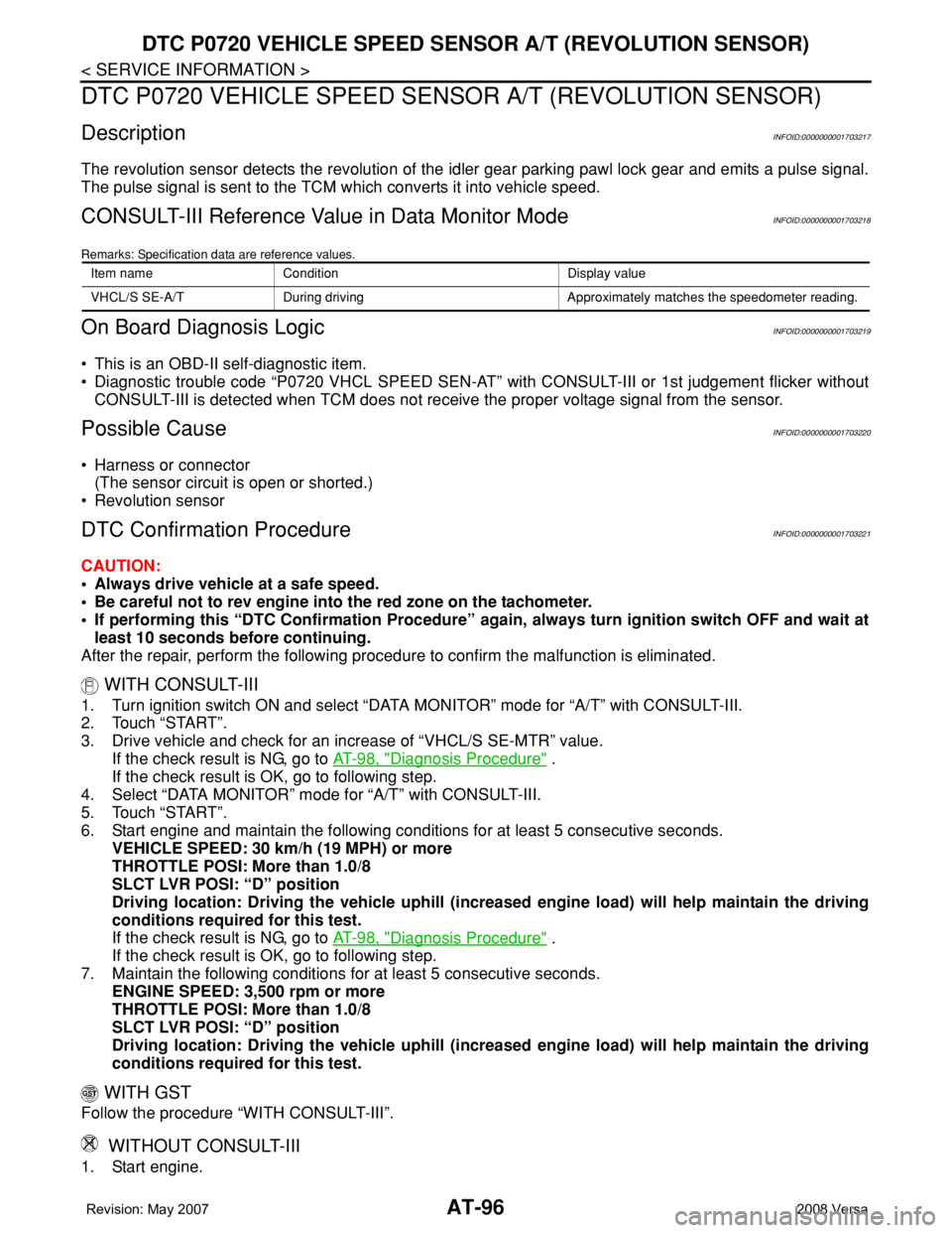
Item name Condition Display value
VHCL/S SE-A/T During driving Approximately matches the speedometer reading.
Page 113 of 2771
DTC P0725 ENGINE SPEED SIGNAL
AT-101
< SERVICE INFORMATION >
D
E
F
G
H
I
J
K
L
MA
B
AT
N
O
P
DTC P0725 ENGINE SPEED SIGNAL
DescriptionINFOID:0000000001703224
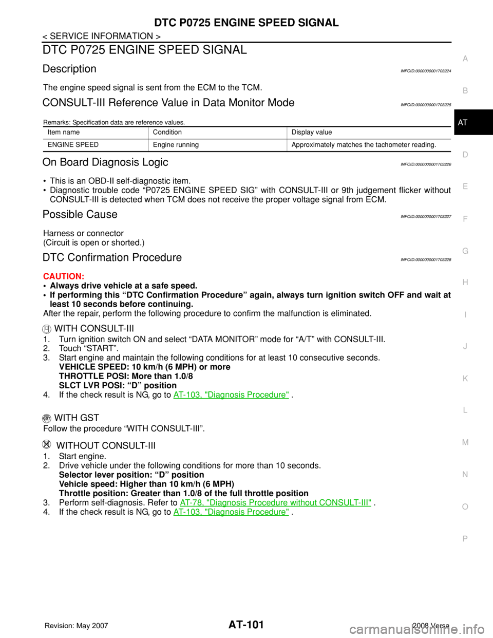
The engine speed signal is sent from the ECM to the TCM.
CONSULT-III Reference Value in Data Monitor ModeINFOID:0000000001703225
Remarks: Specification data are reference values.
On Board Diagnosis LogicINFOID:0000000001703226
• This is an OBD-II self-diagnostic item.
• Diagnostic trouble code “P0725 ENGINE SPEED SIG” with CONSULT-III or 9th judgement flicker without
CONSULT-III is detected when TCM does not receive the proper voltage signal from ECM.
Possible CauseINFOID:0000000001703227
Harness or connector
(Circuit is open or shorted.)
DTC Confirmation ProcedureINFOID:0000000001703228
CAUTION:
• Always drive vehicle at a safe speed.
• If performing this “DTC Confirmation Procedure” again, always turn ignition switch OFF and wait at
least 10 seconds before continuing.
After the repair, perform the following procedure to confirm the malfunction is eliminated.
WITH CONSULT-III
1. Turn ignition switch ON and select “DATA MONITOR” mode for “A/T” with CONSULT-III.
2. Touch “START”.
3. Start engine and maintain the following conditions for at least 10 consecutive seconds.
VEHICLE SPEED: 10 km/h (6 MPH) or more
THROTTLE POSI: More than 1.0/8
SLCT LVR POSI: “D” position
4. If the check result is NG, go to AT-103, "
Diagnosis Procedure" .
WITH GST
Follow the procedure “WITH CONSULT-III”.
WITHOUT CONSULT-III
1. Start engine.
2. Drive vehicle under the following conditions for more than 10 seconds.
Selector lever position: “D” position
Vehicle speed: Higher than 10 km/h (6 MPH)
Throttle position: Greater than 1.0/8 of the full throttle position
3. Perform self-diagnosis. Refer to AT-78, "
Diagnosis Procedure without CONSULT-III" .
4. If the check result is NG, go to AT-103, "
Diagnosis Procedure" .
Item name Condition Display value
ENGINE SPEED Engine running Approximately matches the tachometer reading.
Page 115 of 2771
DTC P0725 ENGINE SPEED SIGNAL
AT-103
< SERVICE INFORMATION >
D
E
F
G
H
I
J
K
L
MA
B
AT
N
O
P
Diagnosis ProcedureINFOID:0000000001703230
1.CHECK DTC WITH ECM
Check DTC with CONSULT-III “ENGINE”.
Turn ignition switch ON and select “SELF-DIAGNOSTIC RESULTS” mode for “ENGINE” with CONSULT-III.
Refer to EC-109, "
CONSULT-II Function (ENGINE)" .
OK or NG
OK >> GO TO 2.
NG >> Check ignition signal circuit for engine control. Refer to EC-531
.
2.CHECK INPUT SIGNAL
With CONSULT-III
1. Start engine.
2. Select “TCM INPUT SIGNALS” in “DATA MONITOR” mode for “A/T” with CONSULT-III.
3. Read out the value of “ENGINE SPEED”. Check engine speed changes according to throttle position.
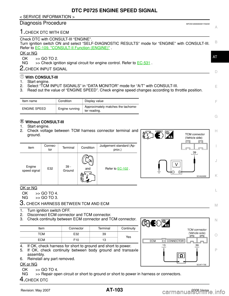
Without CONSULT-III
1. Start engine.
2. Check voltage between TCM harness connector terminal and
ground.
OK or NG
OK >> GO TO 4.
NG >> GO TO 3.
3. CHECK HARNESS BETWEEN TCM AND ECM
1. Turn ignition switch OFF.
2. Disconnect ECM connector and TCM connector.
3. Check continuity between ECM connector and TCM connector.
4. If OK, check harness for short to ground and short to power.
5. If OK, check continuity between body ground and transaxle
assembly.
6. Reinstall any part removed.
OK or NG
OK >> GO TO 4.
NG >> Repair open circuit or short to ground or short to power in harness or connectors.
4.CHECK DTC
Item name Condition Display value
ENGINE SPEED Engine runningApproximately matches the tachome-
ter reading.
itemConnec-
torTerminal ConditionJudgement standard (Ap-
prox.)
Engine
speed signalE3239 -
Ground
and Refer to EC-102
.
SCIA3265E
Item Connector Terminal Continuity
TCM E32 39
Ye s
ECM F10 13
SCIA7173E
Page 118 of 2771
AT-106
< SERVICE INFORMATION >
DTC P0731 A/T 1ST GEAR FUNCTION
5. Accelerate vehicle to 20 to 25 km/h (12 to 16 MPH) under the following conditions and release the accel-
erator pedal completely.
THROTTLE POSI: Less than 1.0/8 (at all times during step 4)
SLCT LVR POSI: “D” position
-Make sure that “GEAR” shows “2” after releasing pedal.
6. Depress accelerator pedal to WOT (more than 7.0/8 of “THROTTLE POSI”) quickly from a speed of 20 to
25 km/h (12 to 16 MPH) until “TESTING” changes to “STOP VEHICLE” or “COMPLETED”. (It will take
approximately 3 seconds.)
If the check result NG appears on CONSULT-III screen, go to AT-106, "
Diagnosis Procedure".
If “STOP VEHICLE” appears on CONSULT-III screen, go to the following step.
-Make sure that “GEAR” shows “1” when depressing accelerator pedal to WOT.
-If “TESTING” does not appear on CONSULT-III for a long time, select “SELF-DIAG RESULTS” for
“A/T”. In case a DTC other than “P0731 A/T 1ST GR FNCTN” is shown, refer to AT-73, "
CONSULT-III
Function (A/T)".
7. Stop vehicle.
8. Follow the instruction displayed. (Check for normal shifting referring to the table below.)
9. Make sure that “OK” is displayed. (If “NG” is displayed, refer to “Diagnostic Procedure”.)
Refer to AT-106, "
Diagnosis Procedure".
Refer to AT-61, "
Vehicle Speed at Which Gear Shifting Occurs".
WITH GST
Follow the procedure “WITH CONSULT-III”.
Diagnosis ProcedureINFOID:0000000001703235
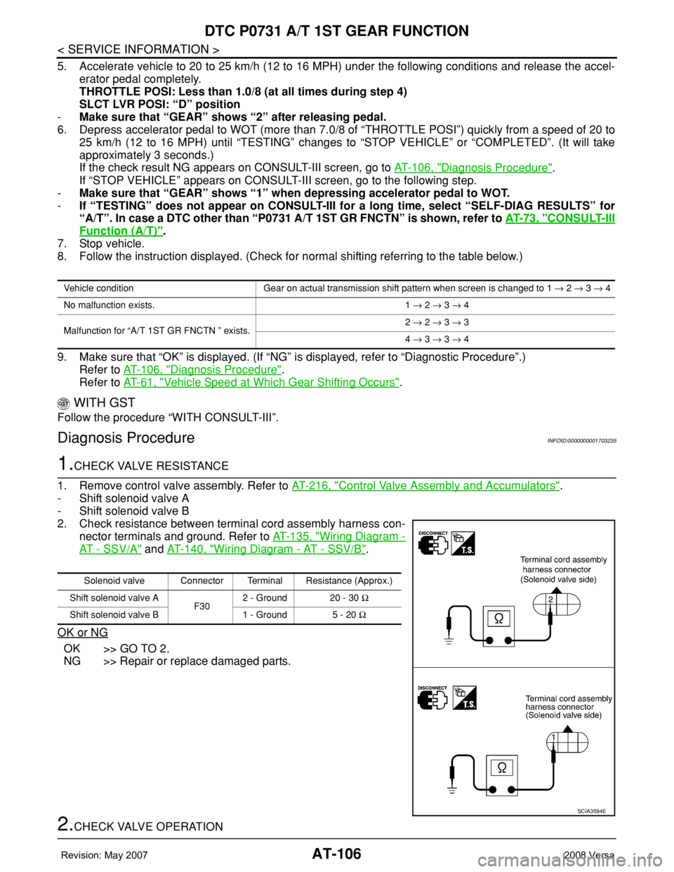
1.CHECK VALVE RESISTANCE
1. Remove control valve assembly. Refer to AT-216, "
Control Valve Assembly and Accumulators".
- Shift solenoid valve A
- Shift solenoid valve B
2. Check resistance between terminal cord assembly harness con-
nector terminals and ground. Refer to AT-135, "
Wiring Diagram -
AT - SSV/A" and AT-140, "Wiring Diagram - AT - SSV/B".
OK or NG
OK >> GO TO 2.
NG >> Repair or replace damaged parts.
2.CHECK VALVE OPERATION
Vehicle condition Gear on actual transmission shift pattern when screen is changed to 1 → 2 → 3 → 4
No malfunction exists. 1 → 2 → 3 → 4
Malfunction for “A/T 1ST GR FNCTN ” exists.2 → 2 → 3 → 3
4 → 3 → 3 → 4
Solenoid valve Connector Terminal Resistance (Approx.)
Shift solenoid valve A
F302 - Ground 20 - 30 Ω
Shift solenoid valve B 1 - Ground 5 - 20 Ω
SCIA3594E
Page 121 of 2771
DTC P0732 A/T 2ND GEAR FUNCTION
AT-109
< SERVICE INFORMATION >
D
E
F
G
H
I
J
K
L
MA
B
AT
N
O
P
-Make sure that “GEAR” shows “3” or “4” after releasing pedal.
6. Depress accelerator pedal to WOT (more than 7.0/8 of “THROTTLE POSI”) quickly from a speed of 45 to
50 km/h (28 to 31 MPH) until “TESTING” changes to “STOP VEHICLE” or “COMPLETE”. (It will take
approximately 3 seconds.)
If the check result NG appears on CONSULT-III screen, go to AT-109, "
Diagnosis Procedure".
If “STOP VEHICLE” appears on CONSULT-III screen, go to following step.
-Make sure that “GEAR” shows “2” when depressing accelerator pedal to WOT.
-If “TESTING” does not appear on CONSULT-III for a long time, select “SELF-DIAG RESULTS” for
“A/T”. In case a DTC other than “P0732 A/T 2ND GR FNCTN” is shown, refer to AT-73, "
CONSULT-
III Function (A/T)".
7. Stop vehicle.
8. Follow the instruction displayed. (Check for normal shifting referring to the table below.)
9. Make sure that “OK” is displayed. (If “NG” is displayed, refer to “Diagnostic Procedure”.)
Refer to AT-109, "
Diagnosis Procedure".
Refer to AT-61, "
Vehicle Speed at Which Gear Shifting Occurs".
WITH GST
Follow the procedure “WITH CONSULT-III”.
Diagnosis ProcedureINFOID:0000000001703240
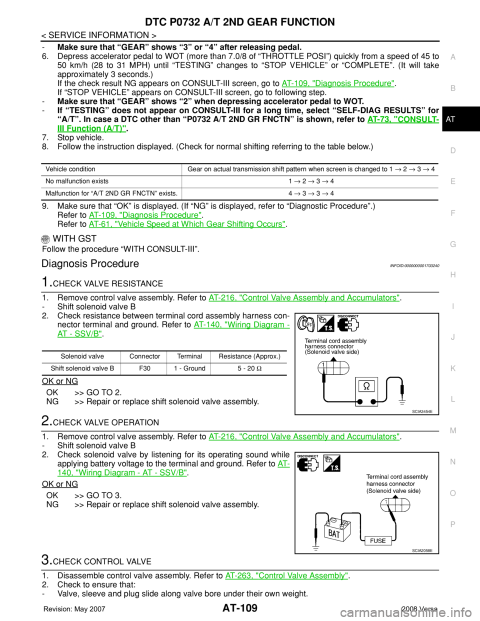
1.CHECK VALVE RESISTANCE
1. Remove control valve assembly. Refer to AT-216, "
Control Valve Assembly and Accumulators".
- Shift solenoid valve B
2. Check resistance between terminal cord assembly harness con-
nector terminal and ground. Refer to AT-140, "
Wiring Diagram -
AT - SSV/B".
OK or NG
OK >> GO TO 2.
NG >> Repair or replace shift solenoid valve assembly.
2.CHECK VALVE OPERATION
1. Remove control valve assembly. Refer to AT-216, "
Control Valve Assembly and Accumulators".
- Shift solenoid valve B
2. Check solenoid valve by listening for its operating sound while
applying battery voltage to the terminal and ground. Refer to AT-
140, "Wiring Diagram - AT - SSV/B".
OK or NG
OK >> GO TO 3.
NG >> Repair or replace shift solenoid valve assembly.
3.CHECK CONTROL VALVE
1. Disassemble control valve assembly. Refer to AT-263, "
Control Valve Assembly".
2. Check to ensure that:
- Valve, sleeve and plug slide along valve bore under their own weight.
Vehicle condition Gear on actual transmission shift pattern when screen is changed to 1 → 2 → 3 → 4
No malfunction exists 1 → 2 → 3 → 4
Malfunction for “A/T 2ND GR FNCTN” exists. 4 → 3 → 3 → 4
Solenoid valve Connector Terminal Resistance (Approx.)
Shift solenoid valve B F30 1 - Ground 5 - 20 Ω
SCIA3454E
SCIA2058E