seat adjustment NISSAN TIIDA 2008 Service User Guide
[x] Cancel search | Manufacturer: NISSAN, Model Year: 2008, Model line: TIIDA, Model: NISSAN TIIDA 2008Pages: 2771, PDF Size: 60.61 MB
Page 2138 of 2771
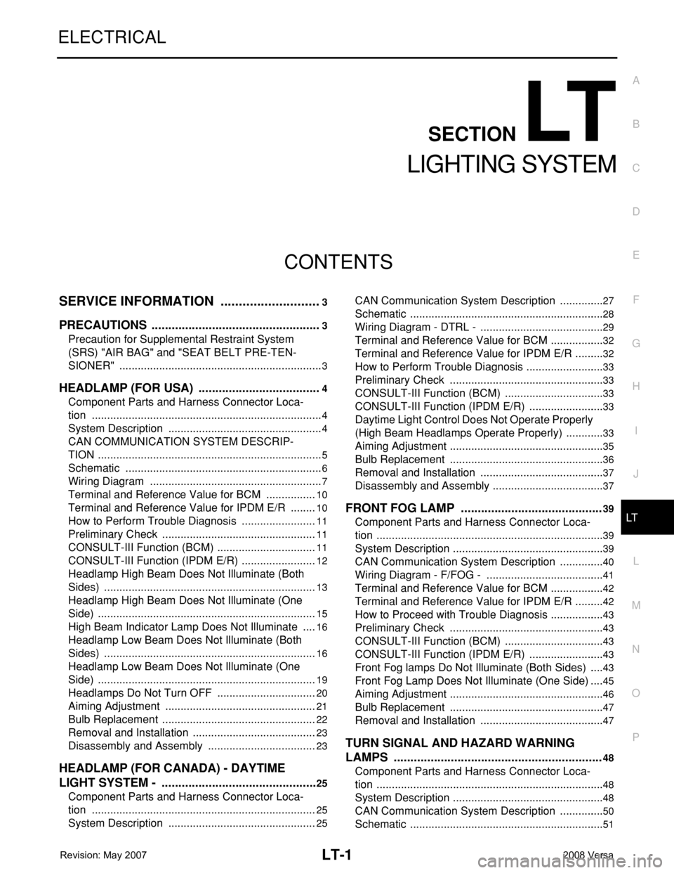
LT-1
ELECTRICAL
C
D
E
F
G
H
I
J
L
M
SECTION LT
A
B
LT
N
O
P
CONTENTS
LIGHTING SYSTEM
SERVICE INFORMATION ............................3
PRECAUTIONS ...................................................3
Precaution for Supplemental Restraint System
(SRS) "AIR BAG" and "SEAT BELT PRE-TEN-
SIONER" ...................................................................
3
HEADLAMP (FOR USA) .....................................4
Component Parts and Harness Connector Loca-
tion ............................................................................
4
System Description ...................................................4
CAN COMMUNICATION SYSTEM DESCRIP-
TION ..........................................................................
5
Schematic .................................................................6
Wiring Diagram .........................................................7
Terminal and Reference Value for BCM .................10
Terminal and Reference Value for IPDM E/R .........10
How to Perform Trouble Diagnosis .........................11
Preliminary Check ...................................................11
CONSULT-III Function (BCM) .................................11
CONSULT-III Function (IPDM E/R) .........................12
Headlamp High Beam Does Not Illuminate (Both
Sides) ......................................................................
13
Headlamp High Beam Does Not Illuminate (One
Side) ........................................................................
15
High Beam Indicator Lamp Does Not Illuminate .....16
Headlamp Low Beam Does Not Illuminate (Both
Sides) ......................................................................
16
Headlamp Low Beam Does Not Illuminate (One
Side) ........................................................................
19
Headlamps Do Not Turn OFF .................................20
Aiming Adjustment ..................................................21
Bulb Replacement ...................................................22
Removal and Installation .........................................23
Disassembly and Assembly ....................................23
HEADLAMP (FOR CANADA) - DAYTIME
LIGHT SYSTEM - ...............................................
25
Component Parts and Harness Connector Loca-
tion ..........................................................................
25
System Description .................................................25
CAN Communication System Description ...............27
Schematic ................................................................28
Wiring Diagram - DTRL - .........................................29
Terminal and Reference Value for BCM ..................32
Terminal and Reference Value for IPDM E/R ..........32
How to Perform Trouble Diagnosis ..........................33
Preliminary Check ...................................................33
CONSULT-III Function (BCM) .................................33
CONSULT-III Function (IPDM E/R) .........................33
Daytime Light Control Does Not Operate Properly
(High Beam Headlamps Operate Properly) .............
33
Aiming Adjustment ...................................................35
Bulb Replacement ...................................................36
Removal and Installation .........................................37
Disassembly and Assembly .....................................37
FRONT FOG LAMP ..........................................39
Component Parts and Harness Connector Loca-
tion ...........................................................................
39
System Description ..................................................39
CAN Communication System Description ...............40
Wiring Diagram - F/FOG - .......................................41
Terminal and Reference Value for BCM ..................42
Terminal and Reference Value for IPDM E/R ..........42
How to Proceed with Trouble Diagnosis ..................43
Preliminary Check ...................................................43
CONSULT-III Function (BCM) .................................43
CONSULT-III Function (IPDM E/R) .........................43
Front Fog lamps Do Not Illuminate (Both Sides) .....43
Front Fog Lamp Does Not Illuminate (One Side) ....45
Aiming Adjustment ...................................................46
Bulb Replacement ...................................................47
Removal and Installation .........................................47
TURN SIGNAL AND HAZARD WARNING
LAMPS ..............................................................
48
Component Parts and Harness Connector Loca-
tion ...........................................................................
48
System Description ..................................................48
CAN Communication System Description ...............50
Schematic ................................................................51
Page 2261 of 2771
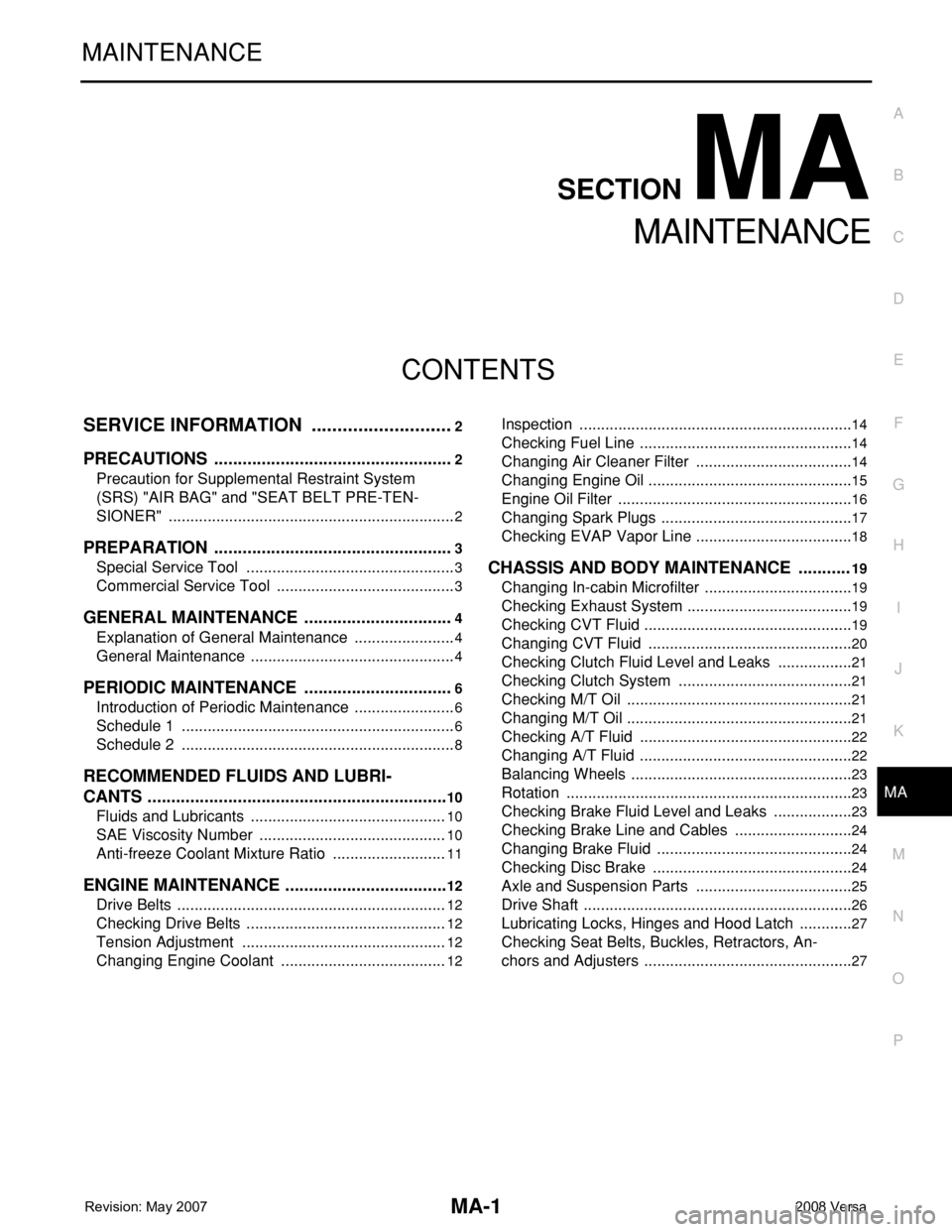
MA-1
MAINTENANCE
C
D
E
F
G
H
I
J
K
M
SECTION MA
A
B
MA
N
O
P
CONTENTS
MAINTENANCE
SERVICE INFORMATION ............................2
PRECAUTIONS ...................................................2
Precaution for Supplemental Restraint System
(SRS) "AIR BAG" and "SEAT BELT PRE-TEN-
SIONER" ...................................................................
2
PREPARATION ...................................................3
Special Service Tool .................................................3
Commercial Service Tool ..........................................3
GENERAL MAINTENANCE ................................4
Explanation of General Maintenance ........................4
General Maintenance ................................................4
PERIODIC MAINTENANCE ................................6
Introduction of Periodic Maintenance ........................6
Schedule 1 ................................................................6
Schedule 2 ................................................................8
RECOMMENDED FLUIDS AND LUBRI-
CANTS ................................................................
10
Fluids and Lubricants ..............................................10
SAE Viscosity Number ............................................10
Anti-freeze Coolant Mixture Ratio ...........................11
ENGINE MAINTENANCE ...................................12
Drive Belts ...............................................................12
Checking Drive Belts ...............................................12
Tension Adjustment ................................................12
Changing Engine Coolant .......................................12
Inspection ................................................................14
Checking Fuel Line ..................................................14
Changing Air Cleaner Filter .....................................14
Changing Engine Oil ................................................15
Engine Oil Filter .......................................................16
Changing Spark Plugs .............................................17
Checking EVAP Vapor Line .....................................18
CHASSIS AND BODY MAINTENANCE ...........19
Changing In-cabin Microfilter ...................................19
Checking Exhaust System .......................................19
Checking CVT Fluid .................................................19
Changing CVT Fluid ................................................20
Checking Clutch Fluid Level and Leaks ..................21
Checking Clutch System .........................................21
Checking M/T Oil .....................................................21
Changing M/T Oil .....................................................21
Checking A/T Fluid ..................................................22
Changing A/T Fluid ..................................................22
Balancing Wheels ....................................................23
Rotation ...................................................................23
Checking Brake Fluid Level and Leaks ...................23
Checking Brake Line and Cables ............................24
Changing Brake Fluid ..............................................24
Checking Disc Brake ...............................................24
Axle and Suspension Parts .....................................25
Drive Shaft ...............................................................26
Lubricating Locks, Hinges and Hood Latch .............27
Checking Seat Belts, Buckles, Retractors, An-
chors and Adjusters .................................................
27
Page 2265 of 2771
GENERAL MAINTENANCE
MA-5
< SERVICE INFORMATION >
C
D
E
F
G
H
I
J
K
MA
B
MA
N
O
P
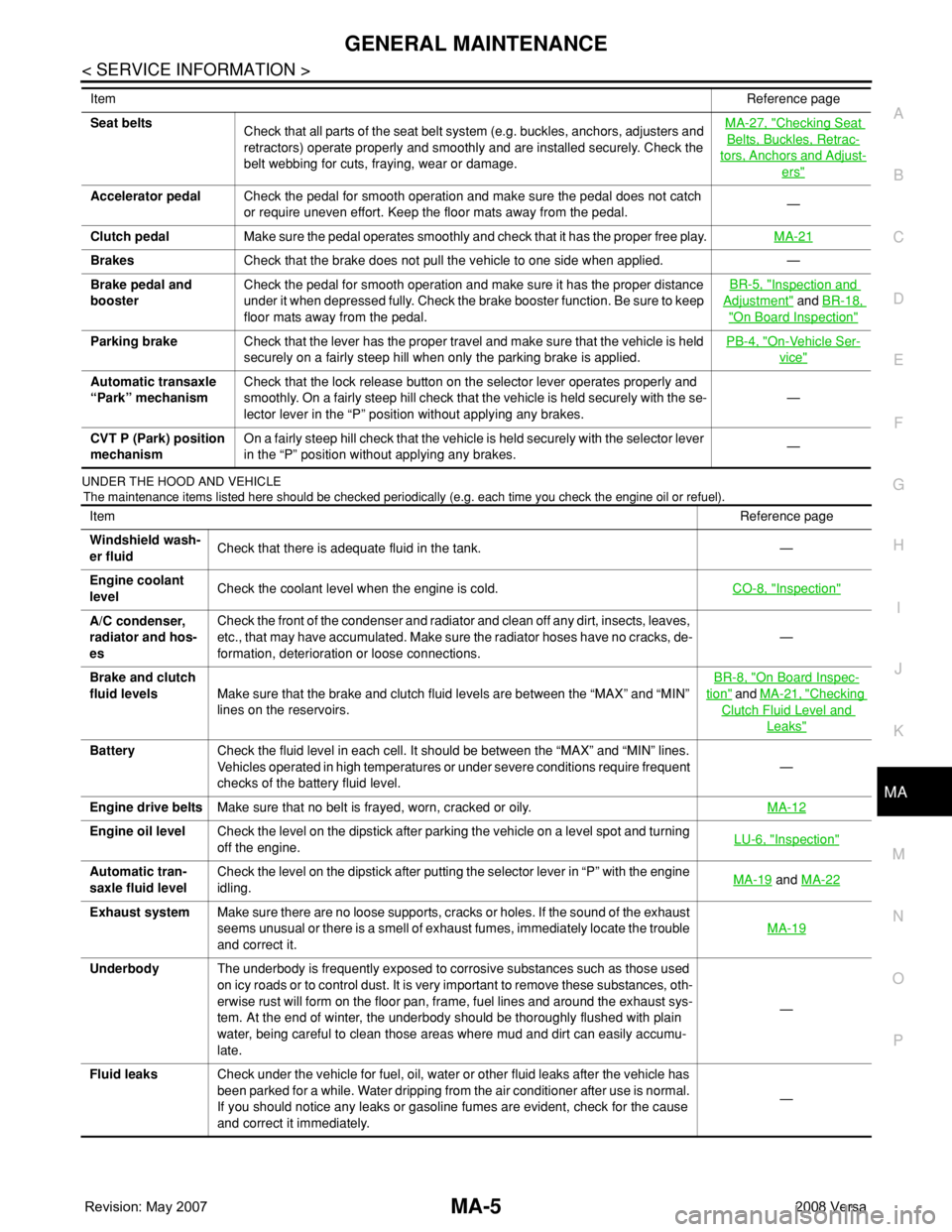
UNDER THE HOOD AND VEHICLE
The maintenance items listed here should be checked periodically (e.g. each time you check the engine oil or refuel).
Seat belts
Check that all parts of the seat belt system (e.g. buckles, anchors, adjusters and
retractors) operate properly and smoothly and are installed securely. Check the
belt webbing for cuts, fraying, wear or damage.MA-27, "Checking Seat
Belts, Buckles, Retrac-
tors, Anchors and Adjust-
ers"
Accelerator pedalCheck the pedal for smooth operation and make sure the pedal does not catch
or require uneven effort. Keep the floor mats away from the pedal.—
Clutch pedalMake sure the pedal operates smoothly and check that it has the proper free play.MA-21
BrakesCheck that the brake does not pull the vehicle to one side when applied. —
Brake pedal and
boosterCheck the pedal for smooth operation and make sure it has the proper distance
under it when depressed fully. Check the brake booster function. Be sure to keep
floor mats away from the pedal.BR-5, "
Inspection and
Adjustment" and BR-18,
"On Board Inspection"
Parking brakeCheck that the lever has the proper travel and make sure that the vehicle is held
securely on a fairly steep hill when only the parking brake is applied.PB-4, "On-Vehicle Ser-
vice"
Automatic transaxle
“Park” mechanismCheck that the lock release button on the selector lever operates properly and
smoothly. On a fairly steep hill check that the vehicle is held securely with the se-
lector lever in the “P” position without applying any brakes.—
CVT P (Park) position
mechanismOn a fairly steep hill check that the vehicle is held securely with the selector lever
in the “P” position without applying any brakes.— ItemReference page
ItemReference page
Windshield wash-
er fluidCheck that there is adequate fluid in the tank. —
Engine coolant
levelCheck the coolant level when the engine is cold.CO-8, "
Inspection"
A/C condenser,
radiator and hos-
esCheck the front of the condenser and radiator and clean off any dirt, insects, leaves,
etc., that may have accumulated. Make sure the radiator hoses have no cracks, de-
formation, deterioration or loose connections.—
Brake and clutch
fluid levelsMake sure that the brake and clutch fluid levels are between the “MAX” and “MIN”
lines on the reservoirs.BR-8, "
On Board Inspec-
tion" and MA-21, "Checking
Clutch Fluid Level and
Leaks"
BatteryCheck the fluid level in each cell. It should be between the “MAX” and “MIN” lines.
Vehicles operated in high temperatures or under severe conditions require frequent
checks of the battery fluid level.—
Engine drive beltsMake sure that no belt is frayed, worn, cracked or oily.MA-12
Engine oil levelCheck the level on the dipstick after parking the vehicle on a level spot and turning
off the engine.LU-6, "Inspection"
Automatic tran-
saxle fluid levelCheck the level on the dipstick after putting the selector lever in “P” with the engine
idling.MA-19 and MA-22
Exhaust systemMake sure there are no loose supports, cracks or holes. If the sound of the exhaust
seems unusual or there is a smell of exhaust fumes, immediately locate the trouble
and correct it.MA-19
UnderbodyThe underbody is frequently exposed to corrosive substances such as those used
on icy roads or to control dust. It is very important to remove these substances, oth-
erwise rust will form on the floor pan, frame, fuel lines and around the exhaust sys-
tem. At the end of winter, the underbody should be thoroughly flushed with plain
water, being careful to clean those areas where mud and dirt can easily accumu-
late.—
Fluid leaksCheck under the vehicle for fuel, oil, water or other fluid leaks after the vehicle has
been parked for a while. Water dripping from the air conditioner after use is normal.
If you should notice any leaks or gasoline fumes are evident, check for the cause
and correct it immediately.—
Page 2339 of 2771
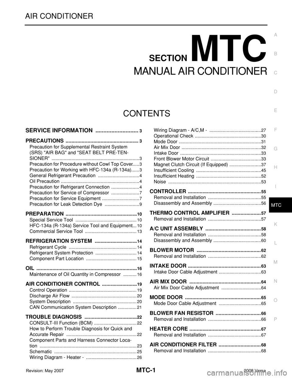
MTC-1
AIR CONDITIONER
C
D
E
F
G
H
I
K
L
M
SECTION MTC
A
B
MTC
N
O
P
CONTENTS
MANUAL AIR CONDITIONER
SERVICE INFORMATION ............................3
PRECAUTIONS ...................................................3
Precaution for Supplemental Restraint System
(SRS) "AIR BAG" and "SEAT BELT PRE-TEN-
SIONER" ...................................................................
3
Precaution for Procedure without Cowl Top Cover ......3
Precaution for Working with HFC-134a (R-134a) ......3
General Refrigerant Precaution ................................4
Oil Precaution ............................................................4
Precaution for Refrigerant Connection ......................4
Precaution for Service of Compressor ......................7
Precaution for Service Equipment .............................7
Precaution for Leak Detection Dye ...........................9
PREPARATION ..................................................10
Special Service Tool ...............................................10
HFC-134a (R-134a) Service Tool and Equipment ....10
Commercial Service Tool ........................................13
REFRIGERATION SYSTEM ..............................14
Refrigerant Cycle ....................................................14
Refrigerant System Protection ................................14
Component Part Location .......................................15
OIL ......................................................................16
Maintenance of Oil Quantity in Compressor ...........16
AIR CONDITIONER CONTROL .........................19
Control Operation ....................................................19
Discharge Air Flow ..................................................20
System Description .................................................20
CAN Communication System Description ...............21
TROUBLE DIAGNOSIS .....................................22
CONSULT-III Function (BCM) .................................22
How to Perform Trouble Diagnosis for Quick and
Accurate Repair ......................................................
22
Component Parts and Harness Connector Loca-
tion ..........................................................................
23
Schematic ...............................................................25
Wiring Diagram - Heater - .......................................26
Wiring Diagram - A/C,M - ........................................27
Operational Check ...................................................30
Mode Door ...............................................................31
Air Mix Door .............................................................32
Intake Door ..............................................................33
Front Blower Motor Circuit .......................................33
Magnet Clutch Circuit (If Equipped) .........................37
Insufficient Cooling ..................................................45
Insufficient Heating ..................................................52
Noise .......................................................................53
CONTROLLER ..................................................55
Removal and Installation .........................................55
Disassembly and Assembly .....................................56
THERMO CONTROL AMPLIFIER ....................57
Removal and Installation .........................................57
A/C UNIT ASSEMBLY ......................................58
Removal and Installation .........................................58
Disassembly and Assembly .....................................60
BLOWER MOTOR ............................................62
Removal and Installation .........................................62
INTAKE DOOR ..................................................63
Intake Door Cable Adjustment .................................63
AIR MIX DOOR .................................................64
Air Mix Door Cable Adjustment ...............................64
MODE DOOR ....................................................65
Mode Door Cable Adjustment .................................65
BLOWER FAN RESISTOR ...............................66
Removal and Installation .........................................66
HEATER CORE .................................................67
Removal and Installation .........................................67
AIR CONDITIONER FILTER .............................68
Removal and Installation .........................................68
Page 2512 of 2771

PS-6
< SERVICE INFORMATION >
STEERING WHEEL
STEERING WHEEL
On-Vehicle Inspection and ServiceINFOID:0000000001703859
CHECKING CONDITION OF INSTALLATION
• Check installation conditions of steering gear assembly, front suspension assembly, axle and steering col-
umn assembly.
• Check if movement exists when steering wheel is moved up and down, to the left and right and to the axial
direction.
• Check steering gear assembly mounting bolts and nuts for looseness. Refer to PS-12, "
Removal and Instal-
lation" .
CHECKING STEERING WHEEL PLAY
• Turn steering wheel so that front wheels come to the straight-ahead position. Start engine and lightly turn
steering wheel to the left and right until front wheels start to move. Measure steering wheel movement on the
outer circumference.
• When the measurement value is outside the standard value, check backlash for each joint of steering col-
umn assembly and installation condition of steering gear assembly.
CHECKING NEUTRAL POSITION STEERING WHEEL
• Make sure that steering gear assembly, steering column assembly and steering wheel are installed in the
correct position.
• Perform neutral position inspection after wheel alignment. Refer to RSU-2, "
Precaution for Supplemental
Restraint System (SRS) "AIR BAG" and "SEAT BELT PRE-TENSIONER"" .
• Set vehicle to the straight-ahead position and confirm steering wheel is in the neutral position.
• Loosen outer socket lock nut and turn inner socket to left and right equally to make fine adjustments if steer-
ing wheel is not in the neutral position.
CHECKING STEERING WHEEL TURNING FORCE
1. Park vehicle on a level and dry surface, set parking brake.
2. Start engine.
3. Check steering wheel turning force when steering wheel has
been turned 360° from neutral position using suitable tool as
shown.
4. If steering wheel turning force is out of the specification, refer to
STC-6, "
How to Perform Trouble Diagnosis" .
CHECKING FRONT WHEEL TURNING ANGLE
Steering wheel axial end play : 0 mm (0 in)
Steering wheel play : 0 - 35 mm (0 - 1.38 in)
Steering wheel
turning force: Less than 36 N (3.7 kg-f, 8.2 lb-f)
WGIA0180E
Page 2531 of 2771

RF-1
BODY
C
D
E
F
G
H
J
K
L
M
SECTION RF
A
B
RF
N
O
P
CONTENTS
ROOF
PRECAUTION ...............................................2
PRECAUTIONS ...................................................2
Precaution for Supplemental Restraint System
(SRS) "AIR BAG" and "SEAT BELT PRE-TEN-
SIONER" ...................................................................
2
Precaution .................................................................2
PREPARATION ............................................3
PREPARATION ...................................................3
Commercial Service Tool ..........................................3
SYMPTOM DIAGNOSIS ...............................4
SQUEAK AND RATTLE TROUBLE DIAG-
NOSES ................................................................
4
Work Flow .................................................................4
Generic Squeak and Rattle Troubleshooting ............6
Diagnostic Worksheet ...............................................8
FUNCTION DIAGNOSIS ..............................10
TROUBLE DIAGNOSIS .....................................10
Component Parts and Harness Connector Loca-
tion ..........................................................................
10
System Description ..................................................10
CAN Communication System Description ...............12
Wiring Diagram - SROOF - ......................................13
Terminal and Reference Value for BCM ..................14
Terminal and Reference Value for Sunroof Motor
Assembly .................................................................
15
Work Flow ................................................................15
CONSULT-III Function (BCM) .................................15
Work Support ...........................................................16
Active Test ...............................................................16
Data Monitor ............................................................16
Trouble Diagnosis Chart by Symptom .....................16
BCM Power Supply and Ground Circuit Inspection
....
16
Sunroof Switch System Inspection ..........................16
Sunroof Motor Assembly Power Supply and
Ground Circuit Inspection ........................................
18
Door Switch Check ..................................................19
ON-VEHICLE REPAIR .................................21
SUNROOF .........................................................21
Removal and Installation .........................................21
Fitting Adjustment ....................................................26
Inspection ................................................................27
Page 2537 of 2771
SQUEAK AND RATTLE TROUBLE DIAGNOSES
RF-7
< SYMPTOM DIAGNOSIS >
C
D
E
F
G
H
J
K
L
MA
B
RF
N
O
P
2. Trunk lid striker out of adjustment
3. The trunk lid torsion bars knocking together
4. A loose license plate or bracket
Most of these incidents can be repaired by adjusting, securing or insulating the item(s) or component(s) caus-
ing the noise.
SUNROOF/HEADLINING
Noises in the sunroof/headlining area can often be traced to one of the following:
1. Sunroof lid, rail, linkage or seals making a rattle or light knocking noise
2. Sun visor shaft shaking in the holder
3. Front or rear windshield touching headliner and squeaking
Again, pressing on the components to stop the noise while duplicating the conditions can isolate most of these
incidents. Repairs usually consist of insulating with felt cloth tape.
OVERHEAD CONSOLE (FRONT AND REAR)
Overhead console noises are often caused by the console panel clips not being engaged correctly. Most of
these incidents are repaired by pushing up on the console at the clip locations until the clips engage.
In addition look for:
1. Loose harness or harness connectors.
2. Front console map/reading lamp lens loose.
3. Loose screws at console attachment points.
SEATS
When isolating seat noise it's important to note the position the seat is in and the load placed on the seat when
the noise is present. These conditions should be duplicated when verifying and isolating the cause of the
noise.
Cause of seat noise include:
1. Headrest rods and holder
2. A squeak between the seat pad cushion and frame
3. The rear seatback lock and bracket
These noises can be isolated by moving or pressing on the suspected components while duplicating the con-
ditions under which the noise occurs. Most of these incidents can be repaired by repositioning the component
or applying urethane tape to the contact area.
UNDERHOOD
Some interior noise may be caused by components under the hood or on the engine wall. The noise is then
transmitted into the passenger compartment.
Causes of transmitted underhood noise include:
1. Any component installed on the engine wall
2. Components that pass through the engine wall
3. Engine wall mounts and connectors
4. Loose radiator pins
5. Hood bumpers out of adjustment
6. Hood striker out of adjustment
These noises can be difficult to isolate since they cannot be reached from the interior of the vehicle. The best
method is to secure, move or insulate one component at a time and test drive the vehicle. Also, engine RPM
or load can be changed to isolate the noise. Repairs can usually be made by moving, adjusting, securing, or
insulating the component causing the noise.
Page 2551 of 2771

SUNROOF
RF-21
< ON-VEHICLE REPAIR >
C
D
E
F
G
H
J
K
L
MA
B
RF
N
O
P
ON-VEHICLE REPAIR
SUNROOF
Removal and InstallationINFOID:0000000001704207
CAUTION:
• After installation or any adjustment, check clearances for sunroof operation and glass lid alignment.
• Handle glass lid with care to prevent damage.
• Fully close the glass lid before removal, then do not operate sunroof motor assembly after removal.
• When removing sunroof unit assembly, use shop cloths to protect the seats and trim from damage.
• Always work with a helper.
NOTE:
For easy installation, mark each point before removal.
Page 2615 of 2771

SQUEAK AND RATTLE TROUBLE DIAGNOSES
SE-7
< SERVICE INFORMATION >
C
D
E
F
G
H
J
K
L
MA
B
SE
N
O
P
Most of these incidents can be repaired by adjusting, securing or insulating the item(s) or component(s) caus-
ing the noise.
SUNROOF/HEADLINING
Noises in the sunroof/headlining area can often be traced to one of the following:
1. Sunroof lid, rail, linkage or seals making a rattle or light knocking noise
2. Sun visor shaft shaking in the holder
3. Front or rear windshield touching headliner and squeaking
Again, pressing on the components to stop the noise while duplicating the conditions can isolate most of these
incidents. Repairs usually consist of insulating with felt cloth tape.
OVERHEAD CONSOLE (FRONT AND REAR)
Overhead console noises are often caused by the console panel clips not being engaged correctly. Most of
these incidents are repaired by pushing up on the console at the clip locations until the clips engage.
In addition look for:
1. Loose harness or harness connectors.
2. Front console map/reading lamp lense loose.
3. Loose screws at console attachment points.
SEATS
When isolating seat noise it's important to note the position the seat is in and the load placed on the seat when
the noise is present. These conditions should be duplicated when verifying and isolating the cause of the
noise.
Cause of seat noise include:
1. Headrest rods and holder
2. A squeak between the seat pad cushion and frame
3. The rear seatback lock and bracket
These noises can be isolated by moving or pressing on the suspected components while duplicating the con-
ditions under which the noise occurs. Most of these incidents can be repaired by repositioning the component
or applying urethane tape to the contact area.
UNDERHOOD
Some interior noise may be caused by components under the hood or on the engine wall. The noise is then
transmitted into the passenger compartment.
Causes of transmitted underhood noise include:
1. Any component mounted to the engine wall
2. Components that pass through the engine wall
3. Engine wall mounts and connectors
4. Loose radiator mounting pins
5. Hood bumpers out of adjustment
6. Hood striker out of adjustment
These noises can be difficult to isolate since they cannot be reached from the interior of the vehicle. The best
method is to secure, move or insulate one component at a time and test drive the vehicle. Also, engine RPM
or load can be changed to isolate the noise. Repairs can usually be made by moving, adjusting, securing, or
insulating the component causing the noise.
Page 2734 of 2771

WW-1
ELECTRICAL
C
D
E
F
G
H
I
J
L
M
SECTION WW
A
B
WW
N
O
P
CONTENTS
WIPER, WASHER & HORN
SERVICE INFORMATION ............................2
PRECAUTION .....................................................2
Precaution for Supplemental Restraint System
(SRS) "AIR BAG" and "SEAT BELT PRE-TEN-
SIONER" ...................................................................
2
Precaution for Procedure without Cowl Top Cover ......2
FRONT WIPER AND WASHER SYSTEM ..........3
Component Parts and Harness Connector Loca-
tion ............................................................................
3
System Description ...................................................3
CAN Communication System Description .................5
Schematic .................................................................6
Wiring Diagram - WIPER - ........................................7
Terminal and Reference Value for BCM ...................9
Terminal and Reference Value for IPDM E/R ...........9
How to Proceed with Trouble Diagnosis .................10
Preliminary Check ...................................................10
CONSULT-III Function (BCM) .................................10
CONSULT-III Function (IPDM E/R) .........................11
Front Wiper Does Not Operate ...............................12
Front Wiper Does Not Return to Stop Position (Af-
ter Front Wiper Operate for 10 Seconds, They
Stop for 20 Seconds, and After Repeating the Op-
eration Five Times, They Become Inoperative) ......
14
Only Front Wiper Low Does Not Operate ...............15
Only Front Wiper High Does Not Operate ...............16
Only Front Wiper Intermittent Does Not Operate ....17
Front Wiper Intermittent Operation Switch Posi-
tion Cannot Be Adjusted .........................................
17
Wiper Does Not Wipe When Front Washer Oper-
ates .........................................................................
18
Front Wiper Does Not Stop .....................................18
Removal and Installation of Front Wiper Arms ........18
Adjustment of Wiper Arm Stop Location .................19
Removal and Installation of Front Wiper Drive As-
sembly .....................................................................
19
Removal and Installation of Front Washer Nozzle ....20
Inspection for Washer Nozzle ..................................20
Washer Nozzle Adjustment .....................................21
Washer Tube Layout ...............................................21
Removal and Installation of Front Wiper and
Washer Switch .........................................................
22
Inspection of Front Wiper and Washer Switch Cir-
cuit ...........................................................................
22
Removal and Installation of Washer Tank ...............22
Removal and Installation of Front Washer Motor ....23
REAR WIPER AND WASHER SYSTEM ..........24
Component Parts and Harness Connector Loca-
tion ...........................................................................
24
System Description ..................................................24
Wiring Diagram - WIP/R - ........................................26
Terminal and Reference Value for BCM ..................27
How to Proceed with Trouble Diagnosis ..................27
Preliminary Check ...................................................28
CONSULT-III Function (BCM) .................................28
Rear Wiper Does Not Operate ................................28
Rear Wiper Stop Position Is Incorrect .....................29
Only Rear Wiper Does Not Operate ........................30
Only Rear Wiper Intermittent Does Not Operate .....31
Wiper Does Not Wipe When Rear Washer Oper-
ates ..........................................................................
31
Removal and Installation .........................................31
Washer Nozzle Adjustment .....................................34
POWER SOCKET .............................................35
Wiring Diagram - P/SCKT - .....................................35
Removal and Installation .........................................35
HORN ................................................................37
Wiring Diagram - HORN - ........................................37
Removal and Installation .........................................37