oil pressure NISSAN TIIDA 2008 Service Repair Manual
[x] Cancel search | Manufacturer: NISSAN, Model Year: 2008, Model line: TIIDA, Model: NISSAN TIIDA 2008Pages: 2771, PDF Size: 60.61 MB
Page 4 of 2771

2008
QUICK REFERENCE CHART: VERSA
QUICK REFERENCE CHART: VERSA
Engine Tune-up DataINFOID:0000000001903528
GENERAL SPECIFICATIONS
SPARK PLUG
Unit: mm (in)
Front Wheel Alignment (Unladen*)INFOID:0000000001903529
Engine typeMR18DE
Cylinder arrangement In-line 4
Displacement cm
3 (cu in)1,797 (109.65)
Bore and stroke mm (in) 84.0 x 81.1 (3.307 x 3.192)
Valve arrangement DOHC
Firing order 1-3-4-2
Number of piston rings Compression 2
Oil 1
Compression ratio 9.9
Compression pressure
kPa (bar, kg/cm
2 , psi) / 250 rpm Standard 1,500 (15.0, 15.3, 217.6)
Minimum 1,200 (12.0, 12.2, 174)
Differential limit between cylinders 100 (1.0, 1.0, 15)
Plug type
Iridium-tipped TYPE
Make DENSO
Standard type FXE20HR11
Spark plug gap Nominal: 1.1 (0.043)
Camber
Degree minute (Decimal degree)RH
Minimum - 1
° 05 ′ (- 1.08 °)
Nominal - 0 ° 20 ′ (- 0.33 °)
Maximum 0 ° 25 ′ (0.42 °)
LH Minimum - 0
° 55 ′ (- 0.92 °)
Nominal - 0 ° 10 ′ (- 0.17 °)
Maximum 0 ° 35 ′ (0.58 °)
Left and right difference
(RH - LH) Minimum -0
° 45 ′ (-0.75 °) or less
Nominal -0 ° 12 ′ (-0.20 °) or less
Maximum 0 ° 21 ′ (0.35 °) or less
Caster
Degree minute (Decimal degree) RH
Minimum 4
° 05 ′ (4.08 °)
Nominal 4 ° 50 ′ (4.83 °)
Maximum 5 ° 35 ′ (5.58 °)
LH Minimum 3
° 55 ′ (3.92 °)
Nominal 4 ° 40 ′ (4.67 °)
Maximum 5 ° 25 ′ (5.42 °)
Left and right difference
(RH - LH) Minimum -0
° 21 ′ (-0.35 °) or less
Nominal 0 ° 12 ′ (0.20 °) or less
Maximum 0 ° 45 ′ (0.75 °) or less
Page 16 of 2771

AT-4
Diagnosis Procedure .............................................210
KEY INTERLOCK CABLE ...............................213
Removal and Installation .......................................213
ON-VEHICLE SERVICE ..................................216
Control Valve Assembly and Accumulators ...........216
Park/Neutral Position (PNP) Switch ......................219
Revolution Sensor .................................................221
Turbine Revolution Sensor (Power Train Revolu-
tion Sensor) ...........................................................
222
Differential Side Oil Seal ........................................223
AIR BREATHER HOSE ...................................225
Removal and Installation .......................................225
TRANSAXLE ASSEMBLY ..............................226
Removal and Installation .......................................226
OVERHAUL .....................................................230
Component ............................................................230
Oil Channel ............................................................237
Location of Adjusting Shims, Needle Bearings and
Thrust Washers .....................................................
238
Location of Snap Rings .........................................239
DISASSEMBLY ...............................................240
Disassembly ..........................................................240
REPAIR FOR COMPONENT PARTS ..............257
Manual Shaft .........................................................257
Oil Pump ................................................................260
Control Valve Assembly ........................................263
Control Valve Upper Body .....................................272
Control Valve Lower Body .....................................276
Reverse Clutch ......................................................279
High Clutch ............................................................284
Forward and Overrun Clutches .............................288
Low & Reverse Brake ............................................295
Rear Internal Gear and Forward Clutch Hub .........299
Output Shaft, Output Gear, Idler Gear, Reduction
Pinion Gear and Bearing Retainer .........................
302
Band Servo Piston Assembly ................................307
Final Drive .............................................................313
ASSEMBLY ......................................................318
Assembly (1) .........................................................318
Adjustment (1) .......................................................319
Assembly (2) .........................................................325
Adjustment (2) .......................................................330
Assembly (3) .........................................................333
SERVICE DATA AND SPECIFICATIONS
(SDS) ................................................................
341
General Specification ............................................341
Vehicle Speed at Which Gear Shifting Occurs .....341
Vehicle Speed at When Lock-up Occurs/Releases
.
341
Stall Speed ............................................................341
Line Pressure ........................................................341
Adjusting shims, Needle Bearings, Thrust Wash-
ers and Snap Rings ..............................................
341
Control Valves .......................................................343
Accumulator ..........................................................343
Clutches and Brakes .............................................343
Final Drive .............................................................345
Planetary Carrier ...................................................345
Oil Pump ...............................................................345
Input Shaft .............................................................345
Reduction Pinion Gear ..........................................345
Band Servo ...........................................................345
Output Shaft ..........................................................346
Bearing Retainer ...................................................346
Total End Play .......................................................346
Reverse Clutch End Play ......................................346
Removal and Installation .......................................346
Shift Solenoid Valves ............................................346
Solenoid Valves ....................................................346
A/T Fluid Temperature Sensor ..............................347
Revolution Sensor .................................................347
Dropping Resistor .................................................347
Turbine Revolution Sensor (Power Train Revolu-
tion Sensor) ...........................................................
347
Page 22 of 2771
AT-10
< SERVICE INFORMATION >
PREPARATION
PREPARATION
Special Service ToolINFOID:0000000001703156
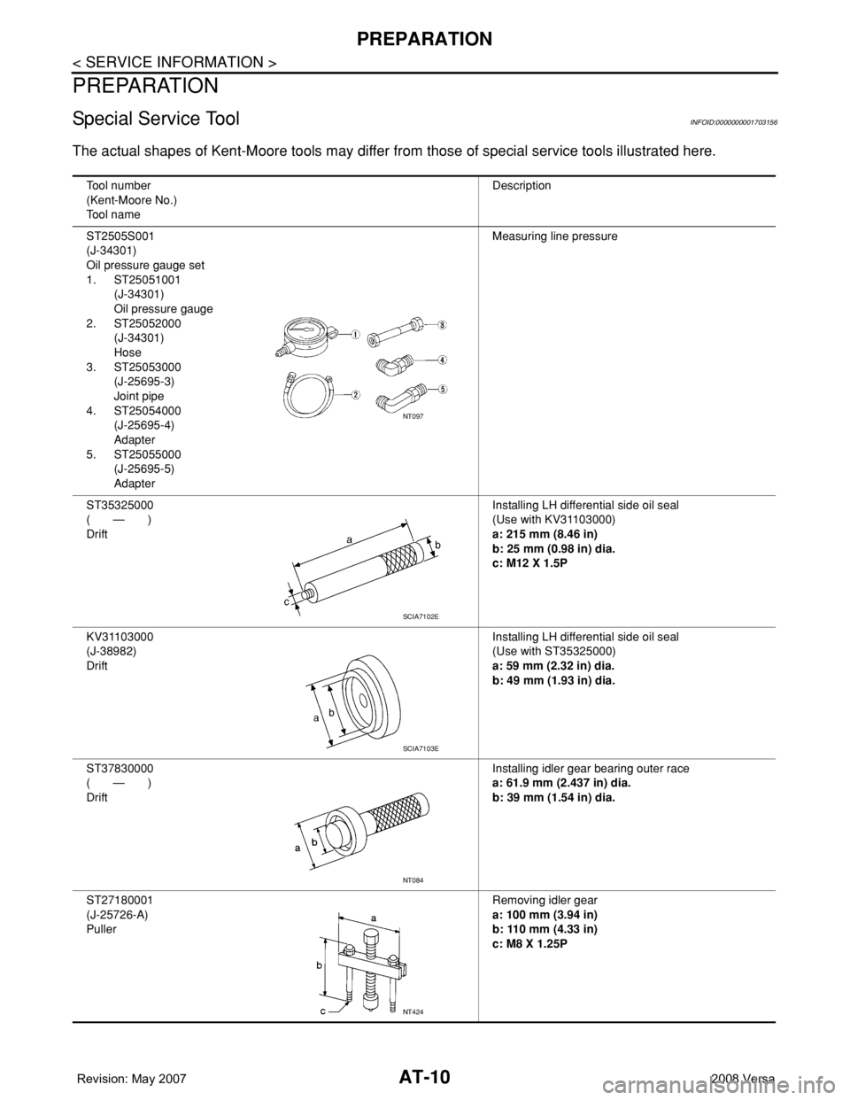
The actual shapes of Kent-Moore tools may differ from those of special service tools illustrated here.
Tool number
(Kent-Moore No.)
Tool nameDescription
ST2505S001
(J-34301)
Oil pressure gauge set
1. ST25051001
(J-34301)
Oil pressure gauge
2. ST25052000
(J-34301)
Hose
3. ST25053000
(J-25695-3)
Joint pipe
4. ST25054000
(J-25695-4)
Adapter
5. ST25055000
(J-25695-5)
AdapterMeasuring line pressure
ST35325000
( — )
DriftInstalling LH differential side oil seal
(Use with KV31103000)
a: 215 mm (8.46 in)
b: 25 mm (0.98 in) dia.
c: M12 X 1.5P
KV31103000
(J-38982)
DriftInstalling LH differential side oil seal
(Use with ST35325000)
a: 59 mm (2.32 in) dia.
b: 49 mm (1.93 in) dia.
ST37830000
( — )
DriftInstalling idler gear bearing outer race
a: 61.9 mm (2.437 in) dia.
b: 39 mm (1.54 in) dia.
ST27180001
(J-25726-A)
PullerRemoving idler gear
a: 100 mm (3.94 in)
b: 110 mm (4.33 in)
c: M8 X 1.25P
NT097
SCIA7102E
SCIA7103E
NT084
NT424
Page 33 of 2771
A/T CONTROL SYSTEM
AT-21
< SERVICE INFORMATION >
D
E
F
G
H
I
J
K
L
MA
B
AT
N
O
P
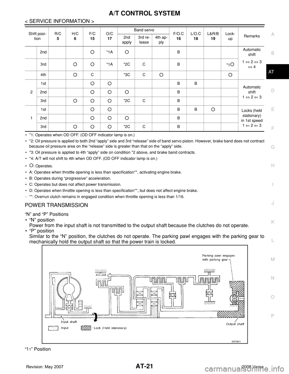
• *1: Operates when OD OFF. (OD OFF indicator lamp is on.)
• *2: Oil pressure is applied to both 2nd “apply” side and 3rd “release” side of band servo piston. However, brake band does not contract
because oil pressure area on the “release” side is greater than that on the “apply” side.
• *3: Oil pressure is applied to 4th “apply” side on condition *2 above, and brake band contracts.
• *4: A/T will not shift to 4th when OD OFF. (OD OFF indicator lamp is on.)
• : Operates.
• A: Operates when throttle opening is less than specification**, activating engine brake.
• B: Operates during “progressive” acceleration.
• C: Operates but does not affect power transmission.
• D: Operates when throttle opening is less than specification**, but does not affect engine brake.
- **: Overrun clutch remains in engaged condition when throttle opening is less than 1/16.
POWER TRANSMISSION
“N” and “P” Positions
• “N” position
Power from the input shaft is not transmitted to the output shaft because the clutches do not operate.
• “P” position
Similar to the “N” position, the clutches do not operate. The parking pawl engages with the parking gear to
mechanically hold the output shaft so that the power train is locked.
“11” Position
2nd *1A BAutomatic
shift
3rd *1A *2C C B
*11 ⇔ 2 ⇔ 3
⇔ 4
4th C *3C C
21stBB
Automatic
shift
1 ⇔ 2 ⇐ 3 2ndB
3rd *2C C B
11stBB
Locks (held
stationary)
in 1st speed
1 ⇐ 2 ⇐ 3 2ndB
3rd *2C C B Shift posi-
tionR/C
5H/C
6F/C
15O/C
17Band servo
F/O.C
16L/O.C
18L&R/B
19Lock-
upRemarks
2nd
apply3rd re-
lease4th ap-
ply
SAT991I
Page 43 of 2771
A/T CONTROL SYSTEM
AT-31
< SERVICE INFORMATION >
D
E
F
G
H
I
J
K
L
MA
B
AT
N
O
P
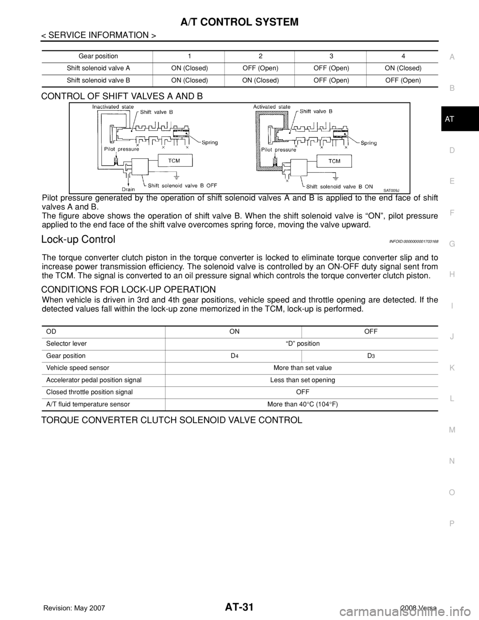
CONTROL OF SHIFT VALVES A AND B
Pilot pressure generated by the operation of shift solenoid valves A and B is applied to the end face of shift
valves A and B.
The figure above shows the operation of shift valve B. When the shift solenoid valve is “ON”, pilot pressure
applied to the end face of the shift valve overcomes spring force, moving the valve upward.
Lock-up ControlINFOID:0000000001703168
The torque converter clutch piston in the torque converter is locked to eliminate torque converter slip and to
increase power transmission efficiency. The solenoid valve is controlled by an ON-OFF duty signal sent from
the TCM. The signal is converted to an oil pressure signal which controls the torque converter clutch piston.
CONDITIONS FOR LOCK-UP OPERATION
When vehicle is driven in 3rd and 4th gear positions, vehicle speed and throttle opening are detected. If the
detected values fall within the lock-up zone memorized in the TCM, lock-up is performed.
TORQUE CONVERTER CLUTCH SOLENOID VALVE CONTROL
Gear position 1 2 3 4
Shift solenoid valve A ON (Closed) OFF (Open) OFF (Open) ON (Closed)
Shift solenoid valve B ON (Closed) ON (Closed) OFF (Open) OFF (Open)
SAT009J
OD ON OFF
Selector lever “D” position
Gear position D
4D3
Vehicle speed sensor More than set value
Accelerator pedal position signal Less than set opening
Closed throttle position signal OFF
A/T fluid temperature sensor More than 40°C (104°F)
Page 46 of 2771

AT-34
< SERVICE INFORMATION >
A/T CONTROL SYSTEM
Control Valve
INFOID:0000000001703170
FUNCTION OF CONTROL VALVES
Centrifugal Cancel MechanismINFOID:0000000001703171
FUNCTION
The centrifugal cancel mechanism is a mechanism to cancel the centrifugal hydraulic pressure instead of the
conventional check balls. It cancels the centrifugal hydraulic pressure which is generated as high clutch drum
rotates, and it allows for preventing high clutch from dragging and for providing stable high clutch piston press-
ing force in all revolution speeds.
STRUCTURE/OPERATION
Valve name Function
Pressure regulator valve, plug and sleeve
plugRegulates oil discharged from the oil pump to provide optimum line pressure for all driving
conditions.
Pressure modifier valve and sleeve Used as a signal supplementary valve to the pressure regulator valve. Regulates pres-
sure-modifier pressure (signal pressure) which controls optimum line pressure for all driv-
ing conditions.
Pilot valve Regulates line pressure to maintain a constant pilot pressure level which controls lock-up
mechanism, overrun clutch, shift timing.
Accumulator control valve Regulates accumulator back-pressure to pressure suited to driving conditions.
Manual valve Directs line pressure to oil circuits corresponding to select positions.
Hydraulic pressure drains when the shift lever is in Neutral.
Shift valve A Simultaneously switches three oil circuits using output pressure of shift solenoid valve A
to meet driving conditions (vehicle speed, throttle opening, etc.).
Provides automatic downshifting and upshifting (1st → 2nd → 3rd → 4th gears/4th → 3rd
→ 2nd → 1st gears) in combination with shift valve B.
Shift valve B Simultaneously switches two oil circuits using output pressure of shift solenoid valve B in
relation to driving conditions (vehicle speed, throttle opening, etc.).
Provides automatic downshifting and upshifting (1st → 2nd → 3rd → 4th gears/4th → 3rd
→ 2nd → 1st gears) in combination with shift valve A.
Overrun clutch control valve Switches hydraulic circuits to prevent engagement of the overrun clutch simultaneously
with application of the brake band in D
4. (Interlocking occurs if the overrun clutch engages
during D
4.)
1st reducing valve Reduces low & reverse brake pressure to dampen engine-brake shock when downshift-
ing from the 1st position 1
2 to 11.
Overrun clutch reducing valve Reduces oil pressure directed to the overrun clutch and prevents engine-brake shock.
In the 1st and 2nd positions, line pressure acts on the overrun clutch reducing valve to
increase the pressure-regulating point, with resultant engine brake capability.
Torque converter relief valve Prevents an excessive rise in torque converter pressure.
Torque converter clutch control valve, plug
and sleeveActivates or inactivates the lock-up function.
Also provides smooth lock-up through transient application and release of the lock-up
system.
1-2 accumulator valve and piston Lessens the shock find when the 2nd gear band servo contracts, and provides smooth
shifting.
3-2 timing valve Switches the pace that oil pressure is released depending on vehicle speed; maximizes
the high clutch release timing, and allows for soft downshifting.
Shuttle valve Determines if the overrun clutch solenoid valve should control the 3-2 timing valve or the
overrun clutch control valve and switches between the two.
Cooler check valve At low speeds and with a small load when a little heat is generated, saves the volume of
cooler flow, and stores the oil pressure for lock-up.
Page 47 of 2771
A/T CONTROL SYSTEM
AT-35
< SERVICE INFORMATION >
D
E
F
G
H
I
J
K
L
MA
B
AT
N
O
P
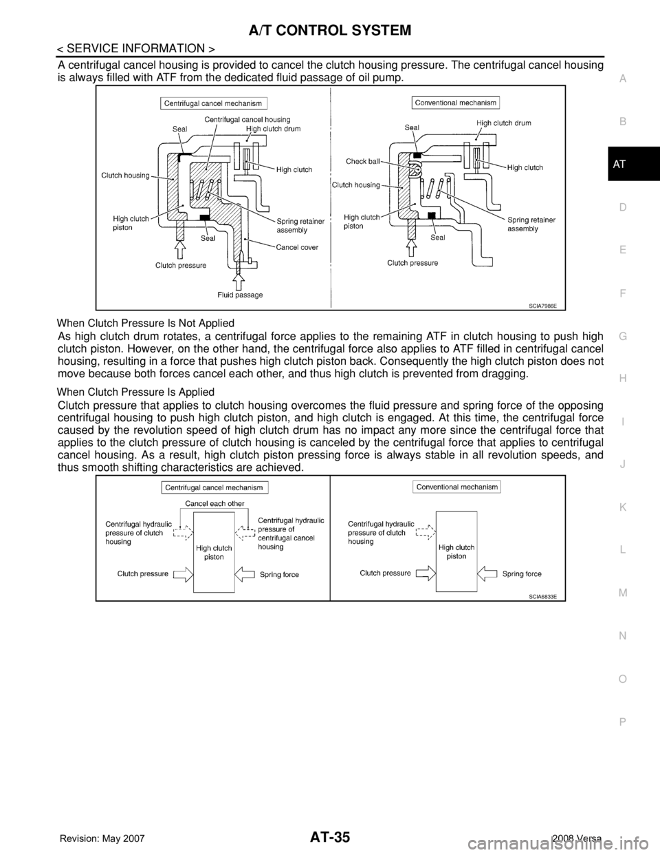
A centrifugal cancel housing is provided to cancel the clutch housing pressure. The centrifugal cancel housing
is always filled with ATF from the dedicated fluid passage of oil pump.
When Clutch Pressure Is Not Applied
As high clutch drum rotates, a centrifugal force applies to the remaining ATF in clutch housing to push high
clutch piston. However, on the other hand, the centrifugal force also applies to ATF filled in centrifugal cancel
housing, resulting in a force that pushes high clutch piston back. Consequently the high clutch piston does not
move because both forces cancel each other, and thus high clutch is prevented from dragging.
When Clutch Pressure Is Applied
Clutch pressure that applies to clutch housing overcomes the fluid pressure and spring force of the opposing
centrifugal housing to push high clutch piston, and high clutch is engaged. At this time, the centrifugal force
caused by the revolution speed of high clutch drum has no impact any more since the centrifugal force that
applies to the clutch pressure of clutch housing is canceled by the centrifugal force that applies to centrifugal
cancel housing. As a result, high clutch piston pressing force is always stable in all revolution speeds, and
thus smooth shifting characteristics are achieved.
SCIA7986E
SCIA6833E
Page 52 of 2771
AT-40
< SERVICE INFORMATION >
TROUBLE DIAGNOSIS
●: Solenoid ON
×: Solenoid OFF
–: Non-standard condition
Line Pressure Solenoid Valve
If non-standard solenoid signal is sent to TCM, line pressure solenoid valve is turned OFF to achieve maxi-
mum oil pressure.
Torque Converter Clutch Solenoid Valve
If non-standard solenoid signal is sent to TCM, torque converter clutch solenoid valve is turned OFF to release
lock-up.
Overrun Clutch Solenoid Valve
If non-standard solenoid signal is sent to TCM, overrun clutch solenoid valve is turned OFF to engage overrun
clutch. This will result in more effective engine brake during deceleration.
How to Perform Trouble Diagnosis for Quick and Accurate RepairINFOID:0000000001703179
INTRODUCTION
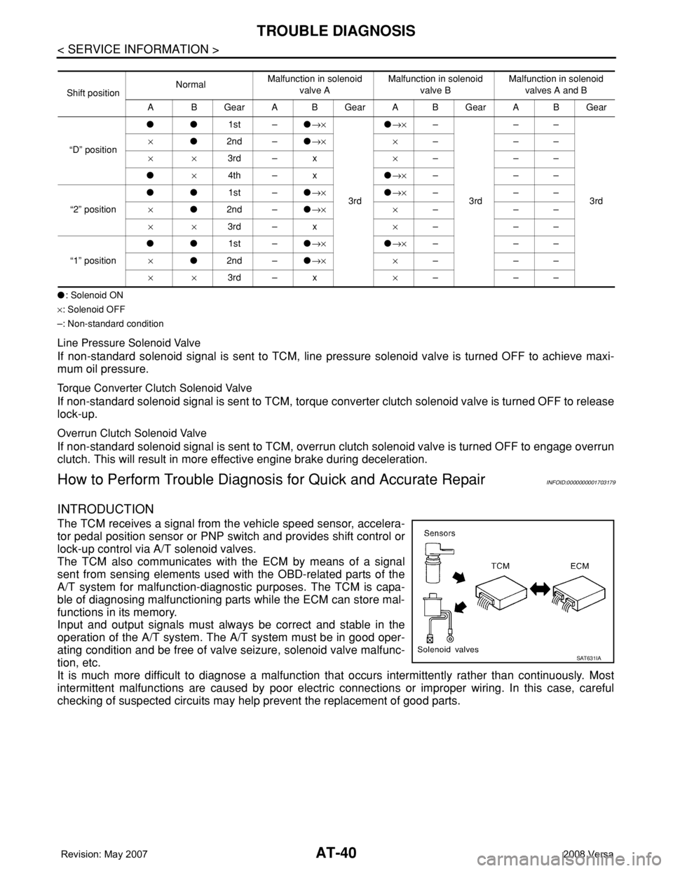
The TCM receives a signal from the vehicle speed sensor, accelera-
tor pedal position sensor or PNP switch and provides shift control or
lock-up control via A/T solenoid valves.
The TCM also communicates with the ECM by means of a signal
sent from sensing elements used with the OBD-related parts of the
A/T system for malfunction-diagnostic purposes. The TCM is capa-
ble of diagnosing malfunctioning parts while the ECM can store mal-
functions in its memory.
Input and output signals must always be correct and stable in the
operation of the A/T system. The A/T system must be in good oper-
ating condition and be free of valve seizure, solenoid valve malfunc-
tion, etc.
It is much more difficult to diagnose a malfunction that occurs intermittently rather than continuously. Most
intermittent malfunctions are caused by poor electric connections or improper wiring. In this case, careful
checking of suspected circuits may help prevent the replacement of good parts.
Shift positionNormalMalfunction in solenoid
valve AMalfunction in solenoid
valve BMalfunction in solenoid
valves A and B
A B Gear A B Gear A B Gear A B Gear
“D” position●●1st –●→×
3rd ●→×–
3rd ––
3rd ×●2nd –●→× ×–––
××3rd – x×–––
●×4th – x●→×–––
“2” position●●1st –●→×●→×–––
×●2nd –●→× ×–––
××3rd – x×–––
“1” position●●1st –●→×●→×–––
×●2nd –●→× ×–––
××3rd – x×–––
SAT631IA
Page 63 of 2771
TROUBLE DIAGNOSIS
AT-51
< SERVICE INFORMATION >
D
E
F
G
H
I
J
K
L
MA
B
AT
N
O
P
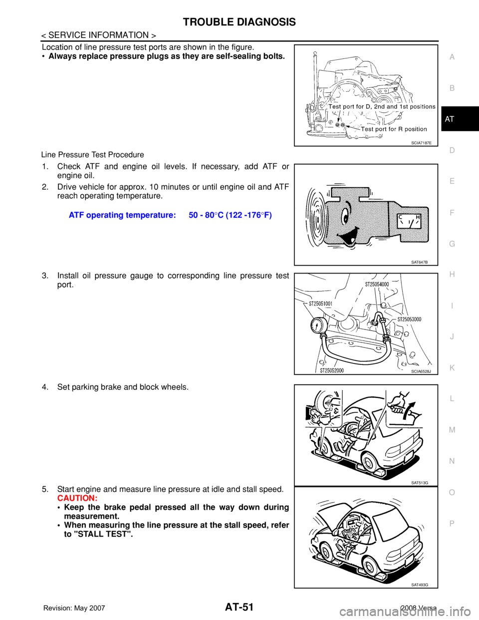
Location of line pressure test ports are shown in the figure.
•Always replace pressure plugs as they are self-sealing bolts.
Line Pressure Test Procedure
1. Check ATF and engine oil levels. If necessary, add ATF or
engine oil.
2. Drive vehicle for approx. 10 minutes or until engine oil and ATF
reach operating temperature.
3. Install oil pressure gauge to corresponding line pressure test
port.
4. Set parking brake and block wheels.
5. Start engine and measure line pressure at idle and stall speed.
CAUTION:
• Keep the brake pedal pressed all the way down during
measurement.
• When measuring the line pressure at the stall speed, refer
to "STALL TEST".
SCIA7187E
ATF operating temperature: 50 - 80°C (122 -176°F)
SAT647B
SCIA6528J
SAT513G
SAT493G
Page 64 of 2771
AT-52
< SERVICE INFORMATION >
TROUBLE DIAGNOSIS
Line Pressure
Judgement of Line Pressure Test
Road TestINFOID:0000000001703183
DESCRIPTION
• The purpose of the test is to determine overall performance of A/T
and analyze causes of malfunctions.
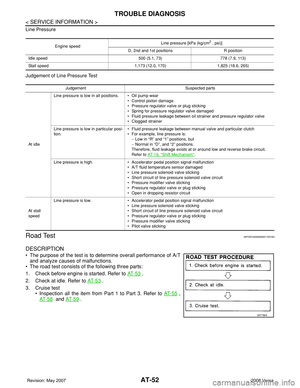
• The road test consists of the following three parts:
1. Check before engine is started. Refer to AT- 5 3
.
2. Check at idle. Refer to AT- 5 3
.
3. Cruise test
• Inspection all the item from Part 1 to Part 3. Refer to AT- 5 5
,
AT- 5 8
and AT- 5 9 .
Engine speedLine pressure [kPa (kg/cm
2 , psi)]
D, 2nd and 1st positions R position
Idle speed 500 (5.1, 73) 778 (7.9, 113)
Stall speed 1,173 (12.0, 170) 1,825 (18.6, 265)
Judgement Suspected parts
At idleLine pressure is low in all positions. • Oil pump wear
• Control piston damage
• Pressure regulator valve or plug sticking
• Spring for pressure regulator valve damaged
• Fluid pressure leakage between oil strainer and pressure regulator valve
• Clogged strainer
Line pressure is low in particular posi-
tion.• Fluid pressure leakage between manual valve and particular clutch
• For example, line pressure is:
− Low in “R” and “1” positions, but
− Normal in “D”, and “2” positions.
Therefore, fluid leakage exists at or around low and reverse brake circuit.
Refer to AT- 1 9 , "
Shift Mechanism".
Line pressure is high. • Accelerator pedal position signal malfunction
• A/T fluid temperature sensor damaged
• Line pressure solenoid valve sticking
• Short circuit of line pressure solenoid valve circuit
• Pressure modifier valve sticking
• Pressure regulator valve or plug sticking
• Open in dropping resistor circuit
At stall
speedLine pressure is low. • Accelerator pedal position signal malfunction
• Line pressure solenoid valve sticking
• Short circuit of line pressure solenoid valve circuit
• Pressure regulator valve or plug sticking
• Pressure modifier valve sticking
• Pilot valve sticking
SAT786A