wheels NISSAN TIIDA 2008 Service User Guide
[x] Cancel search | Manufacturer: NISSAN, Model Year: 2008, Model line: TIIDA, Model: NISSAN TIIDA 2008Pages: 2771, PDF Size: 60.61 MB
Page 1388 of 2771
EC-314
< SERVICE INFORMATION >
DTC P0441 EVAP CONTROL SYSTEM
1. Start engine and warm it up to normal operating temperature.
2. Turn ignition switch OFF and wait at least 10 seconds.
3. Start engine and let it idle for at least 70 seconds.
4. Select “PURG FLOW P0441” of “EVAPORATIVE SYSTEM” in “DTC CONFIRMATION” mode with CON-
SULT-II.
5. Touch “START”.
If “COMPLETED” is displayed, go to step 7.
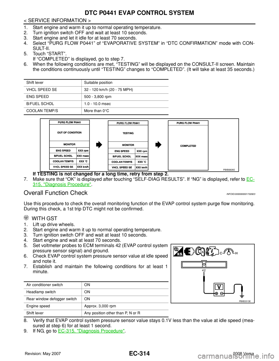
6. When the following conditions are met, “TESTING” will be displayed on the CONSULT-II screen. Maintain
the conditions continuously until “TESTING” changes to “COMPLETED”. (It will take at least 35 seconds.)
If TESTING is not changed for a long time, retry from step 2.
7. Make sure that “OK” is displayed after touching “SELF-DIAG RESULTS”. If “NG” is displayed, refer to EC-
315, "Diagnosis Procedure".
Overall Function CheckINFOID:0000000001702823
Use this procedure to check the overall monitoring function of the EVAP control system purge flow monitoring.
During this check, a 1st trip DTC might not be confirmed.
WITH GST
1. Lift up drive wheels.
2. Start engine and warm it up to normal operating temperature.
3. Turn ignition switch OFF and wait at least 10 seconds.
4. Start engine and wait at least 70 seconds.
5. Set voltmeter probes to ECM terminals 42 (EVAP control system
pressure sensor signal) and ground.
6. Check EVAP control system pressure sensor value at idle speed
and note it.
7. Establish and maintain the following conditions for at least 1
minute.
8. Verify that EVAP control system pressure sensor value stays 0.1V less than the value at idle speed (mea-
sured at step 6) for at least 1 second.
9. If NG, go to EC-315, "
Diagnosis Procedure".
Shift lever Suitable position
VHCL SPEED SE 32 - 120 km/h (20 - 75 MPH)
ENG SPEED 500 - 3,800 rpm
B/FUEL SCHDL 1.0 - 10.0 msec
COOLAN TEMP/S More than 0°C
PBIB0826E
Air conditioner switch ON
Headlamp switch ON
Rear window defogger switch ON
Engine speed Approx. 3,000 rpm
Shift lever Any position other than P, N or R
PBIB3313E
Page 1465 of 2771
DTC P0500 VSS
EC-391
< SERVICE INFORMATION >
C
D
E
F
G
H
I
J
K
L
MA
EC
N
P O
DTC P0500 VSS
DescriptionINFOID:0000000001702900
NOTE:
•If DTC P0500 is displayed with DTC U1000 or U1001, first perform the trouble diagnosis for DTC
U1000, U1001. Refer to EC-143
.
•If DTC P0500 is displayed with DTC U1010, first perform the trouble diagnosis for DTC U1010. Refer
to EC-145
.
The vehicle speed signal is sent to the combination meter from “ABS actuator and electric unit (control unit)”
through CAN communication line. The combination meter then sends a signal to the ECM through CAN com-
munication line.
On Board Diagnosis LogicINFOID:0000000001702901
FAIL-SAFE MODE
When the malfunction is detected, ECM enters fail-safe mode.
DTC Confirmation ProcedureINFOID:0000000001702902
CAUTION:
Always drive vehicle at a safe speed.
NOTE:
If DTC Confirmation Procedure has been previously conducted, always turn ignition switch OFF and wait at
least 10 seconds before conducting the next test.
TESTING CONDITION:
Steps 1 and 2 may be conducted with the drive wheels lifted in the shop or by driving the vehicle. If a
road test is expected to be easier, it is unnecessary to lift the vehicle.
WITH CONSULT-II
1. Start engine.
2. Read “VHCL SPEED SE” in “DATA MONITOR” mode with CONSULT-II. The vehicle speed on CONSULT-
II should exceed 10 km/h (6 MPH) when rotating wheels with suitable gear position.
If NG, go to EC-392, "
Diagnosis Procedure".
If OK, go to following step.
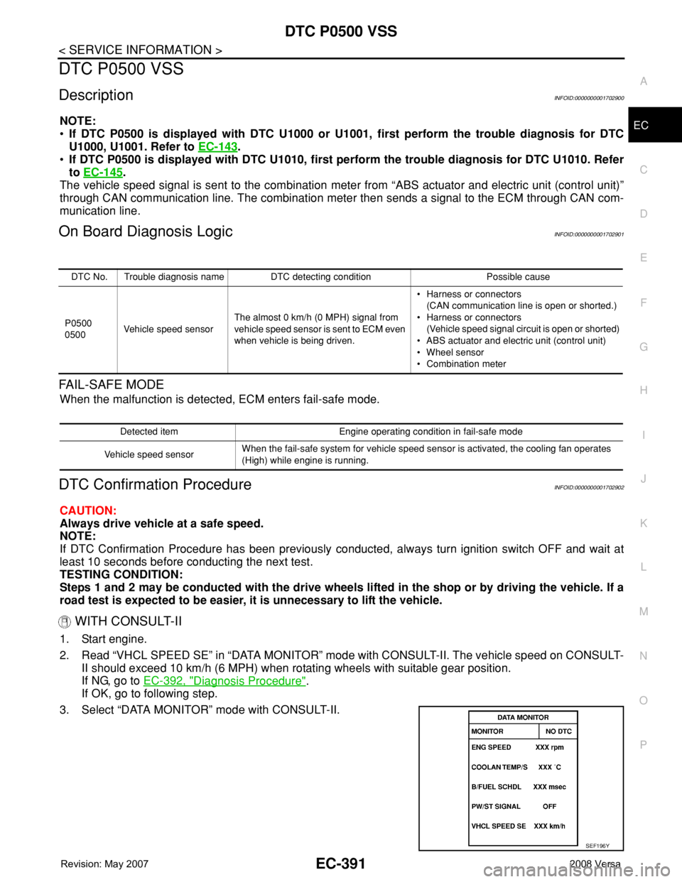
3. Select “DATA MONITOR” mode with CONSULT-II.
DTC No. Trouble diagnosis name DTC detecting condition Possible cause
P0500
0500Vehicle speed sensorThe almost 0 km/h (0 MPH) signal from
vehicle speed sensor is sent to ECM even
when vehicle is being driven.• Harness or connectors
(CAN communication line is open or shorted.)
• Harness or connectors
(Vehicle speed signal circuit is open or shorted)
• ABS actuator and electric unit (control unit)
• Wheel sensor
• Combination meter
Detected item Engine operating condition in fail-safe mode
Vehicle speed sensorWhen the fail-safe system for vehicle speed sensor is activated, the cooling fan operates
(High) while engine is running.
SEF196Y
Page 1466 of 2771

EC-392
< SERVICE INFORMATION >
DTC P0500 VSS
4. Warm engine up to normal operating temperature.
5. Maintain the following conditions for at least 60 consecutive seconds.
6. If 1st trip DTC is detected, go to EC-392, "
Diagnosis Procedure".
Overall Function CheckINFOID:0000000001702903
Use this procedure to check the overall function of the vehicle speed signal circuit. During this check, a 1st trip
DTC might not be confirmed.
WITH GST
1. Lift up drive wheels.
2. Start engine.
3. Read vehicle speed signal in Service $01 with GST.
The vehicle speed signal on GST should be able to exceed 10 km/h (6 MPH) when rotating wheels with
suitable gear position.
4. If NG, go to EC-392, "
Diagnosis Procedure".
Diagnosis ProcedureINFOID:0000000001702904
1.CHECK DTC WITH “ABS ACTUATOR AND ELECTRIC UNIT (CONTROL UNIT)”
Refer to BRC-8
.
OK or NG
OK >> GO TO 2.
NG >> Repair or replace.
2.CHECK COMBINATION METER
Refer to DI-4
.
>>INSPECTION END
ENG SPEED More than 1,600 rpm
COOLAN TEMP/S More than 70°C (158°F)
B/FUEL SCHDL 6.0 - 31.8 msec
Shift lever Suitable position
PW/ST SIGNAL OFF
Page 1513 of 2771
DTC P1572 ASCD BRAKE SWITCH
EC-439
< SERVICE INFORMATION >
C
D
E
F
G
H
I
J
K
L
MA
EC
N
P O
DTC Confirmation ProcedureINFOID:0000000001702961
CAUTION:
Always drive vehicle at a safe speed.
NOTE:
• If DTC Confirmation Procedure has been previously conducted, always turn ignition switch OFF and wait at
least 10 seconds before conducting the next test.
• Procedure for malfunction B is not described here. It takes extremely long time to complete procedure for
malfunction B. By performing procedure for malfunction A, the incident that causes malfunction B can be
detected.
TESTING CONDITION:
Steps 4 and 5 may be conducted with the drive wheels lifted in the shop or by driving the vehicle. If a
road test is expected to be easier, it is unnecessary to lift the vehicle.
WITH CONSULT-II
1. Start engine.
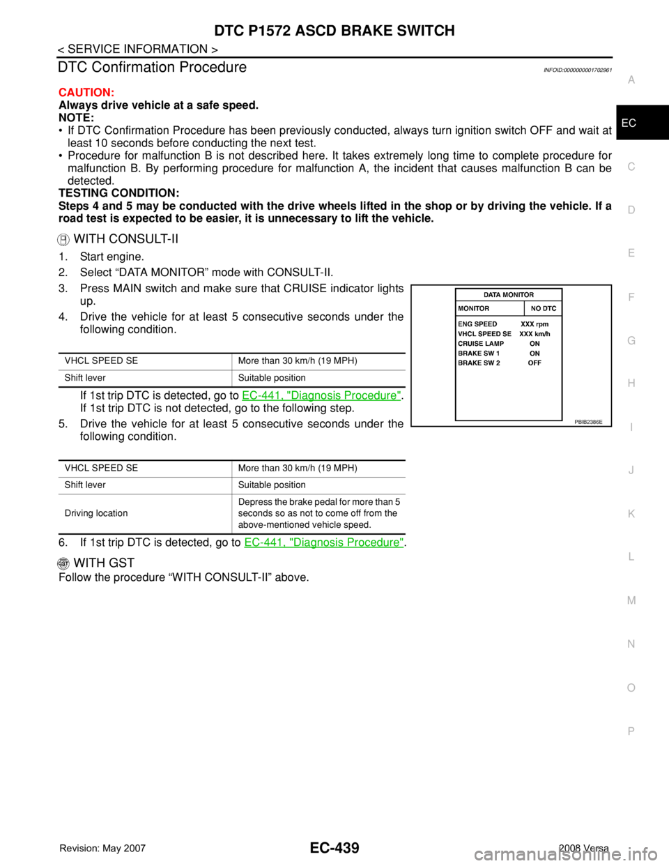
2. Select “DATA MONITOR” mode with CONSULT-II.
3. Press MAIN switch and make sure that CRUISE indicator lights
up.
4. Drive the vehicle for at least 5 consecutive seconds under the
following condition.
If 1st trip DTC is detected, go to EC-441, "
Diagnosis Procedure".
If 1st trip DTC is not detected, go to the following step.
5. Drive the vehicle for at least 5 consecutive seconds under the
following condition.
6. If 1st trip DTC is detected, go to EC-441, "
Diagnosis Procedure".
WITH GST
Follow the procedure “WITH CONSULT-II” above.
VHCL SPEED SE More than 30 km/h (19 MPH)
Shift lever Suitable position
VHCL SPEED SE More than 30 km/h (19 MPH)
Shift lever Suitable position
Driving locationDepress the brake pedal for more than 5
seconds so as not to come off from the
above-mentioned vehicle speed.
PBIB2386E
Page 1521 of 2771
DTC P1574 ASCD VEHICLE SPEED SENSOR
EC-447
< SERVICE INFORMATION >
C
D
E
F
G
H
I
J
K
L
MA
EC
N
P O
DTC P1574 ASCD VEHICLE SPEED SENSOR
Component DescriptionINFOID:0000000001702965
The ECM receives two vehicle speed sensor signals via CAN communication line. One is sent from combina-
tion meter, and the other is from TCM (Transmission control module). The ECM uses these signals for ASCD
control. Refer to EC-28
for ASCD functions.
On Board Diagnosis LogicINFOID:0000000001702966
This self-diagnosis has the one trip detection logic.
The MIL will not light up for this diagnosis.
NOTE:
•If DTC P1574 is displayed with DTC U1000, U1001, first perform the trouble diagnosis for DTC U1000,
U1001. Refer to EC-143
.
•If DTC P1574 is displayed with DTC U1010, first perform the trouble diagnosis for DTC U1010. Refer
to EC-145
.
•If DTC P1574 is displayed with DTC P0500, first perform the trouble diagnosis for DTC P0500. Refer
to EC-391
.
•If DTC P1574 is displayed with DTC P0605, first perform the trouble diagnosis for DTC P0605. Refer
to EC-397
.
DTC Confirmation ProcedureINFOID:0000000001702967
CAUTION:
Always drive vehicle at a safe speed.
NOTE:
If DTC Confirmation Procedure has been previously conducted, always turn ignition switch OFF and wait at
least 10 seconds before conducting the next test.
TESTING CONDITION:
Step 3 may be conducted with the drive wheels lifted in the shop or by driving the vehicle. If a road test
is expected to be easier, it is unnecessary to lift the vehicle.
WITH CONSULT-II
1. Start engine.
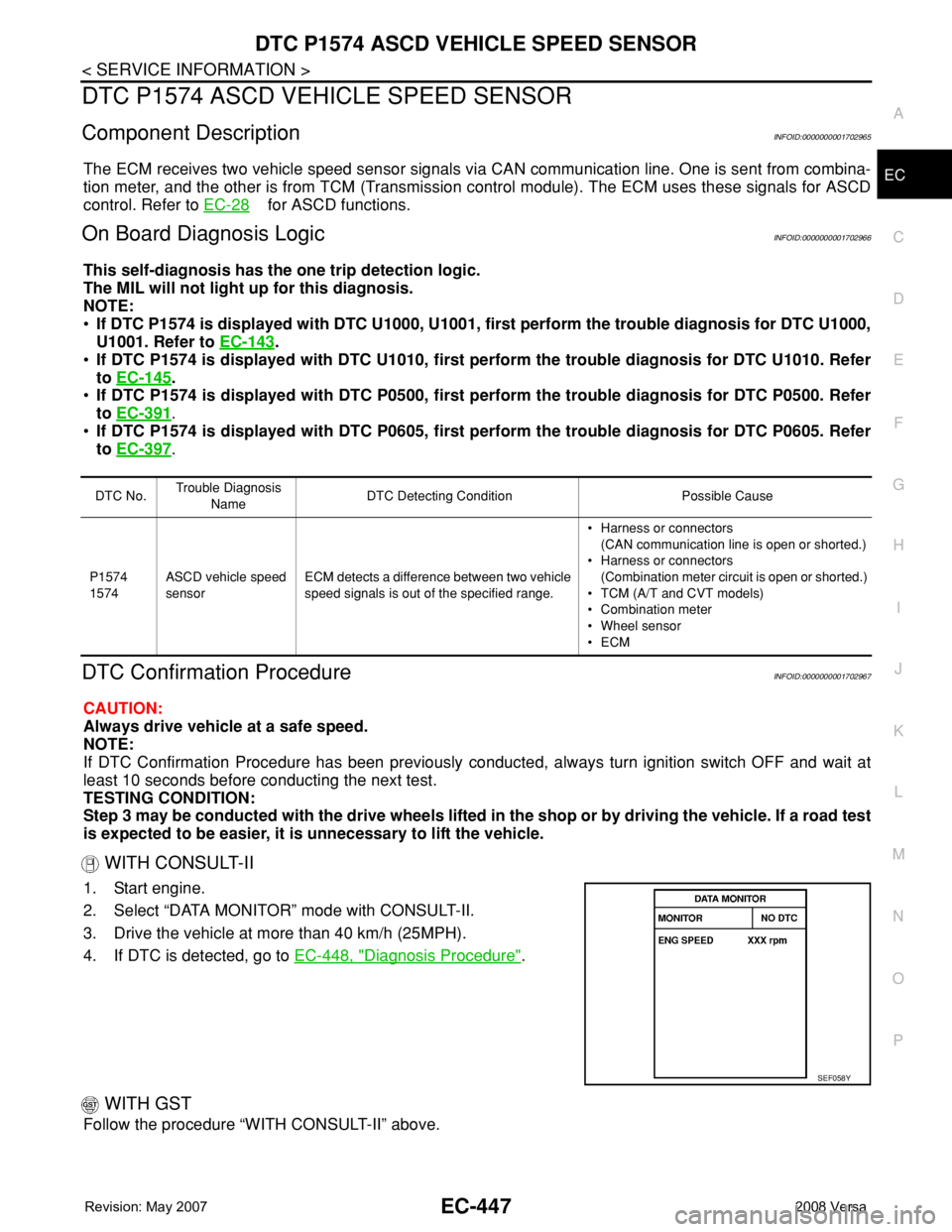
2. Select “DATA MONITOR” mode with CONSULT-II.
3. Drive the vehicle at more than 40 km/h (25MPH).
4. If DTC is detected, go to EC-448, "
Diagnosis Procedure".
WITH GST
Follow the procedure “WITH CONSULT-II” above.
DTC No.Trouble Diagnosis
NameDTC Detecting Condition Possible Cause
P1574
1574ASCD vehicle speed
sensorECM detects a difference between two vehicle
speed signals is out of the specified range.• Harness or connectors
(CAN communication line is open or shorted.)
• Harness or connectors
(Combination meter circuit is open or shorted.)
• TCM (A/T and CVT models)
• Combination meter
• Wheel sensor
•ECM
SEF058Y
Page 1749 of 2771

EM-72
< SERVICE INFORMATION >
ENGINE ASSEMBLY
ENGINE ASSEMBLY
ComponentINFOID:0000000001702507
Removal and InstallationINFOID:0000000001702508
WARNING:
• Situate the vehicle on a flat and solid surface.
• Place chocks at front and back of rear wheels.
• Attach proper slingers and bolts described in PARTS CATALOG if engine slingers are not equipped.
CAUTION:
• Always be careful to work safely, avoid forceful or uninstructed operations.
• Do not start working until exhaust system and coolant are cool enough.
• If items or work required are not covered by the engine section, follow the applicable procedures.
• Always use the support point specified for lifting.
1. Engine mounting Insulator (RH) 2. Engine mounting shim (RH) (if equipped) 3. Engine mounting bracket (RH)
4. Bracket 5. Rear torque rod 6. Engine through bolt
7. Engine mounting bracket (LH) 8. Engine mounting insulator (LH) 9. Torque rod (RH)
A. Front mark B. Silicone lubricant
WBIA0846E
Page 1800 of 2771
FAX-4
< SERVICE INFORMATION >
NOISE, VIBRATION AND HARSHNESS (NVH) TROUBLESHOOTING
NOISE, VIBRATION AND HARSHNESS (NVH) TROUBLESHOOTING
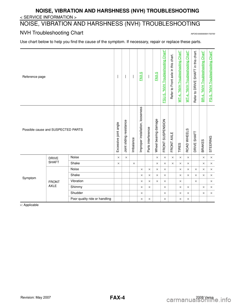
NVH Troubleshooting ChartINFOID:0000000001703700
Use chart below to help you find the cause of the symptom. If necessary, repair or replace these parts.
×: ApplicableReference page
—
—
—
FAX-5—
FAX-5
FSU-5, "
NVH Troubleshooting Chart
"
Refer to Front axle in this chart.
WT-4, "
NVH Troubleshooting Chart
"
WT-4, "
NVH Troubleshooting Chart
"
Refer to DRIVE SHAFT in this chart.
BR-4, "
NVH Troubleshooting Chart
"
PS-5, "
NVH Troubleshooting Chart
"
Possible cause and SUSPECTED PARTS
Excessive joint angle
Joint sliding resistance
Imbalance
Improper installation, looseness
Parts interference
Wheel bearing damage
FRONT SUSPENSION
FRONT AXLE
TIRES
ROAD WHEELS
DRIVE SHAFT
BRAKES
STEERING
SymptomDRIVE
SHAFTNoise×× ××××× ××
Shake× × ××××× ××
FRONT
AXLENoise×××× ×××××
Shake×××× ×××××
Vibration×××××××
Shimmy×××××××
Shudder× × ×× ××
Poor quality ride or handling×××××
Page 1840 of 2771
FSU-6
< SERVICE INFORMATION >
FRONT SUSPENSION ASSEMBLY
FRONT SUSPENSION ASSEMBLY
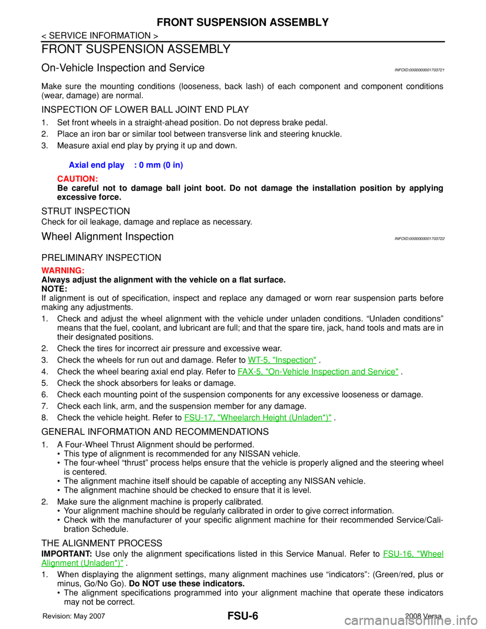
On-Vehicle Inspection and ServiceINFOID:0000000001703721
Make sure the mounting conditions (looseness, back lash) of each component and component conditions
(wear, damage) are normal.
INSPECTION OF LOWER BALL JOINT END PLAY
1. Set front wheels in a straight-ahead position. Do not depress brake pedal.
2. Place an iron bar or similar tool between transverse link and steering knuckle.
3. Measure axial end play by prying it up and down.
CAUTION:
Be careful not to damage ball joint boot. Do not damage the installation position by applying
excessive force.
STRUT INSPECTION
Check for oil leakage, damage and replace as necessary.
Wheel Alignment InspectionINFOID:0000000001703722
PRELIMINARY INSPECTION
WARNING:
Always adjust the alignment with the vehicle on a flat surface.
NOTE:
If alignment is out of specification, inspect and replace any damaged or worn rear suspension parts before
making any adjustments.
1. Check and adjust the wheel alignment with the vehicle under unladen conditions. “Unladen conditions”
means that the fuel, coolant, and lubricant are full; and that the spare tire, jack, hand tools and mats are in
their designated positions.
2. Check the tires for incorrect air pressure and excessive wear.
3. Check the wheels for run out and damage. Refer to WT-5, "
Inspection" .
4. Check the wheel bearing axial end play. Refer to FA X - 5 , "
On-Vehicle Inspection and Service" .
5. Check the shock absorbers for leaks or damage.
6. Check each mounting point of the suspension components for any excessive looseness or damage.
7. Check each link, arm, and the suspension member for any damage.
8. Check the vehicle height. Refer to FSU-17, "
Wheelarch Height (Unladen*)" .
GENERAL INFORMATION AND RECOMMENDATIONS
1. A Four-Wheel Thrust Alignment should be performed.
• This type of alignment is recommended for any NISSAN vehicle.
• The four-wheel “thrust” process helps ensure that the vehicle is properly aligned and the steering wheel
is centered.
• The alignment machine itself should be capable of accepting any NISSAN vehicle.
• The alignment machine should be checked to ensure that it is level.
2. Make sure the alignment machine is properly calibrated.
• Your alignment machine should be regularly calibrated in order to give correct information.
• Check with the manufacturer of your specific alignment machine for their recommended Service/Cali-
bration Schedule.
THE ALIGNMENT PROCESS
IMPORTANT: Use only the alignment specifications listed in this Service Manual. Refer to FSU-16, "Wheel
Alignment (Unladen*)" .
1. When displaying the alignment settings, many alignment machines use “indicators”: (Green/red, plus or
minus, Go/No Go). Do NOT use these indicators.
• The alignment specifications programmed into your alignment machine that operate these indicators
may not be correct.Axial end play : 0 mm (0 in)
Page 1841 of 2771
FRONT SUSPENSION ASSEMBLY
FSU-7
< SERVICE INFORMATION >
C
D
F
G
H
I
J
K
L
MA
B
FSU
N
O
P
• This may result in an ERROR.
2. Some newer alignment machines are equipped with an optional “Rolling Compensation” method to “com-
pensate” the sensors (alignment targets or head units). Do NOT use this “Rolling Compensation”
method.
• Use the “Jacking Compensation” method. After installing the alignment targets or head units, raise the
vehicle and rotate the wheels 1/2 turn both ways.
• See Instructions in the alignment machine you are using for more information.
CAMBER, CASTER AND KINGPIN INCLINATION ANGLES INSPECTION
• Camber, caster, kingpin inclination angles cannot be adjusted.
• Before inspection, mount front wheels onto turning radius gauge. Mount rear wheels onto a stand that has
same height so vehicle will remain horizontal.
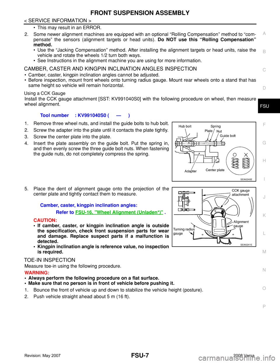
Using a CCK Gauge
Install the CCK gauge attachment [SST: KV991040S0] with the following procedure on wheel, then measure
wheel alignment.
1. Remove three wheel nuts, and install the guide bolts to hub bolt.
2. Screw the adapter into the plate until it contacts the plate tightly.
3. Screw the center plate into the plate.
4. Insert the plate assembly on the guide bolt. Put the spring in,
and then evenly screw the three guide bolt nuts. When fastening
the guide nuts, do not completely compress the spring.
5. Place the dent of alignment gauge onto the projection of the
center plate and tightly contact them to measure.
CAUTION:
• If camber, caster, or kingpin inclination angle is outside
the specification, check front suspension parts for wear
and damage. Replace suspect parts if a malfunction is
detected.
• Kingpin inclination angle is reference value, no inspection
is required.
TOE-IN INSPECTION
Measure toe-in using the following procedure.
WARNING:
• Always perform the following procedure on a flat surface.
• Make sure that no person is in front of vehicle before pushing it.
1. Bounce the front of vehicle up and down to stabilize the vehicle height (posture).
2. Push vehicle straight ahead about 5 m (16 ft).Tool number : KV991040S0 ( — )
SEIA0240E
Camber, caster, kingpin inclination angles:
Refer to FSU-16, "
Wheel Alignment (Unladen*)" .
SEIA0241E
Page 1842 of 2771
FSU-8
< SERVICE INFORMATION >
FRONT SUSPENSION ASSEMBLY
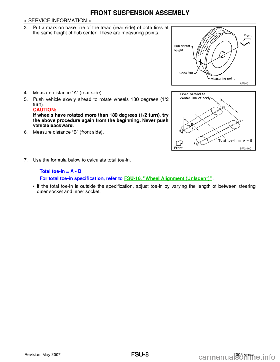
3. Put a mark on base line of the tread (rear side) of both tires at
the same height of hub center. These are measuring points.
4. Measure distance “A” (rear side).
5. Push vehicle slowly ahead to rotate wheels 180 degrees (1/2
turn).
CAUTION:
If wheels have rotated more than 180 degrees (1/2 turn), try
the above procedure again from the beginning. Never push
vehicle backward.
6. Measure distance “B” (front side).
7. Use the formula below to calculate total toe-in.
• If the total toe-in is outside the specification, adjust toe-in by varying the length of between steering
outer socket and inner socket.
AFA050
SFA234AC
Total toe-in = A - B
For total toe-in specification, refer to FSU-16, "
Wheel Alignment (Unladen*)" .