NISSAN TIIDA 2008 Service Repair Manual
Manufacturer: NISSAN, Model Year: 2008, Model line: TIIDA, Model: NISSAN TIIDA 2008Pages: 2771, PDF Size: 60.61 MB
Page 2671 of 2771
SPIRAL CABLE
SRS-37
< ON-VEHICLE REPAIR >
C
D
E
F
G
I
J
K
L
MA
B
SRS
N
O
P
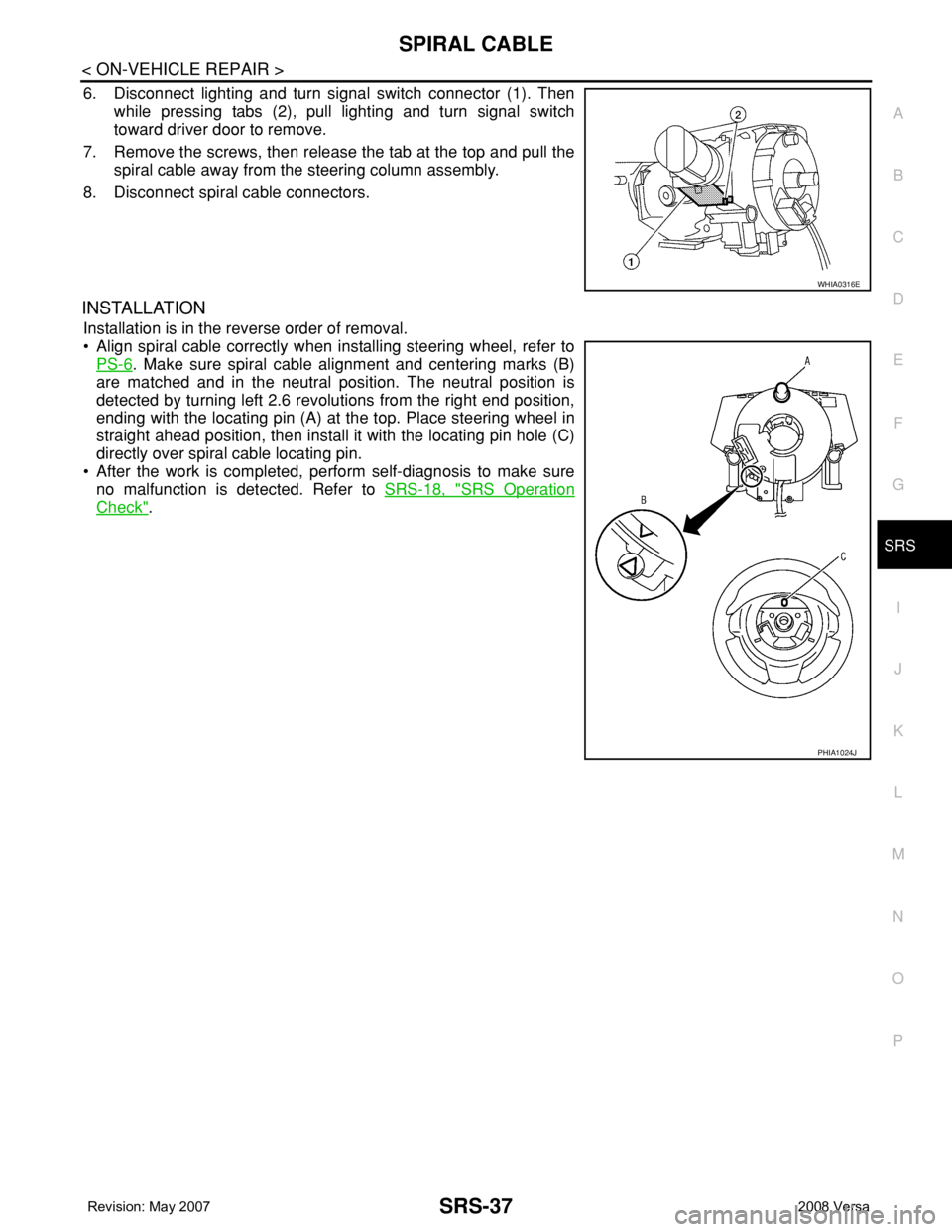
6. Disconnect lighting and turn signal switch connector (1). Then
while pressing tabs (2), pull lighting and turn signal switch
toward driver door to remove.
7. Remove the screws, then release the tab at the top and pull the
spiral cable away from the steering column assembly.
8. Disconnect spiral cable connectors.
INSTALLATION
Installation is in the reverse order of removal.
• Align spiral cable correctly when installing steering wheel, refer to
PS-6
. Make sure spiral cable alignment and centering marks (B)
are matched and in the neutral position. The neutral position is
detected by turning left 2.6 revolutions from the right end position,
ending with the locating pin (A) at the top. Place steering wheel in
straight ahead position, then install it with the locating pin hole (C)
directly over spiral cable locating pin.
• After the work is completed, perform self-diagnosis to make sure
no malfunction is detected. Refer to SRS-18, "
SRS Operation
Check".
WHIA0316E
PHIA1024J
Page 2672 of 2771
SRS-38
< ON-VEHICLE REPAIR >
FRONT PASSENGER AIR BAG MODULE
FRONT PASSENGER AIR BAG MODULE
Removal and InstallationINFOID:0000000001703928
REMOVAL
WARNING:
• When servicing the SRS, do not work from directly in front of air bag module.
• Always place front passenger air bag module with pad side facing upward.
CAUTION:
• Before servicing SRS, turn the ignition switch OFF, disconnect both battery cables and wait at least
3 minutes.
• Do not use old bolts after removal; replace with new bolts.
• Do not insert any foreign objects (screwdriver, etc.) into air bag module or harness connectors.
• Do not disassemble air bag module.
• Do not expose the front passenger air bag module to temperatures exceeding 90°C (194°F).
• Replace the front passenger air bag module if it has been
dropped or sustained an impact.
• Do not allow oil, grease or water to come in contact with the
front passenger air bag module.
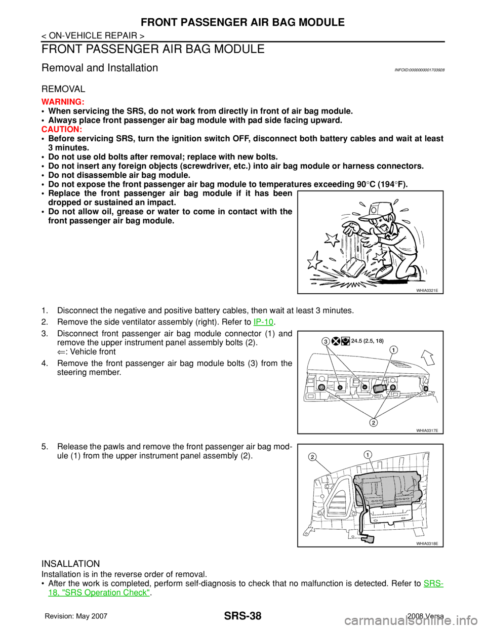
1. Disconnect the negative and positive battery cables, then wait at least 3 minutes.
2. Remove the side ventilator assembly (right). Refer to IP-10
.
3. Disconnect front passenger air bag module connector (1) and
remove the upper instrument panel assembly bolts (2).
⇐: Vehicle front
4. Remove the front passenger air bag module bolts (3) from the
steering member.
5. Release the pawls and remove the front passenger air bag mod-
ule (1) from the upper instrument panel assembly (2).
INSALLATION
Installation is in the reverse order of removal.
• After the work is completed, perform self-diagnosis to check that no malfunction is detected. Refer to SRS-
18, "SRS Operation Check".
WHIA0321E
WHIA0317E
WHIA0318E
Page 2673 of 2771
SIDE CURTAIN AIR BAG MODULE
SRS-39
< ON-VEHICLE REPAIR >
C
D
E
F
G
I
J
K
L
MA
B
SRS
N
O
P
SIDE CURTAIN AIR BAG MODULE
ComponentINFOID:0000000001703929
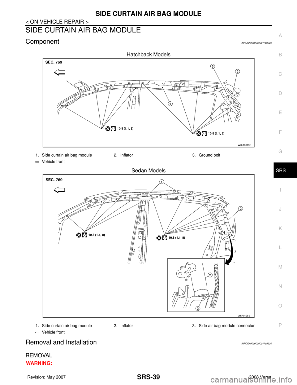
Hatchback Models
Sedan Models
Removal and InstallationINFOID:0000000001703930
REMOVAL
WARNING:
WHIA0319E
1. Side curtain air bag module 2. Inflator 3. Ground bolt
⇐Vehicle front
LHIA0135E
1. Side curtain air bag module 2. Inflator 3. Side air bag module connector
⇐Vehicle front
Page 2674 of 2771
SRS-40
< ON-VEHICLE REPAIR >
SIDE CURTAIN AIR BAG MODULE
• When servicing the SRS, do not work from directly in front of air bag module.
• Always place the curtain air bag module with deployment side facing upward.
• Do not reuse center pillar upper garnish if removed.
CAUTION:
• Before servicing SRS, turn the ignition switch OFF, disconnect both battery cables and wait at least
3 minutes.
• Do not use old bolts after removal; replace with new bolts.
• Do not insert any foreign objects (screwdriver, etc.) into air bag module or harness connectors.
• Do not disassemble air bag module.
• Do not expose the side curtain air bag module to temperatures exceeding 90°C (194°F).
• Replace the side curtain air bag module if it has been dropped
or sustained an impact.
• Do not allow oil, grease or water to come in contact with the
side curtain air bag module.
• Do not attempt to repair or replace damaged direct-connect
SRS component connectors. If a direct-connect harness con-
nector is damaged, the harness must be replaced.
1. Disconnect both the negative and positive battery cables, then wait at least 3 minutes.
2. Remove the headlining. Refer to EI-45
.
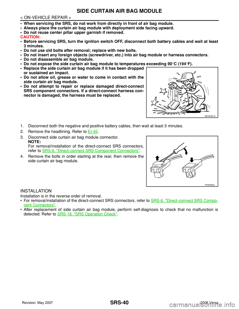
3. Disconnect side curtain air bag module connector.
NOTE:
For removal/installation of the direct-connect SRS connectors,
refer to SRS-6, "
Direct-connect SRS Component Connectors".
4. Remove the bolts in order starting at the rear, then remove the
side curtain air bag module.
INSTALLATION
Installation is in the reverse order of removal.
• For removal/installation of the direct-connect SRS connectors, refer to SRS-6, "
Direct-connect SRS Compo-
nent Connectors".
• After replacement of side curtain air bag module, perform self-diagnosis to check that no malfunction is
detected. Refer to SRS-18, "
SRS Operation Check".
WHIA0321E
PHIA0953J
Page 2675 of 2771
CRASH ZONE SENSOR
SRS-41
< ON-VEHICLE REPAIR >
C
D
E
F
G
I
J
K
L
MA
B
SRS
N
O
P
CRASH ZONE SENSOR
Removal and InstallationINFOID:0000000001703931
REMOVAL
CAUTION:
• Before servicing the SRS, turn ignition switch OFF, disconnect both battery cables and wait at least
3 minutes.
• Do not disassemble the crash zone sensor.
• Do not use old nuts after removal; replace with new nuts.
• Replace the crash zone sensor if it has been dropped or sus-
tained an impact.
• Check crash zone sensor to make sure it is free of deformi-
ties, dents, cracks or rust. If it shows any visible signs of dam-
age, replace it with a new one.
1. Disconnect both the negative and positive battery cables, then wait at least 3 minutes.
2. Remove upper radiator cover and front grille, refer to EI-20
.
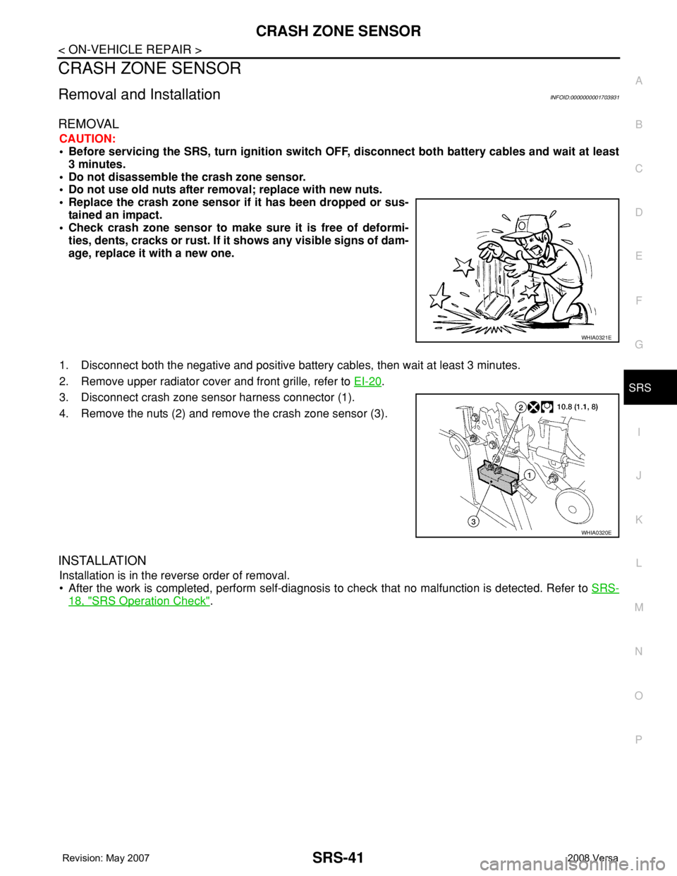
3. Disconnect crash zone sensor harness connector (1).
4. Remove the nuts (2) and remove the crash zone sensor (3).
INSTALLATION
Installation is in the reverse order of removal.
• After the work is completed, perform self-diagnosis to check that no malfunction is detected. Refer to SRS-
18, "SRS Operation Check".
WHIA0321E
WHIA0320E
Page 2676 of 2771
SRS-42
< ON-VEHICLE REPAIR >
SIDE AIR BAG (SATELLITE) SENSOR
SIDE AIR BAG (SATELLITE) SENSOR
Removal and InstallationINFOID:0000000001703932
REMOVAL
WARNING:
Do not reuse center pillar upper garnish if removed.
CAUTION:
• Before servicing the SRS, turn ignition switch OFF, disconnect both battery cables and wait at least
3 minutes.
• Do not disassemble the side air bag (satellite) sensor.
• Do not use old nuts after removal; replace with new nuts.
• Replace the side air bag (satellite) sensor if it has been
dropped or sustained an impact.
• Check side air bag (satellite) sensor to make sure it is free of
deformities, dents, cracks or rust. If it shows any visible signs
of damage, replace it with a new one.
1. Disconnect both the negative and positive battery cables, then wait at least 3 minutes.
2. Remove the front seat belt retractor. Refer to SB-3, "
Removal and Installation of Front Seat Belt".
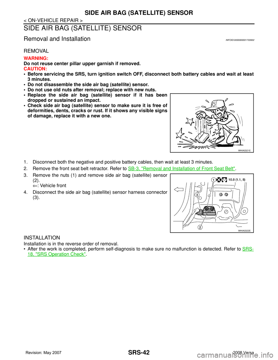
3. Remove the nuts (1) and remove side air bag (satellite) sensor
(2).
⇐: Vehicle front
4. Disconnect the side air bag (satellite) sensor harness connector
(3).
INSTALLATION
Installation is in the reverse order of removal.
• After the work is completed, perform self-diagnosis to make sure no malfunction is detected. Refer to SRS-
18, "SRS Operation Check".
WHIA0321E
WHIA0322E
Page 2677 of 2771

FRONT SEAT BELT PRE-TENSIONER
SRS-43
< ON-VEHICLE REPAIR >
C
D
E
F
G
I
J
K
L
MA
B
SRS
N
O
P
FRONT SEAT BELT PRE-TENSIONER
Removal and InstallationINFOID:0000000001703933
For removal and installation procedures, refer to SB-3, "Removal and Installation of Front Seat Belt".
Page 2678 of 2771
SRS-44
< ON-VEHICLE REPAIR >
DIAGNOSIS SENSOR UNIT
DIAGNOSIS SENSOR UNIT
Removal and InstallationINFOID:0000000001703934
REMOVAL
WARNING:
Before disconnecting diagnosis sensor unit harness connector(s), be sure to disconnect harness con-
nectors from air bag modules and front seat belt pre-tensioner to prevent deployment by static elec-
tricity.
CAUTION:
• Before servicing the SRS, turn the ignition switch OFF, disconnect both battery cables and wait at
least 3 minutes.
• Do not disassemble diagnosis sensor unit.
• Do not use old bolts; replace with new bolts.
• Replace the diagnosis sensor unit if it has been dropped or sustained an impact.
• Check diagnosis sensor unit bracket to make sure it is free of deformities, dents, cracks or rust. If it
shows any visible signs of damage, replace with new one.
• The diagnosis sensor unit must always be installed with the arrow mark "⇐" pointing toward the
front of the vehicle for proper operation.
1. Disconnect the negative and positive battery cables, then wait at least 3 minutes.
2. Disconnect the harness connectors for each air bag module and seat belt pre-tensioner. Refer to SRS-33
,
SRS-38
, SRS-39, SRS-43.
3. Remove center console assembly. Refer to IP-10
.
4. Disconnect diagnosis sensor unit connectors.
5. Remove the bolts and the ground bolt, then remove the diagnosis sensor unit.
INSTALLATION
Installation is in the reverse order of removal.
• The diagnosis sensor unit must always be installed with the arrow mark "⇐" pointing toward the front of the
vehicle.
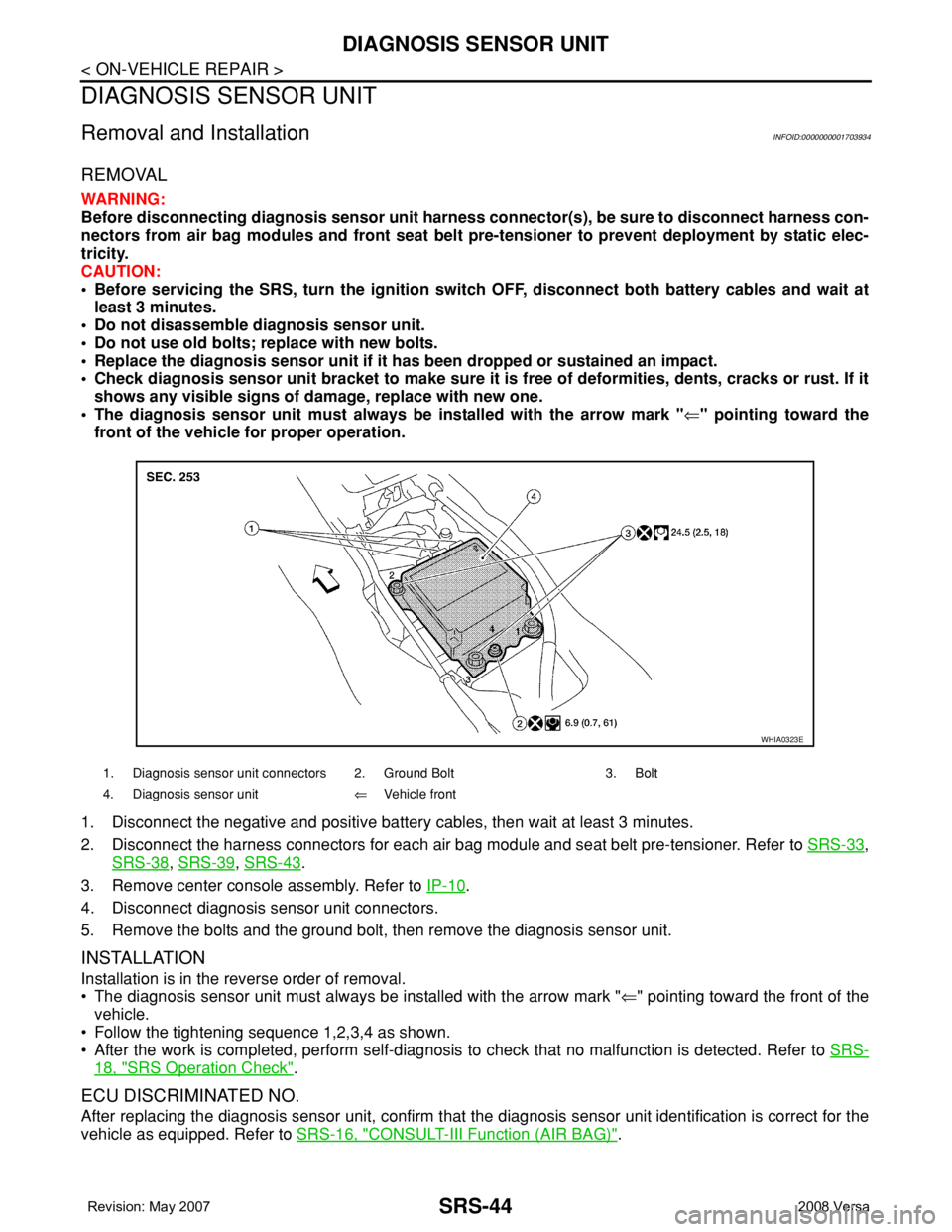
• Follow the tightening sequence 1,2,3,4 as shown.
• After the work is completed, perform self-diagnosis to check that no malfunction is detected. Refer to SRS-
18, "SRS Operation Check".
ECU DISCRIMINATED NO.
After replacing the diagnosis sensor unit, confirm that the diagnosis sensor unit identification is correct for the
vehicle as equipped. Refer to SRS-16, "
CONSULT-III Function (AIR BAG)".
1. Diagnosis sensor unit connectors 2. Ground Bolt 3. Bolt
4. Diagnosis sensor unit⇐Vehicle front
WHIA0323E
Page 2679 of 2771

OCCUPANT CLASSIFICATION SYSTEM CONTROL UNIT
SRS-45
< ON-VEHICLE REPAIR >
C
D
E
F
G
I
J
K
L
MA
B
SRS
N
O
P
OCCUPANT CLASSIFICATION SYSTEM CONTROL UNIT
Removal and InstallationINFOID:0000000001703935
The occupant classification system control unit, occupant classification system sensor, and bladder are an
integral part of the front passenger seat cushion and are replaced as an assembly. Refer to SE-10
to remove
the seat, and SE-12, "
Disassembly and Assembly" to replace the seat cushion.
Page 2680 of 2771

SRS-46
< ON-VEHICLE REPAIR >
COLLISION DIAGNOSIS
COLLISION DIAGNOSIS
For Frontal CollisionINFOID:0000000001703936
Check the SRS components using the following table.
• After the work is completed, perform self-diagnosis to check that no malfunction is detected. Refer to SRS-
18, "SRS Operation Check".
SRS INSPECTION (FOR FRONTAL COLLISION)
Part SRS is activated SRS is NOT activated
Driver air bag module If the driver air bag
has deployed:
REPLACE
Install with new fas-
teners.If the driver air bag has NOT been activated:
1. Remove driver air bag module. Check harness cover and connectors for dam-
age, terminals for deformities, and harness for binding.
2. Install driver air bag module into the steering wheel to check fit and alignment
with the wheel.
3. If no damage is found, reinstall with new fasteners.
4. If damaged—REPLACE. Install driver air bag modules with new fasteners.
Front passenger air
bag moduleIf the front passenger
air bag has deployed:
REPLACE
Install with new fas-
teners.If the front passenger air bag has NOT been activated:
1. Remove front passenger air bag module. Check harness cover and connectors
for damage, terminals for deformities, and harness for binding.
2. Install front passenger air bag module into the instrument panel to check fit with
the instrument panel.
3. If no damage is found, reinstall with new fasteners.
4. If damaged—REPLACE. Install front passenger air bag modules with new fas-
teners.
Crash zone sensor If any of the front air
bags or seat belt pre-
tensioners* have
been activated:
REPLACE the crash
zone sensor and
bracket with new fas-
teners.
*: Confirm seat belt
pre-tensioner activa-
tion using CONSULT-
III only.If the front air bags or seat belt pre-tensioners have NOT been activated:
1. Remove the crash zone sensor. Check harness connectors for damage, termi-
nals for deformities, and harness for binding.
2. Check for visible signs of damage (dents, cracks, deformation) of the crash zone
sensor and bracket.
3. Install the crash zone sensor to check fit.
4. If no damage is found, reinstall with new fasteners.
5. If damaged—REPLACE the crash zone sensor and bracket with new fasteners.
Seat belt pre-tension-
er assemblies
(All applicable loca-
tions: buckle, reel, lap
outer)If either the driver or
passenger seat belt
pre-tensioner* has
been activated:
REPLACE all seat
belt pre-tensioner as-
semblies with new
fasteners.
*: Confirm seat belt
pre-tensioner activa-
tion using CONSULT-
III only.If the pre-tensioners have NOT been activated:
1. Remove seat belt pre-tensioners.
Check harness cover and connectors for damage, terminals for deformities, and
harness for binding.
2. Check belts for damage and anchors for loose mounting.
3. Check retractor for smooth operation.
4. Check seat belt adjuster for damage.
5. Check for deformities of the center pillar inner.
6. If the center pillar inner has no damage, REPLACE the seat belt pre-tensioner
assembly.
7. If no damage is found, reinstall seat belt pre-tensioner assembly.
8. If damaged—REPLACE. Install the seat belt pre-tensioners with new fasteners.
Diagnosis sensor unit If any of the SRS com-
ponents have been
activated:
REPLACE the diag-
nosis sensor unit.
Install with new fas-
teners.If none of the SRS components have been activated:
1. Check case for dents, cracks or deformities.
2. Check connectors for damage, and terminals for deformities.
3. If no damage is found, reinstall with new fasteners.
4. If damaged—REPLACE. Install diagnosis sensor unit with new fasteners.