Engine Control System NISSAN TIIDA 2008 Service Owner's Manual
[x] Cancel search | Manufacturer: NISSAN, Model Year: 2008, Model line: TIIDA, Model: NISSAN TIIDA 2008Pages: 2771, PDF Size: 60.61 MB
Page 220 of 2771

AT-208
< SERVICE INFORMATION >
SHIFT CONTROL SYSTEM
5. The method of operating selector lever to individual positions
correctly should be as shown.
• (A): Press selector button to operate selector lever, while
depressing the brake pedal.
• (B): Press selector button to operate selector lever.
• (C): Selector lever can be operated without pressing selector
button.
6. Confirm back-up lamps illuminate only when selector lever is
placed in “R” position. Confirm back-up lamps do not illuminate
when selector lever is in “P” or “N” position even if it is pushed
toward “R” position without pressing selector button.
7. Confirm engine can only be started with selector lever in “P” and
“N” positions.
8. Make sure A/T is locked completely in “P” position.
WCIA0636E
Page 223 of 2771
A/T SHIFT LOCK SYSTEM
AT-211
< SERVICE INFORMATION >
D
E
F
G
H
I
J
K
L
MA
B
AT
N
O
P
•Selector lever can be moved from “P” position with ignition key in ON position and brake pedal
released.
•Selector lever can be moved from “P” position when ignition switch is removed from key cylinder.
SYMPTOM 2:
•Ignition key cannot be removed when selector lever is set to “P” position.
•Ignition key can be removed when selector lever is set to any position except “P” position.
1.CHECK KEY INTERLOCK CABLE
Check key interlock cable for damage.
OK or NG
OK >> GO TO 2.
NG >> Repair key interlock cable. Refer to AT-213, "
Removal and Installation" .
2.CHECK A/T POSITION
Check A/T position. Refer to AT-207, "
Checking of A/T Position" .
OK or NG
OK >> GO TO 3.
NG >> Adjust control cable. Refer to AT-207, "
Adjustment of A/T Position" .
3.CHECK SHIFT LOCK SOLENOID AND PARK POSITION SWITCH
1. Turn ignition switch ON. (Do not start engine.)
2. Selector lever is set in “P” position.
3. Check operation sound.
OK or NG
OK >>INSPECTION END
NG >> GO TO 4.
4.CHECK POWER SOURCE
1. Turn ignition switch ON. (Do not start engine.)
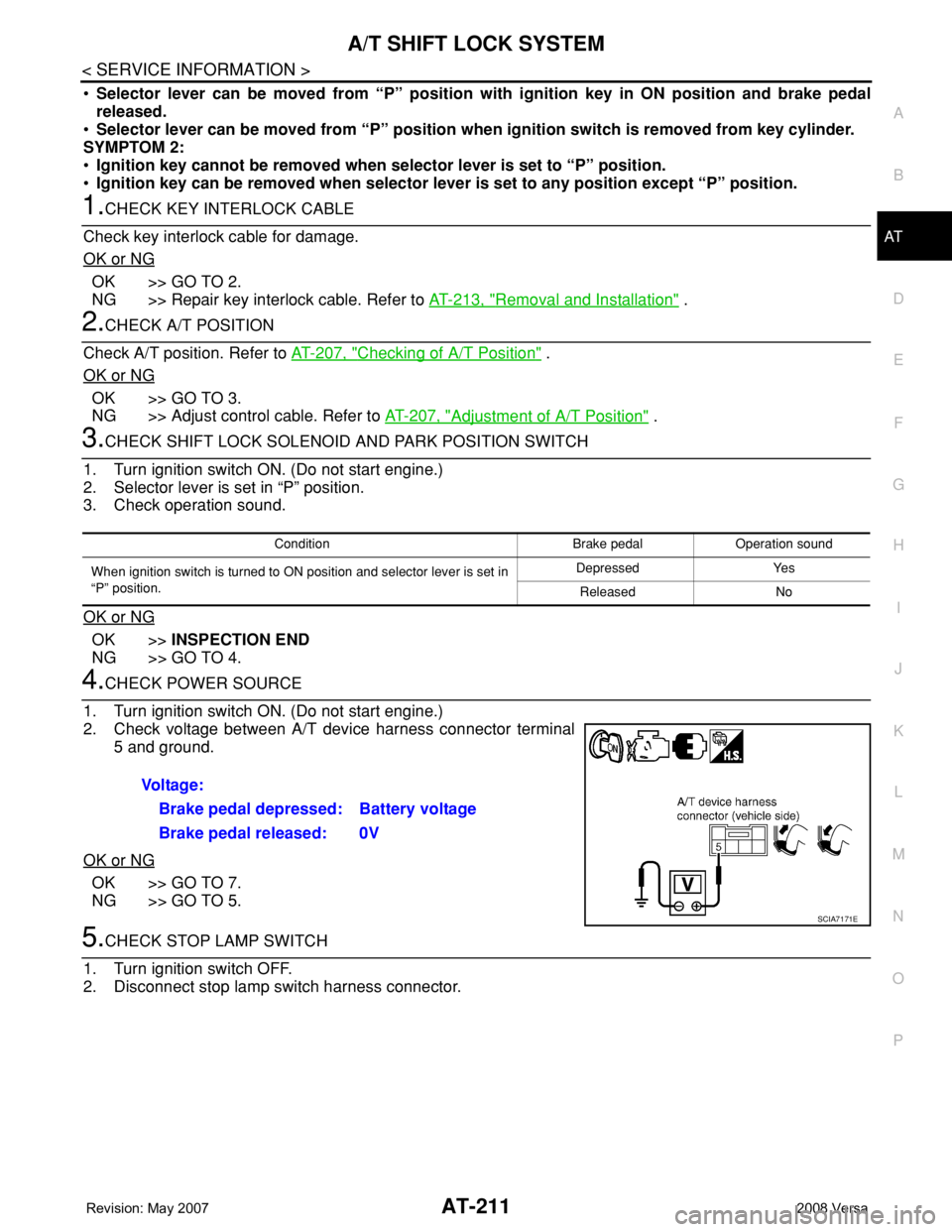
2. Check voltage between A/T device harness connector terminal
5 and ground.
OK or NG
OK >> GO TO 7.
NG >> GO TO 5.
5.CHECK STOP LAMP SWITCH
1. Turn ignition switch OFF.
2. Disconnect stop lamp switch harness connector.
Condition Brake pedal Operation sound
When ignition switch is turned to ON position and selector lever is set in
“P” position.Depressed Yes
Released No
Voltage:
Brake pedal depressed: Battery voltage
Brake pedal released: 0V
SCIA7171E
Page 510 of 2771
BL-76
< SERVICE INFORMATION >
INTELLIGENT KEY SYSTEM
System Description
INFOID:0000000001703999
• The Intelligent Key system is a system that makes it possible to lock and unlock the door locks (door lock/
unlock function), and start the engine (engine start function) by carrying around the Intelligent Key (without
some key operation), which operates based on the results of electronic ID verification using two-way com-
munications between the Intelligent Key and the vehicle (Intelligent Key unit).
• Vehicles equipped with a manual transmission include a key interlock solenoid located in the steering col-
umn to prevent accidental shut-off of the ignition switch and locking of the steering wheel during driving con-
dition when the vehicle is moving.
CAUTION:
The driver should always carry the Intelligent Key
• Operation of the remote controller buttons on the Intelligent Key also provides the same functions as the
remote control entry system. (Remote keyless entry functions)
• If an action that does not meet the operating conditions of the Intelligent Key system is taken, the buzzer
goes off to inform the driver. (Warning chime functions)
• When a door lock is locked or unlocked with request switch or remote controller button operation, the hazard
lamps flash and the buzzer (outside vehicle) sounds (Hazard and buzzer reminder function).
• Even if the Intelligent Key battery is completely discharged, the door locks can be locked and unlocked and
the engine started with the mechanical key built into the Intelligent Key.
• The settings for each function can be changed with the CONSULT-III.
• If an Intelligent Key is lost, a new Intelligent Key can be registered. A maximum of 4 Intelligent Keys can be
registered.
• It has been made possible to diagnose the system and register an Intelligent Key with the CONSULT-III.
DOOR LOCK/UNLOCK FUNCTION
Only when pressing the request switch, it is possible to lock and unlock the door by carrying around the Intelli-
gent Key (without some key operation).
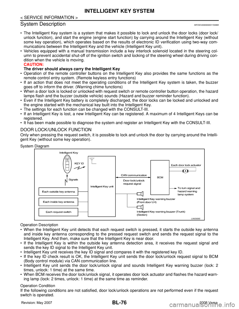
System Diagram
Operation Description
• When the Intelligent Key unit detects that each request switch is pressed, it starts the outside key antenna
and inside key antenna corresponding to the pressed request switch and sends the request signal to the
Intelligent Key. And then, make sure that the Intelligent Key is near door.
• If the Intelligent Key is within the outside key antenna detection area, it receives the request signal and
sends the key ID signal to the Intelligent Key unit.
• Intelligent Key unit receives the key ID signal and compares it with the registered key ID.
• If the key ID check result is OK, the Intelligent Key unit sends the door lock/unlock request signal to BCM
(Body control module) via CAN communication line.
• Intelligent Key unit sends the door lock/unlock signal and sounds Intelligent Key warning buzzer (lock: 2
times, unlock: 1 time) at the same time.
• When BCM receives the door lock/unlock signal, it operates door lock actuator and flashes the hazard warn-
ing lamp (lock: 2 times, unlock: 1 time) at the same time as reminder.
Operation Condition
If the following conditions are not satisfied, door lock/unlock operations are not performed even if the request
switch is operated.
LIIA2926E
Page 514 of 2771
BL-80
< SERVICE INFORMATION >
INTELLIGENT KEY SYSTEM
BCM sends headlamp request signal and horn signal to IPDM E/R. Then, IPDM E/R turns on and off head-
lamp and horn intermittently.
The headlamp flashes and the horn sounds intermittently.
The alarm automatically turns off:
• After 25 seconds
• When Intelligent Key unit receives any signal from remote controller of Intelligent Key
• When door request switch is pressed (Intelligent Key is outside vehicle)
Panic alarm function's press and holding time value can be changed in “PANIC ALARM DELAY” mode in
“WORK SUPPORT”. Refer to BL-101, "
CONSULT-III Application Item".
List of Operation Related Parts
Parts marked with × are the parts related to operation.
ENGINE START FUNCTION
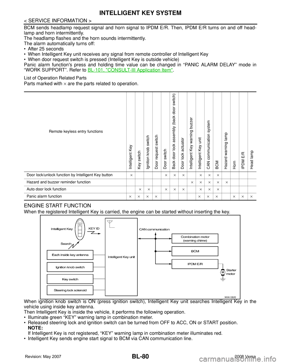
When the registered Intelligent Key is carried, the engine can be started without inserting the key.
When ignition knob switch is ON (press ignition switch), Intelligent Key unit searches Intelligent Key in the
vehicle using inside key antenna.
Then Intelligent Key is inside the vehicle, it performs the following operation.
• Illuminate green “KEY” warning lamp in combination meter.
• Released steering lock and ignition switch can be turned from OFF to ACC, ON or START position.
NOTE:
If Intelligent Key is not registered, “KEY” warning lamp in combination meter illuminates red.
• Intelligent Key sends engine start signal to BCM via CAN communication line.
Remote keyless entry functions
Intelligent Key
Key switch
Ignition knob switch
Door request switch
Door switch
Back door lock assembly (back door switch)
Door lock actuator
Intelligent Key warning buzzer
Intelligent Key unit
CAN communication system
BCM
Hazard warning lamp
Horn
IPDM E/R
Head lamp
Door lock/unlock function by Intelligent Key button×××××××
Hazard and buzzer reminder function×××××
Auto door lock function×× ××× ×××
Panic alarm function×××× ××× ×××
WIIA1282E
Page 537 of 2771

INTELLIGENT KEY SYSTEM
BL-103
< SERVICE INFORMATION >
C
D
E
F
G
H
J
K
L
MA
B
BL
N
O
P
Trouble Diagnosis Symptom ChartINFOID:0000000001704012
KEY WARNING LAMP (GREEN) ILLUMINATES
NOTE:
• Before performing the diagnosis in the following table, check “Trouble Diagnosis Procedure”. Refer to BL-99,
"Trouble Diagnosis Procedure".
• Make sure that vehicle is under the condition shown in “Conditions of vehicle” before starting diagnosis, and
check each symptom.
• If the following “symptoms” are detected, check systems shown in the “Diagnoses/service procedure” col-
umn in this order.
Conditions of Vehicle (Operating Conditions)
• Intelligent Key is registered.
• Key is not inserted in ignition switch.
• One or more registered Intelligent Keys are in the vehicle.
KEY WARNING LAMP (RED) ILLUMINATES
NOTE:
• Before performing the diagnosis in the following table, check “Trouble Diagnosis Procedure”. Refer to BL-99,
"Trouble Diagnosis Procedure".
• Make sure that vehicle is under the condition shown in “Conditions of vehicle” before starting diagnosis, and
check each symptom.
• If the following “symptoms” are detected, check systems shown in the “Diagnoses/service procedure” col-
umn in this order.
Conditions of Vehicle (Operating Conditions)
• Intelligent Key is registered.
ANSWER BACK WITH I-KEY
LOCKBuzzer reminder function (lock operation) mode by door request switch (driver side, passenger
side and back door side) can be selected from the following with this mode. The operation mode
will be changed when “CHANGE SETT” on CONSULT-III screen is touched.
• BUZZER: Sound buzzer
• OFF: Non-operation
ANSWER BACK WITH I-KEY UN-
LOCKBuzzer reminder function (unlock operation) mode by door request switch can be changed to op-
erate (ON) or not operate (OFF) with this mode.
AUTO RELOCK TIMERAuto door lock timer mode can select the following with this mode.
• 1 minute
• OFF: Non-operation
PANIC ALARM DELAYPanic alarm button's pressing time on Intelligent Key remote control button can be selected from
the following with this mode. The operation mode will be changed when “CHANGE SETT” on
CONSULT-III screen is touched.
• 0.5 second
• 1.5 second
• OFF: Non-operation
P/W DOWN DELAYUnlock button's pressing time on Intelligent Key remote control button can be selected from the
following with this mode. The operation mode will be changed when “CHANGE SETT” on CON-
SULT-III screen is touched.
• 3 seconds
• 5 seconds
• OFF: Non-operation
ENGINE START BY I-KEYEngine start function mode can be changed to operate (ON) or not operate (OFF) with this mode.
The operation mode will be changed when “CHANGE SETT” on CONSULT-III screen is touched.
LOCK/UNLOCK BY I-KEYDoor lock/unlock function by door request switch (driver side, passenger side and back door side)
mode can be changed to operate (ON) or not operate (OFF) with this mode. The operation mode
will be changed when “CHANGE SETT” on CONSULT-III screen is touched. Monitor item Description
Symptom Diagnosis/service procedure Reference page
Ignition switch does not turn on with Intelligent Key.
[KEY warning lamp (green) illuminates].1. Check steering lock solenoid.BL-131
2. Replace Intelligent Key unit.BL-142
Page 645 of 2771
NATS (NISSAN ANTI-THEFT SYSTEM)
BL-211
< SERVICE INFORMATION >
C
D
E
F
G
H
J
K
L
MA
B
BL
N
O
P
-BCM
- Mechanical key
• NATS trouble diagnoses, system initialization and additional registration of other NATS mechanical key IDs
must be carried out using CONSULT-III hardware and CONSULT-III NATS software. When NATS initializa-
tion has been completed, the ID of the inserted mechanical key can be displayed.
Regarding the procedures of NATS initialization and mechanical key ID registration, refer to CONSULT-III
operation manual NATS.
SECURITY INDICATOR
• Forewarns that the vehicle is equipped with NATS.
• Security indicator will not blink while the ignition knob is in ON or START state.
NOTE:
Because security indicator is highly efficient, the battery is barely affected.
Condition of Security Indicator
• When operating the ignition switch with Intelligent Key, security indicator lamp will turn off at once if ignition
switch is pressed and blinks when ignition switch is released.
• When operating the ignition switch with mechanical key security indicator will turn off at once if mechanical
key is inserted into key cylinder and blinks when mechanical key is removed.
(Once the mechanical key is inserted into key cylinder, BCM will only perform the key ID verification with
mechanical key)
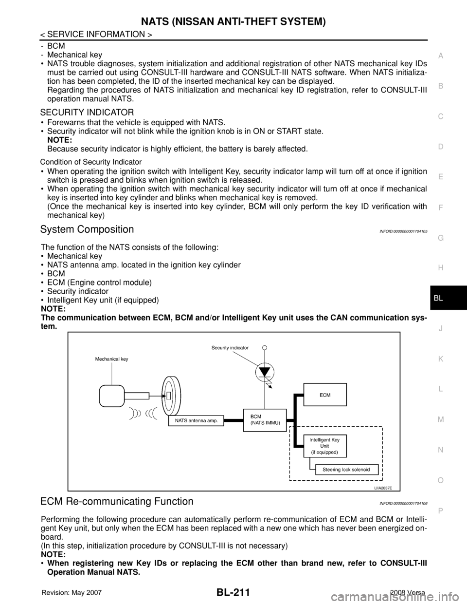
System CompositionINFOID:0000000001704105
The function of the NATS consists of the following:
• Mechanical key
• NATS antenna amp. located in the ignition key cylinder
•BCM
• ECM (Engine control module)
• Security indicator
• Intelligent Key unit (if equipped)
NOTE:
The communication between ECM, BCM and/or Intelligent Key unit uses the CAN communication sys-
tem.
ECM Re-communicating FunctionINFOID:0000000001704106
Performing the following procedure can automatically perform re-communication of ECM and BCM or Intelli-
gent Key unit, but only when the ECM has been replaced with a new one which has never been energized on-
board.
(In this step, initialization procedure by CONSULT-III is not necessary)
NOTE:
•When registering new Key IDs or replacing the ECM other than brand new, refer to CONSULT-III
Operation Manual NATS.
LIIA2637E
Page 646 of 2771

BL-212
< SERVICE INFORMATION >
NATS (NISSAN ANTI-THEFT SYSTEM)
•If multiple keys are attached to the key holder, separate them before work.
•Distinguish keys with unregistered key ID from those with registered ID.
1. Install ECM.
2. Use a registered key (*), turn ignition switch to “ON”.
*: To perform this step, use the key that has been used before to perform ECM replacement.
3. Maintain ignition switch in “ON” position for at least 5 seconds.
4. Turn ignition switch to “OFF”.
5. Start engine.
If engine can be started, procedure is completed.
If engine cannot be started, refer to CONSULT-III Operation Manual NATS and initialize control unit.
Page 650 of 2771

BL-216
< SERVICE INFORMATION >
NATS (NISSAN ANTI-THEFT SYSTEM)
1.STARTING ENGINE
Check if the engine could be started by inserting the mechanical key into the ignition key cylinder and operate
ignition switch.
OK >> System is normal.
NG >> GO TO 2.
2.PERFORM SELF DIAGNOSIS
Perform SELF-DIAGNOSIS “NATS V5.0” using CONSULT-III.
NOTE:
NATS program card is necessary to display the “SELF-DIAGNOSIS”.
No malfunction is detected>>Recheck the starting engine section GO TO 1.
Malfunction related to NATS is detected>>GO TO 3.
Malfunctions related to “DON’T ERASE BEFORE CHECKING ENG DIAG” and NATS are detected>>GO
TO 7.
3.IDENTIFYING NATS MALFUNCTION
Self-diagnosis results referring to NATS, but no information about engine self-diagnosis result is displayed on
CONSULT-III. Refer to BL-217, "
Trouble Diagnosis" .
>> GO TO 4.
4.NATS TROUBLE DIAGNOSIS
Repair NATS (if necessary, perform “C/U INITIALIZATION” with CONSULT-III.)
>> GO TO 5.
5.ERASE SELF-DIAGNOSIS
Erase the record of “SELF-DIAGNOSIS” by using CONSULT-III.
>> GO TO 6.
6.STARTING ENGINE
Check if the engine could be started by inserting the mechanical key into the ignition key cylinder and operate
ignition switch.
NG >> GO TO 2.
OK >> End of inspection.
7.IDENTIFYING NATS AND ENGINE CONTROL MALFUNCTION
NATS malfunction and “DON’T ERASE BEFORE CHECKING ENG DIAG” are displayed on the CONSULT-III
screen.
NOTE:
This indication means that malfunction have been detected in NATS and engine control system.
>> GO TO 8.
8.NATS TROUBLE DIAGNOSIS
Repair NATS according to self-diagnosis results refer to NATS (if necessary, perform “C/U INITIALZATIN” with
CONSULT-III.)
NOTE:
Do not erase “SELF-DIAGNOSIS” by using CONSULT-III.
>> GO TO 9.
Page 651 of 2771
NATS (NISSAN ANTI-THEFT SYSTEM)
BL-217
< SERVICE INFORMATION >
C
D
E
F
G
H
J
K
L
MA
B
BL
N
O
P
9.IDENTIFYING ENGINE CONTROL MALFUNCTION
Check engine “SELF-DIAGNOSIS” records with a generalized program card instead of the NATS program
card.
>> GO TO 10.
10.ENGINE CONTROL SYSTEM TROUBLE DIAGNOSIS
Repair engine control system if engine related malfunction is detected.
With engine diagnostic codes present, refer to EC-9
.
Without engine diagnostic codes present, refer to EC-81
.
NOTE:
If only “NATS MALFUNCTION” is displayed, erase the self-diagnosis results.
>> GO TO 11.
11 .STARTING ENGINE
Check if the engine could be started by inserting the mechanical key into the ignition key cylinder and operate
ignition switch.
OK >> GO TO 12.
NG >> GO TO 2.
12.ERASE SELF-DIAGNOSIS
Erase both NATS and ENGINE "SELF-DIAGNOSIS" records by using CONSULT-III NATS program card and
generalized program card.
>> GO TO 13
13.COMFIRMATION
Perform running test with CONSULT-III in engine “SELF-DIAGNOSIS” mode.
“NO DTC” is displayed>> End of inspection.
Malfunction information is displayed>>GO TO 2.
Trouble DiagnosisINFOID:0000000001704111
SYMPTOM MATRIX CHART 1
Page 767 of 2771
![NISSAN TIIDA 2008 Service Owners Manual BRC-2
< SERVICE INFORMATION >[ABS]
PRECAUTIONS
SERVICE INFORMATION
PRECAUTIONS
Precaution for Supplemental Restraint System (SRS) "AIR BAG" and "SEAT BELT
PRE-TENSIONER"
INFOID:000000 NISSAN TIIDA 2008 Service Owners Manual BRC-2
< SERVICE INFORMATION >[ABS]
PRECAUTIONS
SERVICE INFORMATION
PRECAUTIONS
Precaution for Supplemental Restraint System (SRS) "AIR BAG" and "SEAT BELT
PRE-TENSIONER"
INFOID:000000](/img/5/57399/w960_57399-766.png)
BRC-2
< SERVICE INFORMATION >[ABS]
PRECAUTIONS
SERVICE INFORMATION
PRECAUTIONS
Precaution for Supplemental Restraint System (SRS) "AIR BAG" and "SEAT BELT
PRE-TENSIONER"
INFOID:0000000001703818
The Supplemental Restraint System such as “AIR BAG” and “SEAT BELT PRE-TENSIONER”, used along
with a front seat belt, helps to reduce the risk or severity of injury to the driver and front passenger for certain
types of collision. This system includes seat belt switch inputs and dual stage front air bag modules. The SRS
system uses the seat belt switches to determine the front air bag deployment, and may only deploy one front
air bag, depending on the severity of a collision and whether the front occupants are belted or unbelted.
Information necessary to service the system safely is included in the SRS and SB section of this Service Man-
ual.
WARNING:
• To avoid rendering the SRS inoperative, which could increase the risk of personal injury or death in
the event of a collision which would result in air bag inflation, all maintenance must be performed by
an authorized NISSAN/INFINITI dealer.
• Improper maintenance, including incorrect removal and installation of the SRS, can lead to personal
injury caused by unintentional activation of the system. For removal of Spiral Cable and Air Bag
Module, see the SRS section.
• Do not use electrical test equipment on any circuit related to the SRS unless instructed to in this
Service Manual. SRS wiring harnesses can be identified by yellow and/or orange harnesses or har-
ness connectors.
Precaution for Brake SystemINFOID:0000000001703819
CAUTION:
• Refer to MA-10
for recommended brake fluid.
• Never reuse drained brake fluid.
• Be careful not to splash brake fluid on painted areas; it may cause paint damage. If brake fluid is
splashed on painted areas, wash it away with water immediately.
• To clean or wash all parts of master cylinder and disc brake caliper, use clean brake fluid.
• Never use mineral oils such as gasoline or kerosene. They will ruin rubber parts of the hydraulic sys-
tem.
• Use flare nut wrench when removing and installing brake
tube.
• If a brake fluid leak is found, the part must be disassembled
without fail. Then it has to be replaced with a new one if a
defect exists.
• Turn the ignition switch OFF and remove the connector of the
ABS actuator and electric unit (control unit) or the battery ter-
minal before performing the work.
• Always torque brake lines when installing.
• Burnish the brake contact surfaces after refinishing or replac-
ing rotors, after replacing pads, or if a soft pedal occurs at
very low mileage. Refer to BR-28, "
Brake Burnishing Proce-
dure".
WARNING:
• Clean brake pads and shoes with a waste cloth, then wipe with a dust collector.
Precaution for Brake ControlINFOID:0000000001703821
• During ABS operation, the brake pedal may vibrate lightly and a mechanical noise may be heard. This is
normal.
• Just after starting the vehicle, the brake pedal may vibrate or motor operating noises may be heard from
engine compartment. This is normal due to the self check operation.
• Stopping distance may be longer than that of vehicles without ABS when vehicle drives on rough, gravel, or
snow-covered (fresh, deep snow) roads.
SBR686C