alarm NISSAN TIIDA 2008 Service Owner's Manual
[x] Cancel search | Manufacturer: NISSAN, Model Year: 2008, Model line: TIIDA, Model: NISSAN TIIDA 2008Pages: 2771, PDF Size: 60.61 MB
Page 638 of 2771
BL-204
< SERVICE INFORMATION >
VEHICLE SECURITY (THEFT WARNING) SYSTEM
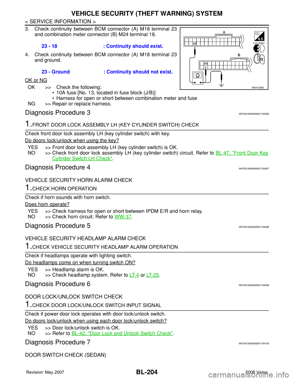
3. Check continuity between BCM connector (A) M18 terminal 23
and combination meter connector (B) M24 terminal 18.
4. Check continuity between BCM connector (A) M18 terminal 23
and ground.
OK or NG
OK >> Check the following:
• 10A fuse [No. 13, located in fuse block (J/B)]
• Harness for open or short between combination meter and fuse
NG >> Repair or replace harness.
Diagnosis Procedure 3INFOID:0000000001704096
1.FRONT DOOR LOCK ASSEMBLY LH (KEY CYLINDER SWITCH) CHECK
Check front door lock assembly LH (key cylinder switch) with key.
Do doors lock/unlock when using the key?
YES >> Front door lock assembly LH (key cylinder switch) is OK.
NO >> Check front door lock assembly LH (key cylinder switch) circuit. Refer to BL-47, "
Front Door Key
Cylinder Switch LH Check".
Diagnosis Procedure 4INFOID:0000000001704097
VEHICLE SECURITY HORN ALARM CHECK
1.CHECK HORN OPERATION
Check if horn sounds with horn switch.
Does horn operate?
YES >> Check harness for open or short between IPDM E/R and horn relay.
NO >> Check horn circuit. Refer to WW-37
.
Diagnosis Procedure 5INFOID:0000000001704098
VEHICLE SECURITY HEADLAMP ALARM CHECK
1.CHECK VEHICLE SECURITY HEADLAMP ALARM OPERATION
Check if headlamps operate with lighting switch.
Do headlamps come on when turning switch ON?
YES >> Headlamp alarm is OK.
NO >> Check headlamp system. Refer to LT- 4
or LT- 2 5.
Diagnosis Procedure 6INFOID:0000000001704099
DOOR LOCK/UNLOCK SWITCH CHECK
1.CHECK DOOR LOCK/UNLOCK SWITCH INPUT SIGNAL
Check if power door lock operates with door lock/unlock switch.
Do doors lock/unlock when using each door lock/unlock switch?
YES >> Door lock/unlock switch is OK.
NO >> Refer to BL-42, "
Door Lock and Unlock Switch Check".
Diagnosis Procedure 7INFOID:0000000001704100
DOOR SWITCH CHECK (SEDAN)
23 - 18 : Continuity should exist.
23 - Ground : Continuity should not exist.
WIIA1269E
Page 2015 of 2771
![NISSAN TIIDA 2008 Service Owners Manual LAN-24
< FUNCTION DIAGNOSIS >[CAN]
CAN COMMUNICATION SYSTEM
Engine coolant temperature signal T R
Engine speed signal T R R
Engine status signal T R
Fuel consumption monitor signal T R
Malfunction ind](/img/5/57399/w960_57399-2014.png "NISSAN TIIDA 2008 Service Owners Manual LAN-24
< FUNCTION DIAGNOSIS >[CAN]
CAN COMMUNICATION SYSTEM
Engine coolant temperature signal T R
Engine speed signal T R R
Engine status signal T R
Fuel consumption monitor signal T R
Malfunction ind")
LAN-24
< FUNCTION DIAGNOSIS >[CAN]
CAN COMMUNICATION SYSTEM
Engine coolant temperature signal T R
Engine speed signal T R R
Engine status signal T R
Fuel consumption monitor signal T R
Malfunction indicator lamp signal T R
Wide open throttle position signal T R R
A/C switch signal R T
Blower fan motor switch signal R T
Buzzer output signalTR
TR
Day time running light request signal
*3TR R
Door lock/unlock status signal T R
Door switch signal T R R R
Front wiper request signal T R
High beam request signal T R R
Horn chirp signal T R
Ignition switch signal T R
Low beam request signal T R
Position lights request signal T R R
Rear window defogger switch signal T R
Sleep/wake up signalRT
TRR R
Theft warning horn request signal T R
Tire pressure signal
*4TR
Trunk open/close status signal T R
Turn indicator signal T R
EPS operation signal R T
EPS warning lamp signal T R
Door lock/unlock/trunk open request signal R T
Hazard request signal R T
Ignition knob switch signal R T
KEY warning lamp signal T R
LOCK warning lamp signal T R
Panic alarm request signal R T
Fuel level sensor signal R T
Overdrive control switch signal T R R
P/N range signal T R
Stop lamp switch signal T R R
Vehicle speed signalRRR T
RRRT R
R
*5R*5T*5
ABS warning lamp signal R TSignal name/Connecting unit
ECM
BCM
EPS
I-KEY
M&A
ABS
TCM
*1
TCM
*2
IPDM-E
Page 2457 of 2771

PG-24
< SERVICE INFORMATION >
IPDM E/R (INTELLIGENT POWER DISTRIBUTION MODULE ENGINE ROOM)
24 Y Cooling fan relay-3 Output —Conditions correct for cooling
fan high operationBattery voltage
Conditions not correct for
cooling fan high operation0V
26 OTail lamp relay (park-
ing lamps)Output — Lighting switch in 2nd position Battery voltage
27 BRTail lamp relay (park-
ing lamps)Output — Lighting switch in 2nd position Battery voltage
28 GRTail lamp relay (park-
ing lamps)Output — Lighting switch in 2nd position Battery voltage
29 PTail lamp relay (park-
ing lamps)Output — Lighting switch in 2nd position Battery voltage
30
(A/T
only)R Fuse 54 Output —Ignition switch ON or START Battery voltage
Ignition switch OFF or ACC 0V
31 O Fuse 55 Output —Ignition switch ON or START Battery voltage
Ignition switch OFF or ACC 0V
32 LWiper high speed sig-
nalOutputON or
STARTWiper switchOFF, LO, INT 0V
HI Battery voltage
33 YWiper low speed sig-
nalOutputON or
STARTWiper switchOFF 0V
LO or INT Battery voltage
35 BRStarter relay (inhibit
switch)InputON or
STARTSelector lever in "P" or "N"
(CVT or A/T) or clutch pedal
depressed (M/T)Battery voltage
Selector lever any other posi-
tion (CVT or A/T) or clutch
pedal released (M/T)0V
36 BR Fuel pump relay Output —Ignition switch ON or START Battery voltage
Ignition switch OFF or ACC 0V
37 G Oil pressure switch InputON or
STARTEngine running and oil pres-
sure within specificationBattery voltage
Engine not running or oil pres-
sure below specification0V
38 R Wiper auto stop signal InputON or
STARTWipers not in park position Battery voltage
Wipers in park position 0V
39 B Ground Input — — 0V
40 P CAN-L — ON — —
41 L CAN-H — ON — —
45 R Horn relay control Input —Horn switch PUSHED, alarm
switch activated or door lock/
unlock is confirmed when op-
erating lock system via the
keyfob0V
Horn switch released, alarm
not active, keyfob not activeBattery voltage
46 YThrottle control motor
relay controlInput —Ignition switch ON or START 0V
Ignition switch OFF or ACC Battery voltage
47 GRFuel pump relay con-
trolInput —
Ignition switch ON or START 0V
Ignition switch OFF or ACC Battery voltage Te r m i n a lWire
colorSignal nameSignal
input/
outputMeasuring condition
Reference value
(Approx.) Ignition
switchOperation or condition