height NISSAN TIIDA 2008 Service Owner's Guide
[x] Cancel search | Manufacturer: NISSAN, Model Year: 2008, Model line: TIIDA, Model: NISSAN TIIDA 2008Pages: 2771, PDF Size: 60.61 MB
Page 1778 of 2771
CYLINDER BLOCK
EM-101
< SERVICE INFORMATION >
C
D
E
F
G
H
I
J
K
L
MA
EM
N
P O
• If clearance exceeds the limit, select proper main bearing according to main bearing inner diameter and
crankshaft main journal diameter to obtain specified bearing oil clearance. Refer to EM-85, "
How to Select
Piston and Bearing".
Method of Using Plastigage
• Remove engine oil and dust on crankshaft main journal and the surfaces of each bearing completely.
• Cut a plastigage slightly shorter than the bearing width, and place it in crankshaft axial direction, avoiding oil
holes.
• Install main bearings to cylinder block and main bearing cap, and tighten main bearing cap bolts to the spec-
ified torque. Refer to EM-77, "
Disassembly and Assembly" for the tightening procedure.
CAUTION:
Never rotate crankshaft.
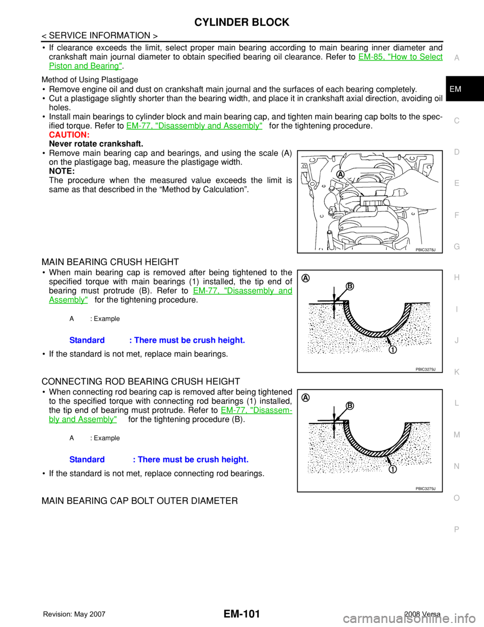
• Remove main bearing cap and bearings, and using the scale (A)
on the plastigage bag, measure the plastigage width.
NOTE:
The procedure when the measured value exceeds the limit is
same as that described in the “Method by Calculation”.
MAIN BEARING CRUSH HEIGHT
• When main bearing cap is removed after being tightened to the
specified torque with main bearings (1) installed, the tip end of
bearing must protrude (B). Refer to EM-77, "
Disassembly and
Assembly" for the tightening procedure.
• If the standard is not met, replace main bearings.
CONNECTING ROD BEARING CRUSH HEIGHT
• When connecting rod bearing cap is removed after being tightened
to the specified torque with connecting rod bearings (1) installed,
the tip end of bearing must protrude. Refer to EM-77, "
Disassem-
bly and Assembly" for the tightening procedure (B).
• If the standard is not met, replace connecting rod bearings.
MAIN BEARING CAP BOLT OUTER DIAMETER
PBIC3278J
A : Example
Standard : There must be crush height.
PBIC3279J
A : Example
Standard : There must be crush height.
PBIC3279J
Page 1782 of 2771
SERVICE DATA AND SPECIFICATIONS (SDS)
EM-105
< SERVICE INFORMATION >
C
D
E
F
G
H
I
J
K
L
MA
EM
N
P O
Unit: mm (in)
VA LV E
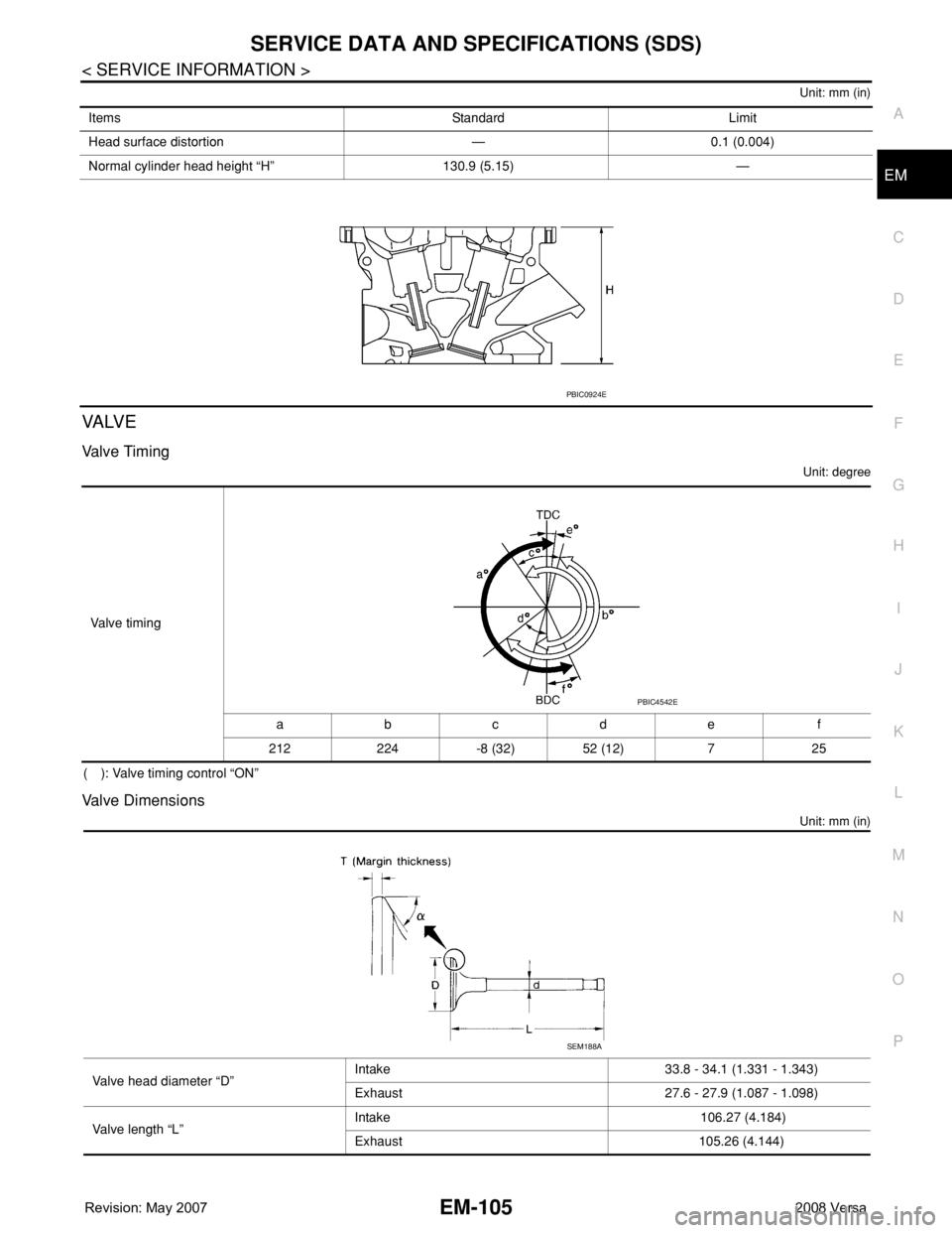
Va l v e Ti m i n g
Unit: degree
( ): Valve timing control “ON”
Valve Dimensions
Unit: mm (in)
Items Standard Limit
Head surface distortion — 0.1 (0.004)
Normal cylinder head height “H” 130.9 (5.15) —
PBIC0924E
Valve timing
abcde f
212 224 -8 (32) 52 (12) 7 25
PBIC4542E
Valve head diameter “D”Intake 33.8 - 34.1 (1.331 - 1.343)
Exhaust 27.6 - 27.9 (1.087 - 1.098)
Valve length “L”Intake 106.27 (4.184)
Exhaust 105.26 (4.144)
SEM188A
Page 1784 of 2771
SERVICE DATA AND SPECIFICATIONS (SDS)
EM-107
< SERVICE INFORMATION >
C
D
E
F
G
H
I
J
K
L
MA
EM
N
P O Va l v e Sp r i n g
Valve Lifter
Unit: mm (in)
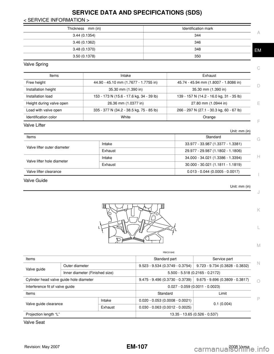
Valve Guide
Unit: mm (in)
Valve Seat
3.44 (0.1354) 344
3.46 (0.1362) 346
3.48 (0.1370) 348
3.50 (0.1378) 350 Thickness mm (in) Identification mark
Items Intake Exhaust
Free height 44.90 - 45.10 mm (1.7677 - 1.7755 in) 45.74 - 45.94 mm (1.8007 - 1.8086 in)
Installation height 35.30 mm (1.390 in) 35.30 mm (1.390 in)
Installation load 153 - 173 N (15.6 - 17.6 kg, 34 - 39 lb) 139 - 157 N (14.2 - 16.0 kg, 31 - 35 lb)
Height during valve open 26.36 mm (1.0377 in) 27.80 mm (1.0944 in)
Load with valve open 335 - 377 N (34.2 - 38.5 kg, 75 - 85 lb) 266 - 297 N (27.1 - 30.3 kg, 60 - 67 lb)
Identification color White Orange
ItemsStandard
Valve lifter outer diameterIntake 33.977 - 33.987 (1.3377 - 1.3381)
Exhaust 29.977 - 29.987 (1.1802 - 1.1806)
Valve lifter hole diameterIntake 34.000 - 34.021 (1.3386 - 1.3394)
Exhaust 30.000 - 30.021 (1.1811 - 1.1819)
Valve lifter clearance0.013 - 0.044 (0.0005 - 0.0017)
Items Standard part Service part
Va l v e g u i d eOuter diameter 9.523 - 9.534 (0.3749 - 0.3754) 9.723 - 9.734 (0.3828 - 0.3832)
Inner diameter (Finished size) 5.500 - 5.518 (0.2165 - 0.2172)
Cylinder head valve guide hole diameter 9.475 - 9.496 (0.3730 - 0.3739) 9.675 - 9.696 (0.3809 - 0.3817)
Interference fit of valve guide 0.027 - 0.059 (0.0011 - 0.0023)
ItemsStandard Limit
Valve guide clearanceIntake 0.020 - 0.053 (0.0008 - 0.0021)
0.1 (0.004)
Exhaust 0.030 - 0.063 (0.0012 - 0.0025)
Projection length “L” 13.35 - 13.65 (0.526 - 0.537)
PBIC0184E
Page 1785 of 2771
EM-108
< SERVICE INFORMATION >
SERVICE DATA AND SPECIFICATIONS (SDS)
Unit: mm (in)
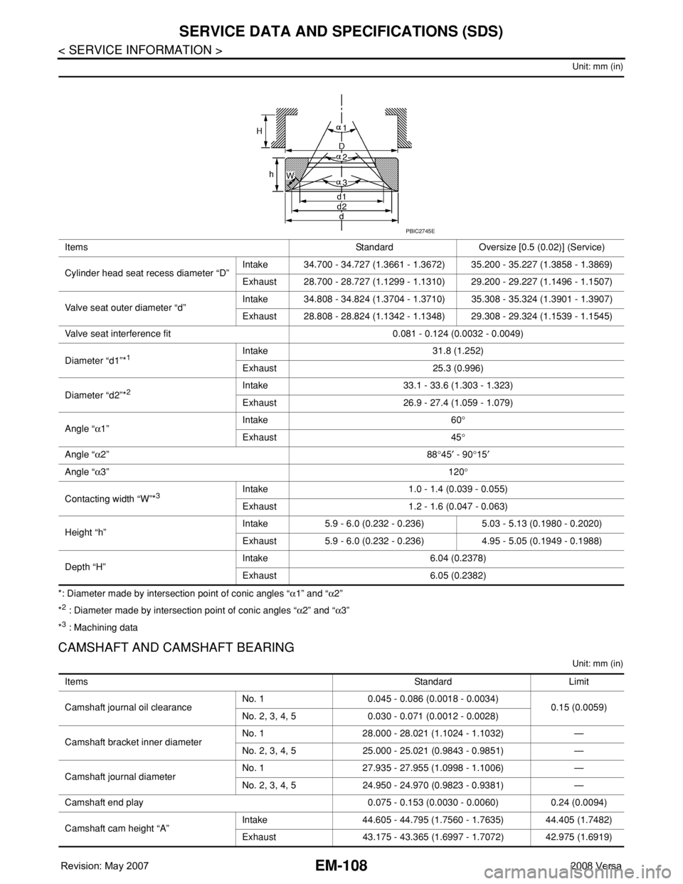
*: Diameter made by intersection point of conic angles “α1” and “α2”
*
2 : Diameter made by intersection point of conic angles “α2” and “α3”
*
3 : Machining data
CAMSHAFT AND CAMSHAFT BEARING
Unit: mm (in)
Items Standard Oversize [0.5 (0.02)] (Service)
Cylinder head seat recess diameter “D”Intake 34.700 - 34.727 (1.3661 - 1.3672) 35.200 - 35.227 (1.3858 - 1.3869)
Exhaust 28.700 - 28.727 (1.1299 - 1.1310) 29.200 - 29.227 (1.1496 - 1.1507)
Valve seat outer diameter “d”Intake 34.808 - 34.824 (1.3704 - 1.3710) 35.308 - 35.324 (1.3901 - 1.3907)
Exhaust 28.808 - 28.824 (1.1342 - 1.1348) 29.308 - 29.324 (1.1539 - 1.1545)
Valve seat interference fit 0.081 - 0.124 (0.0032 - 0.0049)
Diameter “d1”*
1Intake 31.8 (1.252)
Exhaust 25.3 (0.996)
Diameter “d2”*
2Intake 33.1 - 33.6 (1.303 - 1.323)
Exhaust 26.9 - 27.4 (1.059 - 1.079)
Angle “α1”Intake 60°
Exhaust 45°
Angle “α2”88°45′ - 90°15′
Angle “α3”120°
Contacting width “W”*
3Intake 1.0 - 1.4 (0.039 - 0.055)
Exhaust 1.2 - 1.6 (0.047 - 0.063)
Height “h”Intake 5.9 - 6.0 (0.232 - 0.236) 5.03 - 5.13 (0.1980 - 0.2020)
Exhaust 5.9 - 6.0 (0.232 - 0.236) 4.95 - 5.05 (0.1949 - 0.1988)
Depth “H”Intake 6.04 (0.2378)
Exhaust 6.05 (0.2382)
PBIC2745E
ItemsStandard Limit
Camshaft journal oil clearanceNo. 1 0.045 - 0.086 (0.0018 - 0.0034)
0.15 (0.0059)
No. 2, 3, 4, 5 0.030 - 0.071 (0.0012 - 0.0028)
Camshaft bracket inner diameterNo. 1 28.000 - 28.021 (1.1024 - 1.1032) —
No. 2, 3, 4, 5 25.000 - 25.021 (0.9843 - 0.9851) —
Camshaft journal diameterNo. 1 27.935 - 27.955 (1.0998 - 1.1006) —
No. 2, 3, 4, 5 24.950 - 24.970 (0.9823 - 0.9381) —
Camshaft end play 0.075 - 0.153 (0.0030 - 0.0060) 0.24 (0.0094)
Camshaft cam height “A”Intake 44.605 - 44.795 (1.7560 - 1.7635) 44.405 (1.7482)
Exhaust 43.175 - 43.365 (1.6997 - 1.7072) 42.975 (1.6919)
Page 1787 of 2771
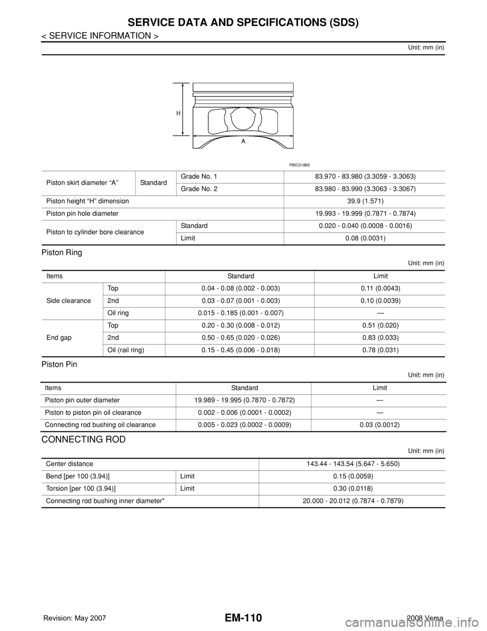
EM-110
< SERVICE INFORMATION >
SERVICE DATA AND SPECIFICATIONS (SDS)
Unit: mm (in)
Piston Ring
Unit: mm (in)
Piston Pin
Unit: mm (in)
CONNECTING ROD
Unit: mm (in)
Piston skirt diameter “A” StandardGrade No. 1 83.970 - 83.980 (3.3059 - 3.3063)
Grade No. 2 83.980 - 83.990 (3.3063 - 3.3067)
Piston height “H” dimension39.9 (1.571)
Piston pin hole diameter 19.993 - 19.999 (0.7871 - 0.7874)
Piston to cylinder bore clearanceStandard 0.020 - 0.040 (0.0008 - 0.0016)
Limit 0.08 (0.0031)
PBIC0188E
Items Standard Limit
Side clearanceTop 0.04 - 0.08 (0.002 - 0.003) 0.11 (0.0043)
2nd 0.03 - 0.07 (0.001 - 0.003) 0.10 (0.0039)
Oil ring 0.015 - 0.185 (0.001 - 0.007) —
End gapTop 0.20 - 0.30 (0.008 - 0.012) 0.51 (0.020)
2nd 0.50 - 0.65 (0.020 - 0.026) 0.83 (0.033)
Oil (rail ring) 0.15 - 0.45 (0.006 - 0.018) 0.78 (0.031)
Items Standard Limit
Piston pin outer diameter 19.989 - 19.995 (0.7870 - 0.7872) —
Piston to piston pin oil clearance 0.002 - 0.006 (0.0001 - 0.0002) —
Connecting rod bushing oil clearance 0.005 - 0.023 (0.0002 - 0.0009) 0.03 (0.0012)
Center distance 143.44 - 143.54 (5.647 - 5.650)
Bend [per 100 (3.94)] Limit 0.15 (0.0059)
Torsion [per 100 (3.94)] Limit 0.30 (0.0118)
Connecting rod bushing inner diameter* 20.000 - 20.012 (0.7874 - 0.7879)
Page 1796 of 2771
EXHAUST SYSTEM
EX-5
< SERVICE INFORMATION >
C
D
E
F
G
H
I
J
K
L
MA
EX
N
P O
• Be sure to use genuine NISSAN exhaust system parts or equivalents which are specially designed
for heat resistance, corrosion resistance and shape.
• Perform the operation with the exhaust system fully cooled down because the system will be hot
just after the engine stops.
• Be careful not to cut your hand on heat insulator edge.
1. Disconnect harness connector of heated oxygen sensor 2.
• Using Tool, remove heated oxygen sensor 2.
CAUTION:
Be careful not to damage heated oxygen sensor 2.
a.2. Disconnect each joint and mounting rubber.
INSTALLATION
Installation is in the reverse order of removal.
CAUTION:
• Always replace exhaust gaskets and seal bearings with new ones when installing.
• Discard any heated oxygen sensor 2 which has been dropped from a height of more than 0.5 m (19.7
in) onto a hard surface such as a concrete floor; use a new one.
• Before installing a new heated oxygen sensor 2, clean exhaust system threads using the heated oxy-
gen sensor thread cleaner and apply anti-seize lubricant (commercial service tool).
• Do not over tighten heated oxygen sensor 2. Doing so may cause damage to the heated oxygen sen-
sor 2, resulting in the “MIL” coming on.
• Remove deposits from the sealing surface of each connection. Connect them securely to avoid
exhaust leakage.
• Temporarily tighten nuts on the exhaust manifold side and bolts on the vehicle side. Check each part
for unusual interference, and then tighten them to the specified torque.
• When installing each mounting rubber, avoid twisting or unusual extension in up/down and right/left
directions.
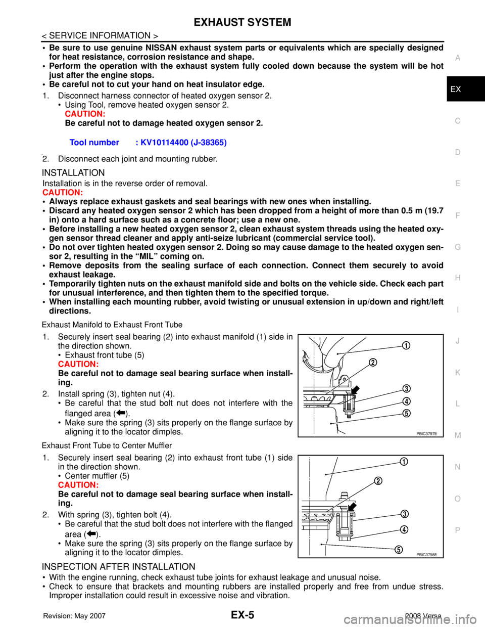
Exhaust Manifold to Exhaust Front Tube
1. Securely insert seal bearing (2) into exhaust manifold (1) side in
the direction shown.
• Exhaust front tube (5)
CAUTION:
Be careful not to damage seal bearing surface when install-
ing.
2. Install spring (3), tighten nut (4).
• Be careful that the stud bolt nut does not interfere with the
flanged area ( ).
• Make sure the spring (3) sits properly on the flange surface by
aligning it to the locator dimples.
Exhaust Front Tube to Center Muffler
1. Securely insert seal bearing (2) into exhaust front tube (1) side
in the direction shown.
• Center muffler (5)
CAUTION:
Be careful not to damage seal bearing surface when install-
ing.
2. With spring (3), tighten bolt (4).
• Be careful that the stud bolt does not interfere with the flanged
area ( ).
• Make sure the spring (3) sits properly on the flange surface by
aligning it to the locator dimples.
INSPECTION AFTER INSTALLATION
• With the engine running, check exhaust tube joints for exhaust leakage and unusual noise.
• Check to ensure that brackets and mounting rubbers are installed properly and free from undue stress.
Improper installation could result in excessive noise and vibration.Tool number : KV10114400 (J-38365)
PBIC3797E
PBIC3798E
Page 1835 of 2771
FSU-1
SUSPENSION
C
D
F
G
H
I
J
K
L
M
SECTION FSU
A
B
FSU
N
O
PCONTENTS
FRONT SUSPENSION
SERVICE INFORMATION ............................2
PRECAUTIONS ...................................................2
Precaution for Supplemental Restraint System
(SRS) "AIR BAG" and "SEAT BELT PRE-TEN-
SIONER" ...................................................................
2
Precaution for Procedure without Cowl Top Cover ......2
Cautions ....................................................................2
PREPARATION ...................................................3
Special Service Tool .................................................3
Commercial Service Tool ..........................................4
NOISE, VIBRATION AND HARSHNESS
(NVH) TROUBLESHOOTING .............................
5
NVH Troubleshooting Chart ......................................5
FRONT SUSPENSION ASSEMBLY ...................6
On-Vehicle Inspection and Service ...........................6
Wheel Alignment Inspection .....................................6
Component ...............................................................9
Removal and Installation .........................................10
COIL SPRING AND STRUT ..............................11
Removal and Installation .........................................11
Disassembly and Assembly .....................................11
TRANSVERSE LINK .........................................14
Removal and Installation .........................................14
STABILIZER BAR .............................................15
Removal and Installation .........................................15
SERVICE DATA AND SPECIFICATIONS
(SDS) .................................................................
16
Wheel Alignment (Unladen*) ...................................16
Ball Joint ..................................................................16
Wheelarch Height (Unladen*) ..................................17
Page 1840 of 2771
FSU-6
< SERVICE INFORMATION >
FRONT SUSPENSION ASSEMBLY
FRONT SUSPENSION ASSEMBLY
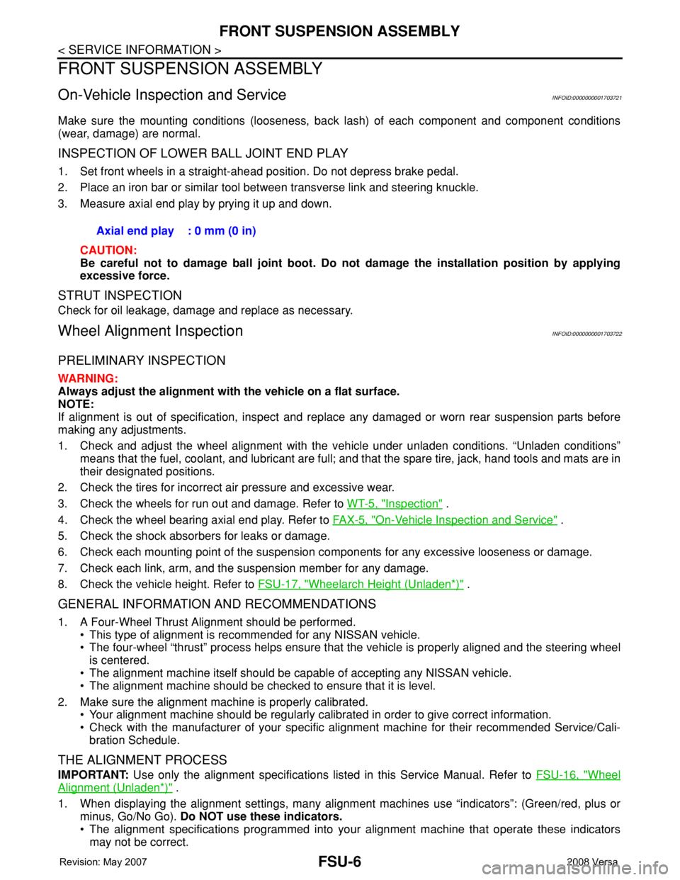
On-Vehicle Inspection and ServiceINFOID:0000000001703721
Make sure the mounting conditions (looseness, back lash) of each component and component conditions
(wear, damage) are normal.
INSPECTION OF LOWER BALL JOINT END PLAY
1. Set front wheels in a straight-ahead position. Do not depress brake pedal.
2. Place an iron bar or similar tool between transverse link and steering knuckle.
3. Measure axial end play by prying it up and down.
CAUTION:
Be careful not to damage ball joint boot. Do not damage the installation position by applying
excessive force.
STRUT INSPECTION
Check for oil leakage, damage and replace as necessary.
Wheel Alignment InspectionINFOID:0000000001703722
PRELIMINARY INSPECTION
WARNING:
Always adjust the alignment with the vehicle on a flat surface.
NOTE:
If alignment is out of specification, inspect and replace any damaged or worn rear suspension parts before
making any adjustments.
1. Check and adjust the wheel alignment with the vehicle under unladen conditions. “Unladen conditions”
means that the fuel, coolant, and lubricant are full; and that the spare tire, jack, hand tools and mats are in
their designated positions.
2. Check the tires for incorrect air pressure and excessive wear.
3. Check the wheels for run out and damage. Refer to WT-5, "
Inspection" .
4. Check the wheel bearing axial end play. Refer to FA X - 5 , "
On-Vehicle Inspection and Service" .
5. Check the shock absorbers for leaks or damage.
6. Check each mounting point of the suspension components for any excessive looseness or damage.
7. Check each link, arm, and the suspension member for any damage.
8. Check the vehicle height. Refer to FSU-17, "
Wheelarch Height (Unladen*)" .
GENERAL INFORMATION AND RECOMMENDATIONS
1. A Four-Wheel Thrust Alignment should be performed.
• This type of alignment is recommended for any NISSAN vehicle.
• The four-wheel “thrust” process helps ensure that the vehicle is properly aligned and the steering wheel
is centered.
• The alignment machine itself should be capable of accepting any NISSAN vehicle.
• The alignment machine should be checked to ensure that it is level.
2. Make sure the alignment machine is properly calibrated.
• Your alignment machine should be regularly calibrated in order to give correct information.
• Check with the manufacturer of your specific alignment machine for their recommended Service/Cali-
bration Schedule.
THE ALIGNMENT PROCESS
IMPORTANT: Use only the alignment specifications listed in this Service Manual. Refer to FSU-16, "Wheel
Alignment (Unladen*)" .
1. When displaying the alignment settings, many alignment machines use “indicators”: (Green/red, plus or
minus, Go/No Go). Do NOT use these indicators.
• The alignment specifications programmed into your alignment machine that operate these indicators
may not be correct.Axial end play : 0 mm (0 in)
Page 1841 of 2771
FRONT SUSPENSION ASSEMBLY
FSU-7
< SERVICE INFORMATION >
C
D
F
G
H
I
J
K
L
MA
B
FSU
N
O
P
• This may result in an ERROR.
2. Some newer alignment machines are equipped with an optional “Rolling Compensation” method to “com-
pensate” the sensors (alignment targets or head units). Do NOT use this “Rolling Compensation”
method.
• Use the “Jacking Compensation” method. After installing the alignment targets or head units, raise the
vehicle and rotate the wheels 1/2 turn both ways.
• See Instructions in the alignment machine you are using for more information.
CAMBER, CASTER AND KINGPIN INCLINATION ANGLES INSPECTION
• Camber, caster, kingpin inclination angles cannot be adjusted.
• Before inspection, mount front wheels onto turning radius gauge. Mount rear wheels onto a stand that has
same height so vehicle will remain horizontal.
Using a CCK Gauge
Install the CCK gauge attachment [SST: KV991040S0] with the following procedure on wheel, then measure
wheel alignment.
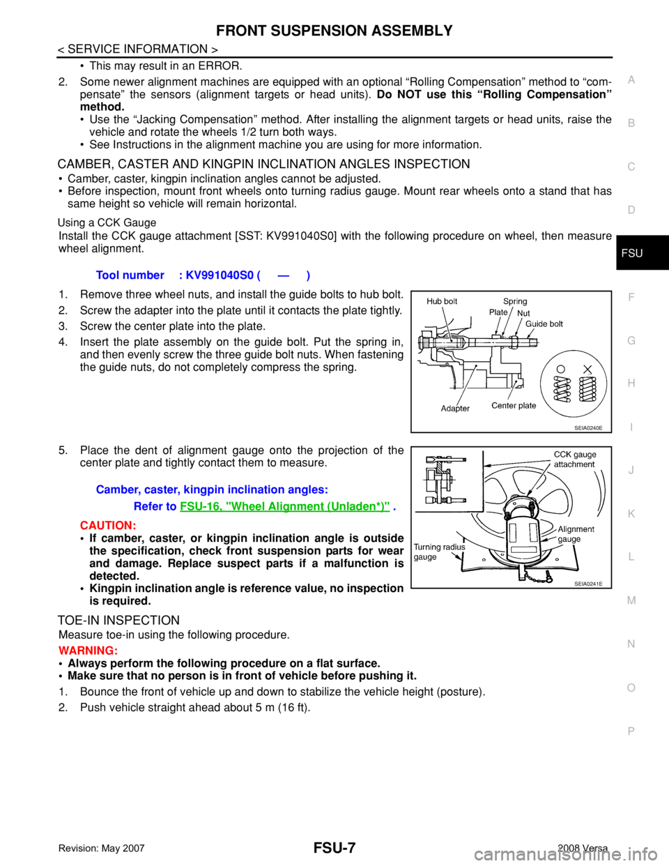
1. Remove three wheel nuts, and install the guide bolts to hub bolt.
2. Screw the adapter into the plate until it contacts the plate tightly.
3. Screw the center plate into the plate.
4. Insert the plate assembly on the guide bolt. Put the spring in,
and then evenly screw the three guide bolt nuts. When fastening
the guide nuts, do not completely compress the spring.
5. Place the dent of alignment gauge onto the projection of the
center plate and tightly contact them to measure.
CAUTION:
• If camber, caster, or kingpin inclination angle is outside
the specification, check front suspension parts for wear
and damage. Replace suspect parts if a malfunction is
detected.
• Kingpin inclination angle is reference value, no inspection
is required.
TOE-IN INSPECTION
Measure toe-in using the following procedure.
WARNING:
• Always perform the following procedure on a flat surface.
• Make sure that no person is in front of vehicle before pushing it.
1. Bounce the front of vehicle up and down to stabilize the vehicle height (posture).
2. Push vehicle straight ahead about 5 m (16 ft).Tool number : KV991040S0 ( — )
SEIA0240E
Camber, caster, kingpin inclination angles:
Refer to FSU-16, "
Wheel Alignment (Unladen*)" .
SEIA0241E
Page 1842 of 2771
FSU-8
< SERVICE INFORMATION >
FRONT SUSPENSION ASSEMBLY
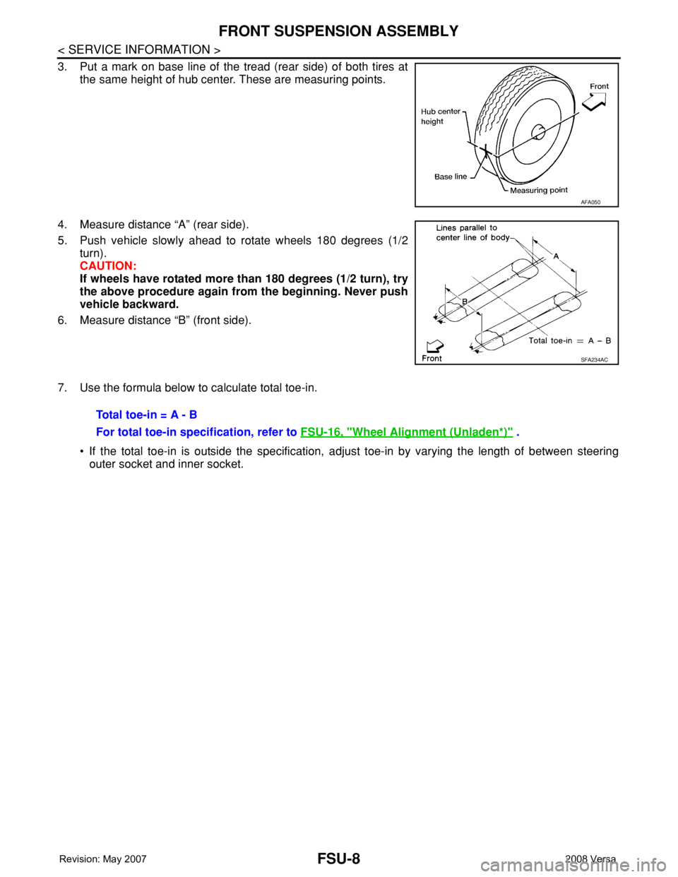
3. Put a mark on base line of the tread (rear side) of both tires at
the same height of hub center. These are measuring points.
4. Measure distance “A” (rear side).
5. Push vehicle slowly ahead to rotate wheels 180 degrees (1/2
turn).
CAUTION:
If wheels have rotated more than 180 degrees (1/2 turn), try
the above procedure again from the beginning. Never push
vehicle backward.
6. Measure distance “B” (front side).
7. Use the formula below to calculate total toe-in.
• If the total toe-in is outside the specification, adjust toe-in by varying the length of between steering
outer socket and inner socket.
AFA050
SFA234AC
Total toe-in = A - B
For total toe-in specification, refer to FSU-16, "
Wheel Alignment (Unladen*)" .