height NISSAN TIIDA 2008 Service Service Manual
[x] Cancel search | Manufacturer: NISSAN, Model Year: 2008, Model line: TIIDA, Model: NISSAN TIIDA 2008Pages: 2771, PDF Size: 60.61 MB
Page 1851 of 2771
SERVICE DATA AND SPECIFICATIONS (SDS)
FSU-17
< SERVICE INFORMATION >
C
D
F
G
H
I
J
K
L
MA
B
FSU
N
O
P
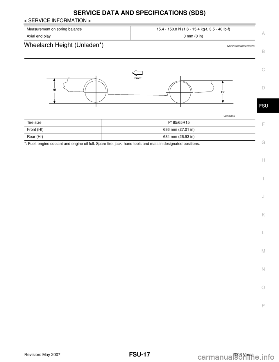
Wheelarch Height (Unladen*)INFOID:0000000001703731
*: Fuel, engine coolant and engine oil full. Spare tire, jack, hand tools and mats in designated positions.Measurement on spring balance 15.4 - 150.8 N (1.6 - 15.4 kg-f, 3.5 - 40 lb-f)
Axial end play0 mm (0 in)
Tire sizeP185/65R15
Front (Hf) 686 mm (27.01 in)
Rear (Hr) 684 mm (26.93 in)
LEIA0085E
Page 1897 of 2771
GI-46
< SERVICE INFORMATION >
IDENTIFICATION INFORMATION
CVT NUMBER
DimensionsINFOID:0000000001702457
Unit: mm (in)
Wheels & TiresINFOID:0000000001702458
LAIA0074E
Overall length Hatchback: 4,295 (169.1) Sedan: 4470 (176)
Overall width1,694.2 (66.7)
Overall height1,534.1 (60.4)
Front tread1,480 (58.3)
Rear tread1,485 (58.5)
Wheelbase2,599.9 (102.4)
Road wheel
Size15 x 5.5 JJ
Offset mm (in) 40 (1.57)
Tire size
Conventional185/65 R15
Spar eT125/70D15
Page 2520 of 2771
PS-14
< SERVICE INFORMATION >
POWER STEERING GEAR
3. Remove inner socket from rack assembly while holding the flat portion of the rack next to the inner socket
using a suitable tool.
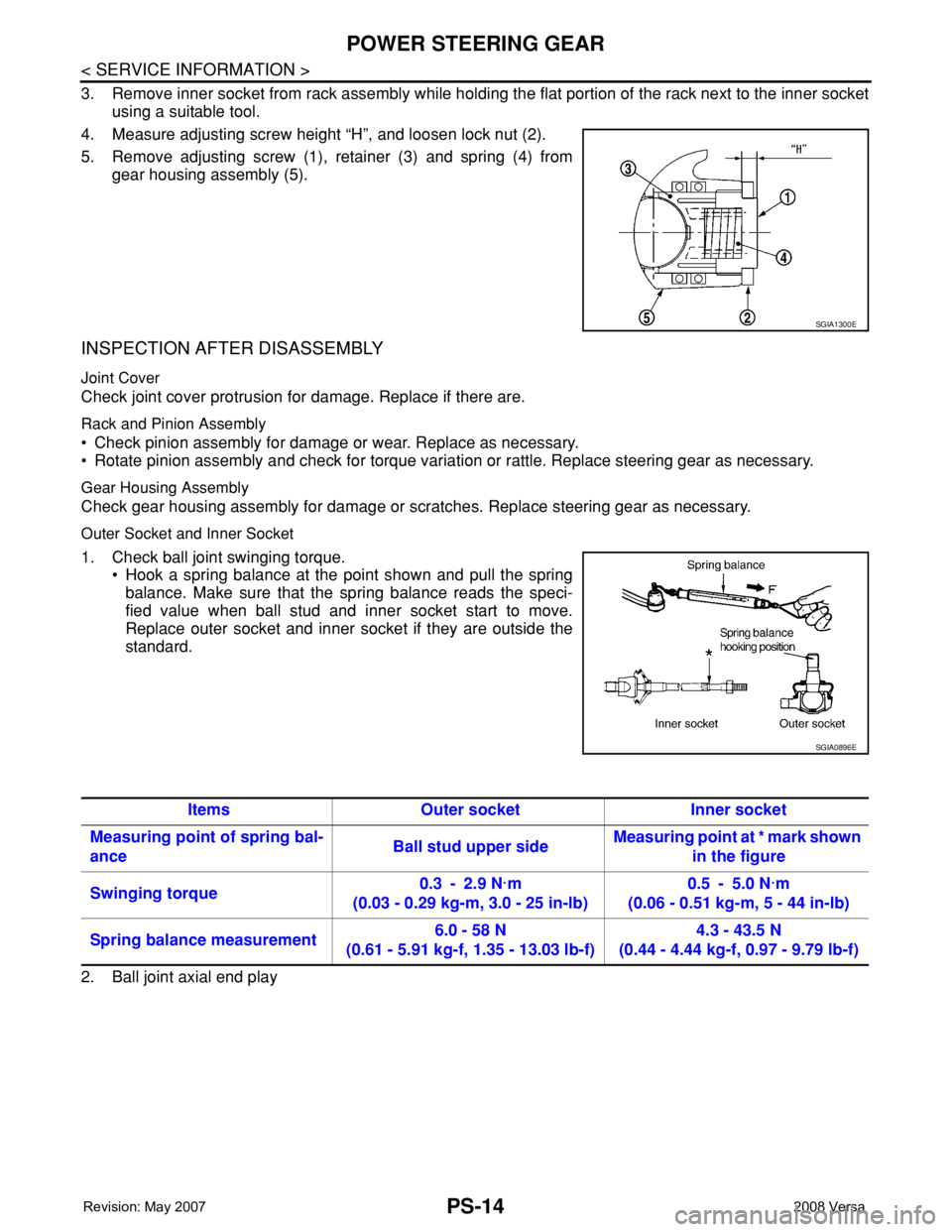
4. Measure adjusting screw height “H”, and loosen lock nut (2).
5. Remove adjusting screw (1), retainer (3) and spring (4) from
gear housing assembly (5).
INSPECTION AFTER DISASSEMBLY
Joint Cover
Check joint cover protrusion for damage. Replace if there are.
Rack and Pinion Assembly
• Check pinion assembly for damage or wear. Replace as necessary.
• Rotate pinion assembly and check for torque variation or rattle. Replace steering gear as necessary.
Gear Housing Assembly
Check gear housing assembly for damage or scratches. Replace steering gear as necessary.
Outer Socket and Inner Socket
1. Check ball joint swinging torque.
• Hook a spring balance at the point shown and pull the spring
balance. Make sure that the spring balance reads the speci-
fied value when ball stud and inner socket start to move.
Replace outer socket and inner socket if they are outside the
standard.
2. Ball joint axial end play
SGIA1300E
SGIA0896E
Items Outer socket Inner socket
Measuring point of spring bal-
anceBall stud upper sideMeasuring point at * mark shown
in the figure
Swinging torque0.3 - 2.9 N·m
(0.03 - 0.29 kg-m, 3.0 - 25 in-lb)0.5 - 5.0 N·m
(0.06 - 0.51 kg-m, 5 - 44 in-lb)
Spring balance measurement6.0 - 58 N
(0.61 - 5.91 kg-f, 1.35 - 13.03 lb-f)4.3 - 43.5 N
(0.44 - 4.44 kg-f, 0.97 - 9.79 lb-f)
Page 2521 of 2771
POWER STEERING GEAR
PS-15
< SERVICE INFORMATION >
C
D
E
F
H
I
J
K
L
MA
B
PS
N
O
P
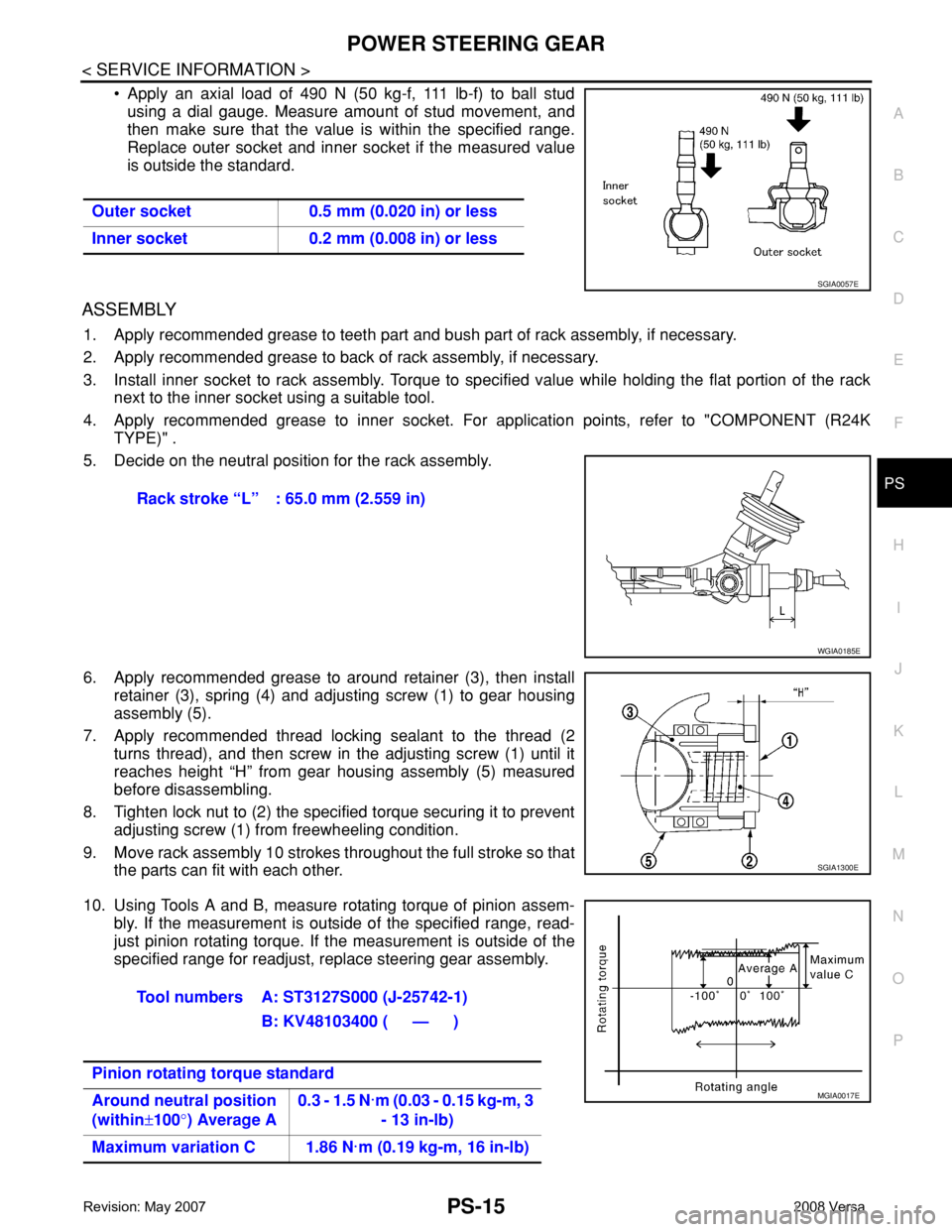
• Apply an axial load of 490 N (50 kg-f, 111 lb-f) to ball stud
using a dial gauge. Measure amount of stud movement, and
then make sure that the value is within the specified range.
Replace outer socket and inner socket if the measured value
is outside the standard.
ASSEMBLY
1. Apply recommended grease to teeth part and bush part of rack assembly, if necessary.
2. Apply recommended grease to back of rack assembly, if necessary.
3. Install inner socket to rack assembly. Torque to specified value while holding the flat portion of the rack
next to the inner socket using a suitable tool.
4. Apply recommended grease to inner socket. For application points, refer to "COMPONENT (R24K
TYPE)" .
5. Decide on the neutral position for the rack assembly.
6. Apply recommended grease to around retainer (3), then install
retainer (3), spring (4) and adjusting screw (1) to gear housing
assembly (5).
7. Apply recommended thread locking sealant to the thread (2
turns thread), and then screw in the adjusting screw (1) until it
reaches height “H” from gear housing assembly (5) measured
before disassembling.
8. Tighten lock nut to (2) the specified torque securing it to prevent
adjusting screw (1) from freewheeling condition.
9. Move rack assembly 10 strokes throughout the full stroke so that
the parts can fit with each other.
10. Using Tools A and B, measure rotating torque of pinion assem-
bly. If the measurement is outside of the specified range, read-
just pinion rotating torque. If the measurement is outside of the
specified range for readjust, replace steering gear assembly. Outer socket 0.5 mm (0.020 in) or less
Inner socket 0.2 mm (0.008 in) or less
SGIA0057E
Rack stroke “L” : 65.0 mm (2.559 in)
WGIA0185E
SGIA1300E
Tool numbers A: ST3127S000 (J-25742-1)
B: KV48103400 ( — )
Pinion rotating torque standard
Around neutral position
(within±100°) Average A0.3 - 1.5 N·m (0.03 - 0.15 kg-m, 3
- 13 in-lb)
Maximum variation C 1.86 N·m (0.19 kg-m, 16 in-lb)
MGIA0017E
Page 2557 of 2771
SUNROOF
RF-27
< ON-VEHICLE REPAIR >
C
D
E
F
G
H
J
K
L
MA
B
RF
N
O
P
HEIGHT ADJUSTMENT
1. Tilt up glass lid.
2. Loosen glass lid bolts, then tilt down glass lid.
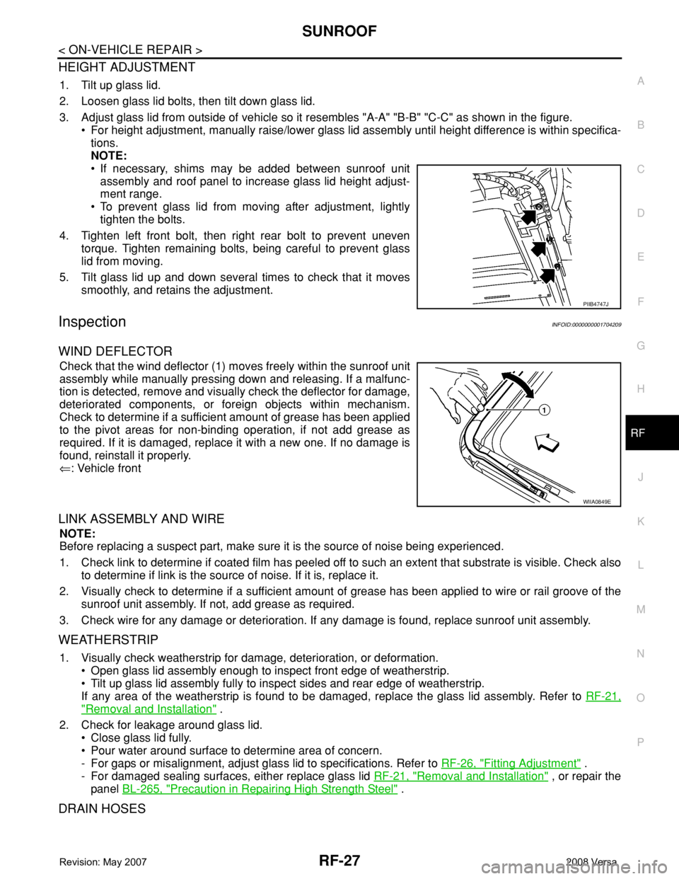
3. Adjust glass lid from outside of vehicle so it resembles "A-A" "B-B" "C-C" as shown in the figure.
• For height adjustment, manually raise/lower glass lid assembly until height difference is within specifica-
tions.
NOTE:
• If necessary, shims may be added between sunroof unit
assembly and roof panel to increase glass lid height adjust-
ment range.
• To prevent glass lid from moving after adjustment, lightly
tighten the bolts.
4. Tighten left front bolt, then right rear bolt to prevent uneven
torque. Tighten remaining bolts, being careful to prevent glass
lid from moving.
5. Tilt glass lid up and down several times to check that it moves
smoothly, and retains the adjustment.
InspectionINFOID:0000000001704209
WIND DEFLECTOR
Check that the wind deflector (1) moves freely within the sunroof unit
assembly while manually pressing down and releasing. If a malfunc-
tion is detected, remove and visually check the deflector for damage,
deteriorated components, or foreign objects within mechanism.
Check to determine if a sufficient amount of grease has been applied
to the pivot areas for non-binding operation, if not add grease as
required. If it is damaged, replace it with a new one. If no damage is
found, reinstall it properly.
⇐: Vehicle front
LINK ASSEMBLY AND WIRE
NOTE:
Before replacing a suspect part, make sure it is the source of noise being experienced.
1. Check link to determine if coated film has peeled off to such an extent that substrate is visible. Check also
to determine if link is the source of noise. If it is, replace it.
2. Visually check to determine if a sufficient amount of grease has been applied to wire or rail groove of the
sunroof unit assembly. If not, add grease as required.
3. Check wire for any damage or deterioration. If any damage is found, replace sunroof unit assembly.
WEATHERSTRIP
1. Visually check weatherstrip for damage, deterioration, or deformation.
• Open glass lid assembly enough to inspect front edge of weatherstrip.
• Tilt up glass lid assembly fully to inspect sides and rear edge of weatherstrip.
If any area of the weatherstrip is found to be damaged, replace the glass lid assembly. Refer to RF-21,
"Removal and Installation" .
2. Check for leakage around glass lid.
• Close glass lid fully.
• Pour water around surface to determine area of concern.
- For gaps or misalignment, adjust glass lid to specifications. Refer to RF-26, "
Fitting Adjustment" .
- For damaged sealing surfaces, either replace glass lid RF-21, "
Removal and Installation" , or repair the
panel BL-265, "
Precaution in Repairing High Strength Steel" .
DRAIN HOSES
PIIB4747J
WIIA0849E
Page 2560 of 2771
RSU-1
SUSPENSION
C
D
F
G
H
I
J
K
L
M
SECTION RSU
A
B
RSU
N
O
PCONTENTS
REAR SUSPENSION
SERVICE INFORMATION ............................2
PRECAUTIONS ...................................................2
Precaution for Supplemental Restraint System
(SRS) "AIR BAG" and "SEAT BELT PRE-TEN-
SIONER" ...................................................................
2
Precaution for Rear Suspension ...............................2
PREPARATION ...................................................3
Commercial Service Tool ..........................................3
NOISE, VIBRATION AND HARSHNESS
(NVH) TROUBLESHOOTING .............................
4
NVH Troubleshooting Chart ......................................4
REAR SUSPENSION ASSEMBLY .....................5
On-Vehicle Inspection and Service ...........................5
Wheel AlignmentInspection ......................................5
Component ...............................................................7
SHOCK ABSORBER .........................................8
Removal and Installation ..........................................8
COIL SPRING ...................................................10
Removal and Installation .........................................10
REAR SUSPENSION BEAM ............................11
Removal and Installation .........................................11
SERVICE DATA AND SPECIFICATIONS
(SDS) .................................................................
12
Wheel Alignment (Unladen*) ...................................12
Wheelarch Height (Unladen*) ..................................12
Page 2564 of 2771
REAR SUSPENSION ASSEMBLY
RSU-5
< SERVICE INFORMATION >
C
D
F
G
H
I
J
K
L
MA
B
RSU
N
O
P
REAR SUSPENSION ASSEMBLY
On-Vehicle Inspection and ServiceINFOID:0000000001703736
Make sure the mounting conditions (looseness, backlash) of each component and component conditions
(wear, damage) are within specifications.
SHOCK ABSORBER INSPECTION
Check shock absorber for oil leakage, damage and replace it if necessary.
Wheel AlignmentInspectionINFOID:0000000001703737
DESCRIPTION
Measure wheel alignment under unladen conditions.
NOTE:
“Unladen conditions” means that fuel, engine coolant, and lubricant are full. Spare tire, jack, hand tools and
mats are in designated positions.
PRELIMINARY
Check the following:
1. Tires for improper air pressure and wear.
2. Road wheels for runout. Refer to WT-5
.
3. Wheel bearing axial end play. Refer to RAX-4, "
On-Vehicle Inspection and Service" .
4. Shock absorber operation.
5. Each mounting part of suspension for looseness and deformation.
6. Rear suspension beam for cracks, deformation, and other damage.
7. Vehicle height (posture).
GENERAL INFORMATION AND RECOMMENDATIONS
1. A Four-Wheel Thrust Alignment should be performed.
• This type of alignment is recommended for any NISSAN vehicle.
• The four-wheel “thrust” process helps ensure that the vehicle is properly aligned and the steering wheel
is centered.
• The alignment machine itself should be capable of accepting any NISSAN vehicle.
• The alignment machine should be checked to ensure that it is level.
2. Make sure the alignment machine is properly calibrated.
• Your alignment machine should be regularly calibrated in order to give correct information.
• Check with the manufacturer of your specific alignment machine for their recommended Service/Cali-
bration Schedule.
THE ALIGNMENT PROCESS
IMPORTANT: Use only the alignment specifications listed in this Service Manual. Refer to RSU-12, "Wheel
Alignment (Unladen*)" .
1. When displaying the alignment settings, many alignment machines use “indicators”: (Green/red, plus or
minus, Go/No Go). Do NOT use these indicators.
• The alignment specifications programmed into your alignment machine that operate these indicators
may not be correct.
• This may result in an ERROR.
2. Some newer alignment machines are equipped with an optional “Rolling Compensation” method to “com-
pensate” the sensors (alignment targets or head units). Do NOT use this “Rolling Compensation”
method.
• Use the “Jacking Compensation” method. After installing the alignment targets or head units, raise the
vehicle and rotate the wheels 1/2 turn both ways.
• See Instructions in the alignment machine you are using for more information.
CAMBER INSPECTION
Page 2565 of 2771
RSU-6
< SERVICE INFORMATION >
REAR SUSPENSION ASSEMBLY
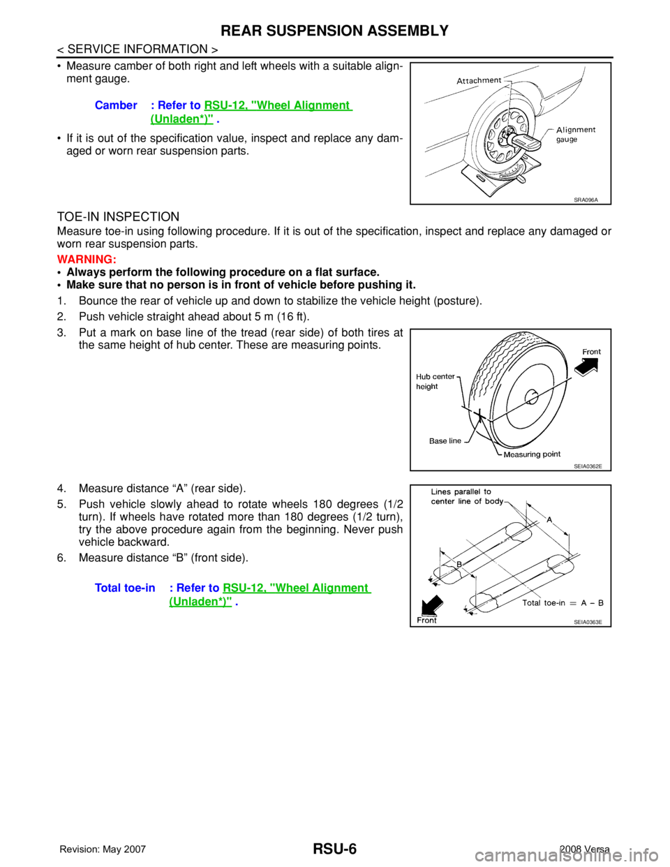
• Measure camber of both right and left wheels with a suitable align-
ment gauge.
• If it is out of the specification value, inspect and replace any dam-
aged or worn rear suspension parts.
TOE-IN INSPECTION
Measure toe-in using following procedure. If it is out of the specification, inspect and replace any damaged or
worn rear suspension parts.
WARNING:
• Always perform the following procedure on a flat surface.
• Make sure that no person is in front of vehicle before pushing it.
1. Bounce the rear of vehicle up and down to stabilize the vehicle height (posture).
2. Push vehicle straight ahead about 5 m (16 ft).
3. Put a mark on base line of the tread (rear side) of both tires at
the same height of hub center. These are measuring points.
4. Measure distance “A” (rear side).
5. Push vehicle slowly ahead to rotate wheels 180 degrees (1/2
turn). If wheels have rotated more than 180 degrees (1/2 turn),
try the above procedure again from the beginning. Never push
vehicle backward.
6. Measure distance “B” (front side).Camber : Refer to RSU-12, "
Wheel Alignment
(Unladen*)" .
SRA096A
SEIA0362E
Total toe-in : Refer to RSU-12, "Wheel Alignment
(Unladen*)" .
SEIA0363E
Page 2571 of 2771
RSU-12
< SERVICE INFORMATION >
SERVICE DATA AND SPECIFICATIONS (SDS)
SERVICE DATA AND SPECIFICATIONS (SDS)
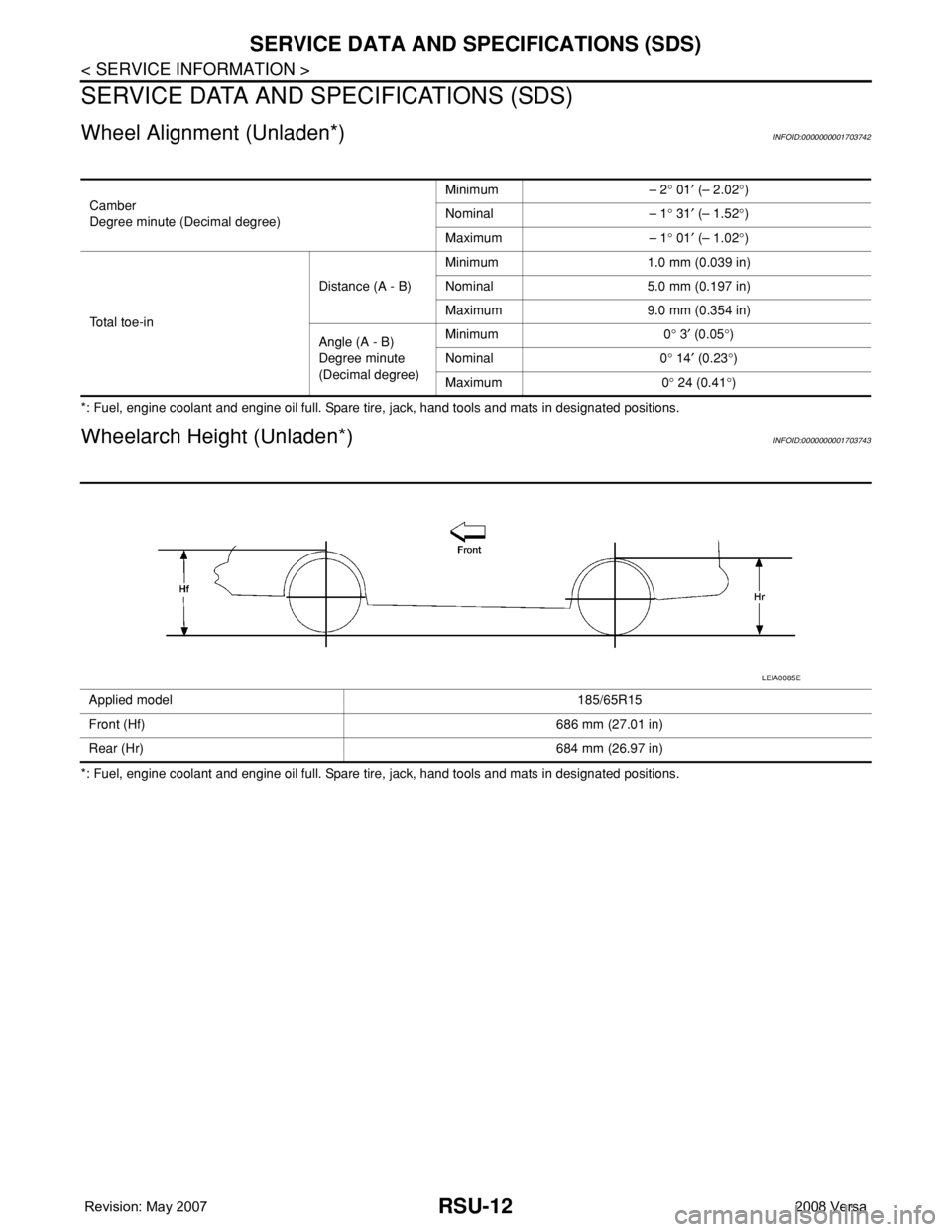
Wheel Alignment (Unladen*)INFOID:0000000001703742
*: Fuel, engine coolant and engine oil full. Spare tire, jack, hand tools and mats in designated positions.
Wheelarch Height (Unladen*)INFOID:0000000001703743
*: Fuel, engine coolant and engine oil full. Spare tire, jack, hand tools and mats in designated positions.Camber
Degree minute (Decimal degree)Minimum – 2° 01′ (– 2.02°)
Nominal – 1° 31′ (– 1.52°)
Maximum – 1° 01′ (– 1.02°)
Total toe-inDistance (A - B)Minimum 1.0 mm (0.039 in)
Nominal 5.0 mm (0.197 in)
Maximum 9.0 mm (0.354 in)
Angle (A - B)
Degree minute
(Decimal degree)Minimum 0° 3′ (0.05°)
Nominal 0° 14′ (0.23°)
Maximum 0° 24 (0.41°)
Applied model 185/65R15
Front (Hf) 686 mm (27.01 in)
Rear (Hr) 684 mm (26.97 in)
LEIA0085E
Page 2579 of 2771
SB-8
< ON-VEHICLE REPAIR >
SEAT BELTS
• The seat belt was damaged in an accident. (i.e. torn webbing, bent retractor or guide, etc.)
• The seat belt attaching point was damaged in an accident. Inspect the seat belt attaching area for damage
or distortion and repair as necessary before installing a new seat belt assembly.
• Anchor bolts are deformed or worn out.
• The seat belt pre-tensioner should be replaced even if the seat belts are not in use during a frontal collision
in which the air bags are deployed.
PRELIMINARY CHECKS
1. Check the seat belt warning lamp/chime for proper operation as follows:
a. Switch ignition ON. The seat belt warning lamp should illuminate. Also, the seat belt warning chime should
sound for about seven seconds.
b. Fasten driver's seat belt. The seat belt warning lamp should go out and the chime (if sounding) should
stop.
2. If the air bag warning lamp is blinking, conduct self-diagnosis using CONSULT-II, and air bag warning
lamp. Refer to SRS-18, "
SRS Operation Check".
3. Check that the seat belt retractor, seat belt anchor and buckle bolts are securely attached.
4. Check the shoulder seat belt guide and shoulder belt height adjuster for front seats. Make sure guide
swivels freely and that webbing lays flat and does not bind in guide. Make sure height adjuster operates
properly and holds securely.
5. Check retractor operation:
a. Fully extend the seat belt webbing and check for twists, tears or other damage.
b. Allow the seat belt to retract. Make sure that webbing returns smoothly and completely into the retractor. If
the seat belt does not return smoothly, wipe the inside of the loops with a clean paper cloth. Dirt build-up
in the loops of the upper anchors can cause the seat belts to retract slowly.
c. Fasten the seat belt. Check the seat belt returns smoothly and completely to the retractor. If the webbing
does not return smoothly, the cause may be an accumulation of dust or dirt. Use the “SEAT BELT TAPE
SET” and perform the following steps.
Inspect the front seat belt though-anchor 1. Pull the seat belt out to a length of 500 mm (19.69 in) or more.
2. Use a clip or other device to attach the seat belt at the center pillar webbing opening.
3. Pass a thin wire though the D-ring anchor webbing opening. Hold both ends of the wire and pull taut
while moving it up and down several times along the webbing opening surface to remove matter stuck
there.
4. Any dirt that cannot be removed with the wire can be removed by cleaning the opening with a clean
cloth.
5. Apply tape at the point where the webbing contacts the though-anchor webbing opening.
NOTE:
Apply the tape so that there is no looseness or wrinkling.
6. Remove the clip attaching the seat belt and check that the webbing returns smoothly.
6. Repeat steps above as necessary to check the other seat belts.
SEAT BELT RETRACTOR ON-VEHICLE CHECK
Emergency Locking Retractors (ELR) and Automatic Locking Retractors (ALR)
NOTE:
All seat belt retractors are of the Emergency Locking Retractors (ELR) type. In an emergency (sudden stop)
the retractor will lock and prevent the webbing from extending any further. All 3-point type seat belt retractors
except the driver's seat belt also have an Automatic Locking Retractors (ALR) mode. The ALR mode (also
called child restraint mode) is used when installing child seats. The ALR mode is activated when the seat belt
is fully extended. When the webbing is then retracted partially, the ALR mode automatically locks the seat belt
in a specific position so the webbing cannot be extended any further. To cancel the ALR mode, allow the seat
belt to fully wind back into the retractor.
Check the seat belt retractors using the following test(s) to determine if a retractor assembly is operating prop-
erly.
ELR Function Stationary Check
Grasp the shoulder webbing and pull it forward quickly. The retractor should lock and prevent the belt from
extending further.