oil pressure NISSAN TIIDA 2008 Service Owner's Guide
[x] Cancel search | Manufacturer: NISSAN, Model Year: 2008, Model line: TIIDA, Model: NISSAN TIIDA 2008Pages: 2771, PDF Size: 60.61 MB
Page 814 of 2771
CLUTCH DISC, CLUTCH COVER AND FLYWHEEL
CL-13
< SERVICE INFORMATION >
D
E
F
G
H
I
J
K
L
MA
B
CL
N
O
P
CLUTCH DISC, CLUTCH COVER AND FLYWHEEL
Removal and InstallationINFOID:0000000001703123
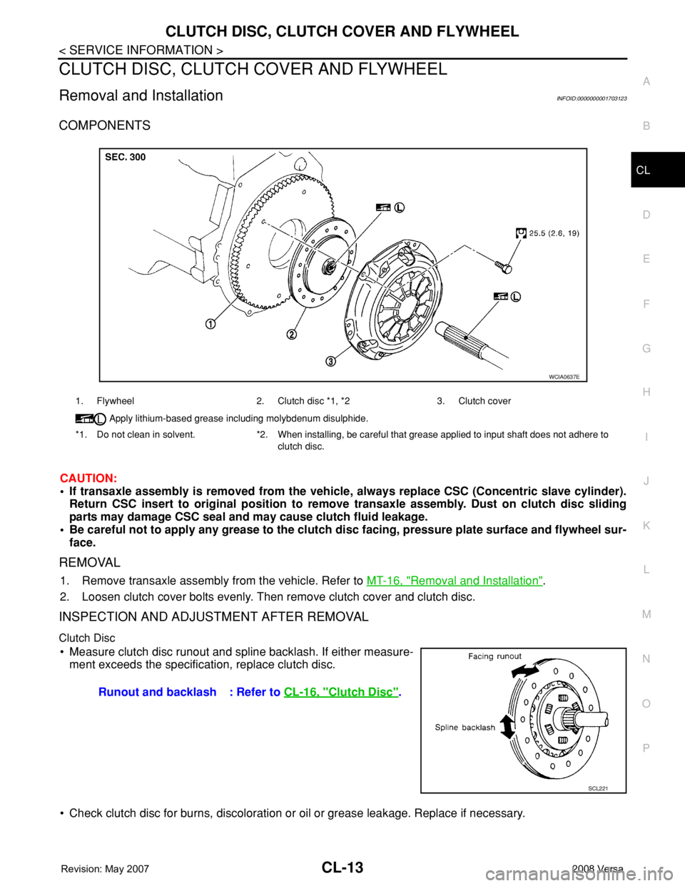
COMPONENTS
CAUTION:
• If transaxle assembly is removed from the vehicle, always replace CSC (Concentric slave cylinder).
Return CSC insert to original position to remove transaxle assembly. Dust on clutch disc sliding
parts may damage CSC seal and may cause clutch fluid leakage.
• Be careful not to apply any grease to the clutch disc facing, pressure plate surface and flywheel sur-
face.
REMOVAL
1. Remove transaxle assembly from the vehicle. Refer to MT-16, "Removal and Installation".
2. Loosen clutch cover bolts evenly. Then remove clutch cover and clutch disc.
INSPECTION AND ADJUSTMENT AFTER REMOVAL
Clutch Disc
• Measure clutch disc runout and spline backlash. If either measure-
ment exceeds the specification, replace clutch disc.
• Check clutch disc for burns, discoloration or oil or grease leakage. Replace if necessary.
1. Flywheel 2. Clutch disc *1, *2 3. Clutch cover
Apply lithium-based grease including molybdenum disulphide.
*1. Do not clean in solvent. *2. When installing, be careful that grease applied to input shaft does not adhere to
clutch disc.
WCIA0637E
Runout and backlash : Refer to CL-16, "Clutch Disc".
SCL221
Page 830 of 2771
RADIATOR
CO-13
< SERVICE INFORMATION >
C
D
E
F
G
H
I
J
K
L
MA
CO
N
P O
Checking Radiator CapINFOID:0000000001702533
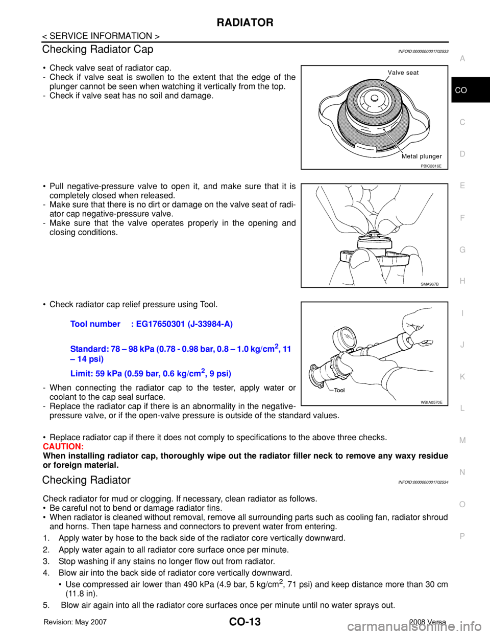
• Check valve seat of radiator cap.
- Check if valve seat is swollen to the extent that the edge of the
plunger cannot be seen when watching it vertically from the top.
- Check if valve seat has no soil and damage.
• Pull negative-pressure valve to open it, and make sure that it is
completely closed when released.
- Make sure that there is no dirt or damage on the valve seat of radi-
ator cap negative-pressure valve.
- Make sure that the valve operates properly in the opening and
closing conditions.
• Check radiator cap relief pressure using Tool.
- When connecting the radiator cap to the tester, apply water or
coolant to the cap seal surface.
- Replace the radiator cap if there is an abnormality in the negative-
pressure valve, or if the open-valve pressure is outside of the standard values.
• Replace radiator cap if there it does not comply to specifications to the above three checks.
CAUTION:
When installing radiator cap, thoroughly wipe out the radiator filler neck to remove any waxy residue
or foreign material.
Checking RadiatorINFOID:0000000001702534
Check radiator for mud or clogging. If necessary, clean radiator as follows.
• Be careful not to bend or damage radiator fins.
• When radiator is cleaned without removal, remove all surrounding parts such as cooling fan, radiator shroud
and horns. Then tape harness and connectors to prevent water from entering.
1. Apply water by hose to the back side of the radiator core vertically downward.
2. Apply water again to all radiator core surface once per minute.
3. Stop washing if any stains no longer flow out from radiator.
4. Blow air into the back side of radiator core vertically downward.
• Use compressed air lower than 490 kPa (4.9 bar, 5 kg/cm
2, 71 psi) and keep distance more than 30 cm
(11.8 in).
5. Blow air again into all the radiator core surfaces once per minute until no water sprays out.
PBIC2816E
SMA967B
Tool number : EG17650301 (J-33984-A)
Standard: 78 – 98 kPa (0.78 - 0.98 bar, 0.8 – 1.0 kg/cm
2, 11
– 14 psi)
Limit: 59 kPa (0.59 bar, 0.6 kg/cm
2, 9 psi)
WBIA0570E
Page 843 of 2771

CVT-4
DTC P1740 LOCK-UP SELECT SOLENOID
VALVE CIRCUIT ..............................................
132
Description .............................................................132
CONSULT-III Reference Value in Data Monitor
Mode ......................................................................
132
On Board Diagnosis Logic .....................................132
Possible Cause ......................................................132
DTC Confirmation Procedure ................................132
Wiring Diagram - CVT - L/USSV ............................133
Diagnosis Procedure .............................................134
Component Inspection ...........................................135
DTC P1745 LINE PRESSURE CONTROL ......136
Description .............................................................136
On Board Diagnosis Logic .....................................136
Possible Cause ......................................................136
DTC Confirmation Procedure ................................136
Diagnosis Procedure .............................................136
DTC P1777 STEP MOTOR - CIRCUIT ............137
Description .............................................................137
CONSULT-III Reference Value in Data Monitor
Mode ......................................................................
137
On Board Diagnosis Logic .....................................137
Possible Cause ......................................................137
DTC Confirmation Procedure ................................137
Wiring Diagram - CVT - STM .................................138
Diagnosis Procedure .............................................139
Component Inspection ...........................................140
DTC P1778 STEP MOTOR - FUNCTION ........141
Description .............................................................141
CONSULT-III Reference Value in Data Monitor
Mode ......................................................................
141
On Board Diagnosis Logic .....................................141
Possible Cause ......................................................141
DTC Confirmation Procedure ................................141
Diagnosis Procedure .............................................142
OVERDRIVE CONTROL SWITCH ..................143
Description .............................................................143
CONSULT-III Reference Value in Data Monitor
Mode ......................................................................
143
Wiring Diagram - CVT - ODSW .............................144
Diagnosis Procedure .............................................144
Component Inspection ...........................................146
SHIFT POSITION INDICATOR CIRCUIT ........148
Description .............................................................148
CONSULT-III Reference Value in Data Monitor
Mode ......................................................................
148
Diagnosis Procedure .............................................148
TROUBLE DIAGNOSIS FOR SYMPTOMS .....149
Wiring Diagram - CVT - NONDTC .........................149
O/D OFF Indicator Lamp Does Not Come On ......151
Engine Cannot Be Started in "P" and "N" Position .153
In "P" Position, Vehicle Moves Forward or Back-
ward When Pushed ...............................................
153
In "N" Position, Vehicle Moves ..............................154
Large Shock "N" → "R" Position ...........................154
Vehicle Does Not Creep Backward in "R" Position .155
Vehicle Does Not Creep Forward in "D" or "L" Po-
sition ......................................................................
156
Vehicle Speed Does Not Change in "L" Position ..157
Vehicle Speed Does Not Change in overdrive-off
mode .....................................................................
158
Vehicle Speed Does Not Change in "D" Position .159
Vehicle Does Not Decelerate by Engine Brake ....159
TRANSMISSION CONTROL MODULE ...........161
Removal and Installation .......................................161
CVT SHIFT LOCK SYSTEM .............................162
Description ............................................................162
Shift Lock System Electrical Parts Location ..........162
Wiring Diagram - CVT - SHIFT .............................163
Diagnosis Procedure .............................................163
SHIFT CONTROL SYSTEM .............................167
Removal and Installation .......................................167
Control Device Disassembly and Assembly .........170
Selector Lever Knob Removal and Installation .....170
Adjustment of CVT Position ..................................171
Checking of CVT Position .....................................171
KEY INTERLOCK CABLE ...............................173
Removal and Installation .......................................173
AIR BREATHER HOSE ....................................176
Removal and Installation .......................................176
DIFFERENTIAL SIDE OIL SEAL .....................177
Removal and Installation .......................................177
TRANSAXLE ASSEMBLY ...............................178
Removal and Installation .......................................178
SERVICE DATA AND SPECIFICATIONS
(SDS) ................................................................
181
General Specification ............................................181
Vehicle Speed When Shifting Gears .....................181
Stall Speed ............................................................181
Line Pressure ........................................................181
Solenoid Valves ....................................................182
CVT Fluid Temperature Sensor ............................182
Primary Speed Sensor ..........................................182
Secondary Speed Sensor .....................................182
Removal and Installation .......................................182
Page 851 of 2771
CVT-12
< SERVICE INFORMATION >
PREPARATION
PREPARATION
Special Service ToolINFOID:0000000001703431
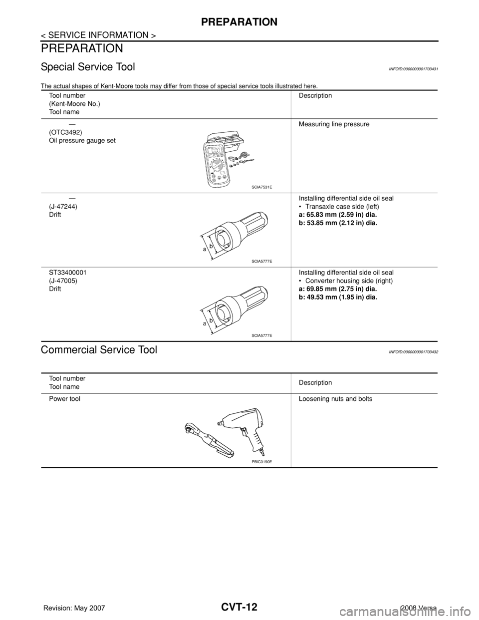
The actual shapes of Kent-Moore tools may differ from those of special service tools illustrated here.
Commercial Service ToolINFOID:0000000001703432
Tool number
(Kent-Moore No.)
Tool nameDescription
—
(OTC3492)
Oil pressure gauge setMeasuring line pressure
—
(J-47244)
DriftInstalling differential side oil seal
• Transaxle case side (left)
a: 65.83 mm (2.59 in) dia.
b: 53.85 mm (2.12 in) dia.
ST33400001
(J-47005)
DriftInstalling differential side oil seal
• Converter housing side (right)
a: 69.85 mm (2.75 in) dia.
b: 49.53 mm (1.95 in) dia.
SCIA7531E
SCIA5777E
SCIA5777E
Tool number
Tool nameDescription
Power toolLoosening nuts and bolts
PBIC0190E
Page 861 of 2771
CVT-22
< SERVICE INFORMATION >
CVT SYSTEM
Input/Output Signal of TCM
INFOID:0000000001703441
*1: Input by CAN communications.
*2: Output by CAN communications.
*3: If these input and output signals are different, the TCM triggers the fail-safe function.
Line Pressure and Secondary Pressure ControlINFOID:0000000001703442
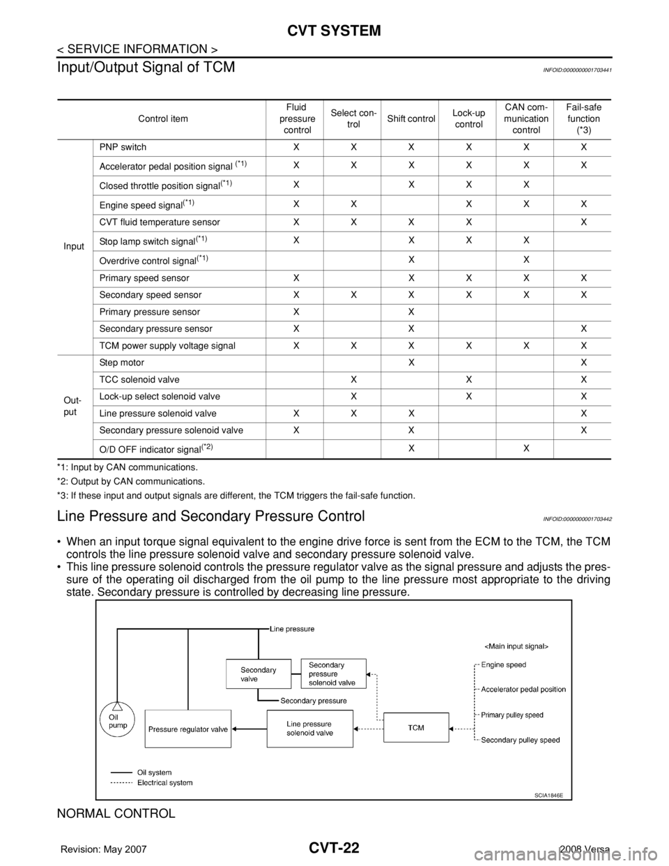
• When an input torque signal equivalent to the engine drive force is sent from the ECM to the TCM, the TCM
controls the line pressure solenoid valve and secondary pressure solenoid valve.
• This line pressure solenoid controls the pressure regulator valve as the signal pressure and adjusts the pres-
sure of the operating oil discharged from the oil pump to the line pressure most appropriate to the driving
state. Secondary pressure is controlled by decreasing line pressure.
NORMAL CONTROL
Control itemFluid
pressure
controlSelect con-
trolShift controlLock-up
controlCAN com-
munication
controlFail-safe
function
(*3)
InputPNP switch XXXXXX
Accelerator pedal position signal
(*1)XXXXXX
Closed throttle position signal
(*1)X XXX
Engine speed signal
(*1)XX XXX
CVT fluid temperature sensor X X X X X
Stop lamp switch signal
(*1)X XXX
Overdrive control signal
(*1)XX
Primary speed sensor X X X X X
Secondary speed sensor X X X X X X
Primary pressure sensor X X
Secondary pressure sensor X X X
TCM power supply voltage signal X X X X X X
Out-
putStep motor X X
TCC solenoid valve X X X
Lock-up select solenoid valve X X X
Line pressure solenoid valve X X X X
Secondary pressure solenoid valve X X X
O/D OFF indicator signal
(*2)XX
SCIA1846E
Page 864 of 2771
CVT SYSTEM
CVT-25
< SERVICE INFORMATION >
D
E
F
G
H
I
J
K
L
MA
B
CVT
N
O
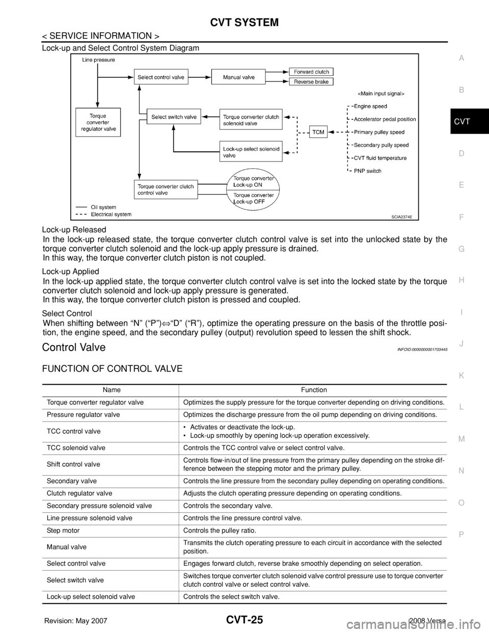
P Lock-up and Select Control System Diagram
Lock-up Released
In the lock-up released state, the torque converter clutch control valve is set into the unlocked state by the
torque converter clutch solenoid and the lock-up apply pressure is drained.
In this way, the torque converter clutch piston is not coupled.
Lock-up Applied
In the lock-up applied state, the torque converter clutch control valve is set into the locked state by the torque
converter clutch solenoid and lock-up apply pressure is generated.
In this way, the torque converter clutch piston is pressed and coupled.
Select Control
When shifting between “N” (“P”)⇔“D” (“R”), optimize the operating pressure on the basis of the throttle posi-
tion, the engine speed, and the secondary pulley (output) revolution speed to lessen the shift shock.
Control ValveINFOID:0000000001703445
FUNCTION OF CONTROL VALVE
SCIA2374E
Name Function
Torque converter regulator valve Optimizes the supply pressure for the torque converter depending on driving conditions.
Pressure regulator valve Optimizes the discharge pressure from the oil pump depending on driving conditions.
TCC control valve• Activates or deactivate the lock-up.
• Lock-up smoothly by opening lock-up operation excessively.
TCC solenoid valve Controls the TCC control valve or select control valve.
Shift control valveControls flow-in/out of line pressure from the primary pulley depending on the stroke dif-
ference between the stepping motor and the primary pulley.
Secondary valve Controls the line pressure from the secondary pulley depending on operating conditions.
Clutch regulator valve Adjusts the clutch operating pressure depending on operating conditions.
Secondary pressure solenoid valve Controls the secondary valve.
Line pressure solenoid valve Controls the line pressure control valve.
Step motor Controls the pulley ratio.
Manual valveTransmits the clutch operating pressure to each circuit in accordance with the selected
position.
Select control valve Engages forward clutch, reverse brake smoothly depending on select operation.
Select switch valveSwitches torque converter clutch solenoid valve control pressure use to torque converter
clutch control valve or select control valve.
Lock-up select solenoid valve Controls the select switch valve.
Page 868 of 2771

TROUBLE DIAGNOSIS
CVT-29
< SERVICE INFORMATION >
D
E
F
G
H
I
J
K
L
MA
B
CVT
N
O
P
TROUBLE DIAGNOSIS
DTC Inspection Priority ChartINFOID:0000000001703451
If some DTCs are displayed at the same time, perform inspections one by one based on the following priority
chart.
NOTE:
If DTC “U1000 CAN COMM CIRCUIT” is displayed with other DTCs, first perform the trouble diagnosis
for “DTC U1000 CAN COMMUNICATION LINE”. Refer to CVT-56
.
Fail-SafeINFOID:0000000001703452
The TCM has an electrical fail-safe mode. This mode makes it possible to operate even if there is an error in a
main electronic control input/output signal circuit.
FAIL-SAFE FUNCTION
If any malfunction occurs in a sensor or solenoid, this function controls the CVT to make driving possible.
Output Speed Sensor (Secondary Speed Sensor)
The shift pattern is changed in accordance with throttle position when an unexpected signal is sent from the
output speed sensor (secondary speed sensor) to the TCM. The overdrive-off mode is inhibited, and the tran-
saxle is put in “D”.
Input Speed Sensor (Primary Speed Sensor)
The shift pattern is changed in accordance with throttle position and secondary speed (vehicle speed) when
an unexpected signal is sent from the input speed sensor (primary speed sensor) to the TCM. The sport mode
is inhibited, and the transaxle is put in “D”.
PNP Switch
If an unexpected signal is sent from the PNP switch to the TCM, the transaxle is put in “D”.
CVT Fluid Temperature Sensor
If an unexpected signal is sent from the CVT fluid temperature sensor to the TCM, the gear ratio in use before
receiving the unexpected signal is maintained or the gear ratio is controlled to keep engine speed under 3500
rpm.
Transmission Fluid Pressure Sensor A (Secondary Pressure Sensor)
• If an unexpected signal is sent from the transmission fluid pressure sensor A (secondary pressure sensor) to
the TCM, the secondary pressure feedback control is stopped and the offset value obtained before the non-
standard condition occurs is used to control line pressure.
• If transmission fluid pressure sensor A (secondary pressure sensor) error signal is input to TCM, secondary
pressure feedback control stops, but line pressure is controlled normally.
Pressure Control Solenoid A (Line Pressure Solenoid)
If an unexpected signal is sent from the solenoid to the TCM, the pressure control solenoid A (line pressure
solenoid) is turned OFF to achieve the maximum fluid pressure.
Pressure Control Solenoid B (Secondary Pressure Solenoid)
If an unexpected signal is sent from the solenoid to the TCM, the pressure control solenoid B (secondary pres-
sure solenoid) is turned OFF to achieve the maximum fluid pressure.
Torque Converter Clutch Solenoid
If an unexpected signal is sent from the solenoid to the TCM, the torque converter clutch solenoid is turned
OFF to cancel the lock-up.
Ste p M oto r
If an unexpected signal is sent from the step motor to the TCM, the step motor coil phases “A” through “D” are
all turned OFF to hold the gear ratio used right before the non-standard condition occurred.
CVT Lock-up Select Solenoid
Priority Detected items (DTC)
1 U1000 CAN communication line
2 Except above
Page 877 of 2771
CVT-38
< SERVICE INFORMATION >
TROUBLE DIAGNOSIS
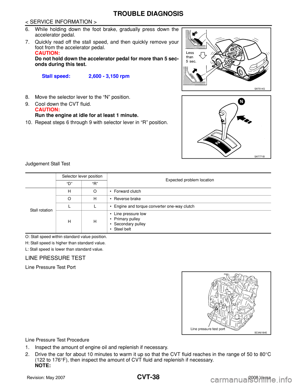
6. While holding down the foot brake, gradually press down the
accelerator pedal.
7. Quickly read off the stall speed, and then quickly remove your
foot from the accelerator pedal.
CAUTION:
Do not hold down the accelerator pedal for more than 5 sec-
onds during this test.
8. Move the selector lever to the “N” position.
9. Cool down the CVT fluid.
CAUTION:
Run the engine at idle for at least 1 minute.
10. Repeat steps 6 through 9 with selector lever in “R” position.
Judgement Stall Test
O: Stall speed within standard value position.
H: Stall speed is higher than standard value.
L: Stall speed is lower than standard value.
LINE PRESSURE TEST
Line Pressure Test Port
Line Pressure Test Procedure
1. Inspect the amount of engine oil and replenish if necessary.
2. Drive the car for about 10 minutes to warm it up so that the CVT fluid reaches in the range of 50 to 80°C
(122 to 176°F), then inspect the amount of CVT fluid and replenish if necessary.
NOTE:Stall speed: 2,600 - 3,150 rpm
SAT514G
SAT771B
Selector lever position
Expected problem location
“D” “R”
Stall rotation HO•Forward clutch
O H • Reverse brake
L L • Engine and torque converter one-way clutch
HH• Line pressure low
• Primary pulley
• Secondary pulley
• Steel belt
SCIA6184E
Page 878 of 2771
TROUBLE DIAGNOSIS
CVT-39
< SERVICE INFORMATION >
D
E
F
G
H
I
J
K
L
MA
B
CVT
N
O
P
The CVT fluid temperature rises in the range of 50 - 80°C (122 - 176°F) during 10 minutes of driving.
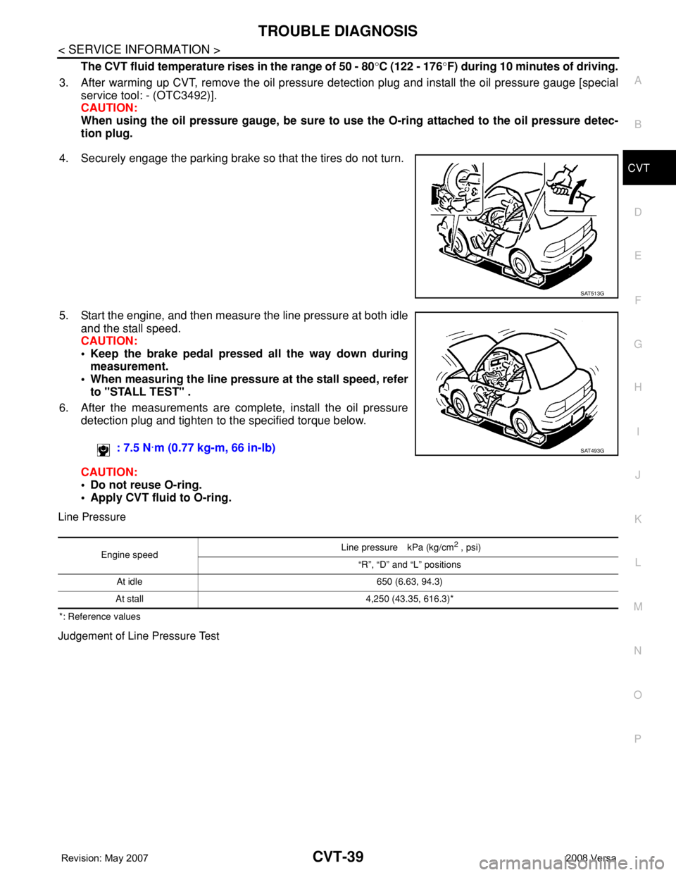
3. After warming up CVT, remove the oil pressure detection plug and install the oil pressure gauge [special
service tool: - (OTC3492)].
CAUTION:
When using the oil pressure gauge, be sure to use the O-ring attached to the oil pressure detec-
tion plug.
4. Securely engage the parking brake so that the tires do not turn.
5. Start the engine, and then measure the line pressure at both idle
and the stall speed.
CAUTION:
• Keep the brake pedal pressed all the way down during
measurement.
• When measuring the line pressure at the stall speed, refer
to "STALL TEST" .
6. After the measurements are complete, install the oil pressure
detection plug and tighten to the specified torque below.
CAUTION:
• Do not reuse O-ring.
• Apply CVT fluid to O-ring.
Line Pressure
*: Reference values
Judgement of Line Pressure Test
SAT513G
: 7.5 N·m (0.77 kg-m, 66 in-lb)SAT493G
Engine speed Line pressure kPa (kg/cm
2 , psi)
“R”, “D” and “L” positions
At idle 650 (6.63, 94.3)
At stall 4,250 (43.35, 616.3)*
Page 879 of 2771
CVT-40
< SERVICE INFORMATION >
TROUBLE DIAGNOSIS
Road Test
INFOID:0000000001703457
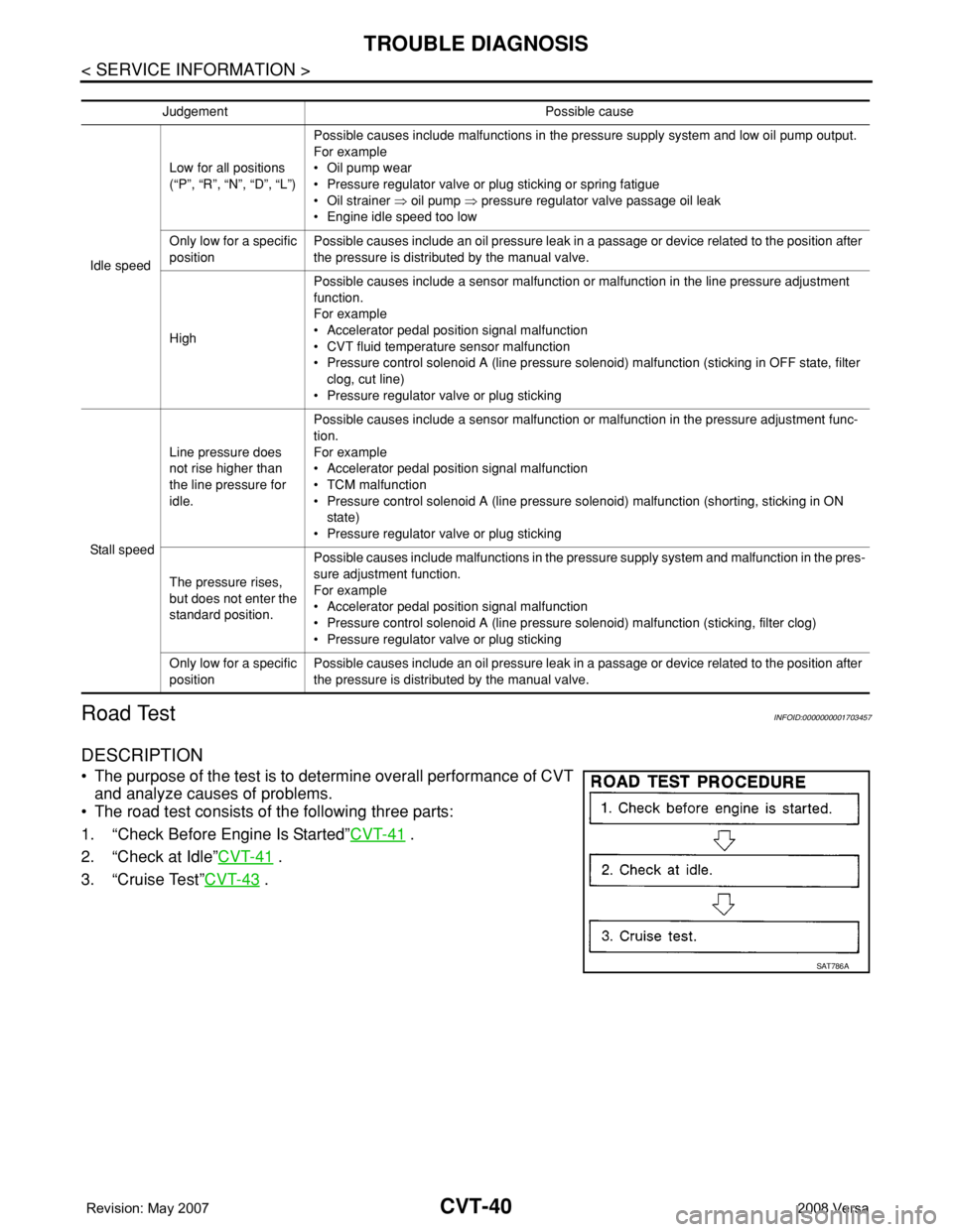
DESCRIPTION
• The purpose of the test is to determine overall performance of CVT
and analyze causes of problems.
• The road test consists of the following three parts:
1. “Check Before Engine Is Started”CVT-41
.
2. “Check at Idle”CVT-41
.
3. “Cruise Test”CVT-43
.
Judgement Possible cause
Idle speedLow for all positions
(“P”, “R”, “N”, “D”, “L”)Possible causes include malfunctions in the pressure supply system and low oil pump output.
For example
•Oil pump wear
• Pressure regulator valve or plug sticking or spring fatigue
•Oil strainer ⇒ oil pump ⇒ pressure regulator valve passage oil leak
• Engine idle speed too low
Only low for a specific
positionPossible causes include an oil pressure leak in a passage or device related to the position after
the pressure is distributed by the manual valve.
HighPossible causes include a sensor malfunction or malfunction in the line pressure adjustment
function.
For example
• Accelerator pedal position signal malfunction
• CVT fluid temperature sensor malfunction
• Pressure control solenoid A (line pressure solenoid) malfunction (sticking in OFF state, filter
clog, cut line)
• Pressure regulator valve or plug sticking
Sta ll sp ee dLine pressure does
not rise higher than
the line pressure for
idle.Possible causes include a sensor malfunction or malfunction in the pressure adjustment func-
tion.
For example
• Accelerator pedal position signal malfunction
•TCM malfunction
• Pressure control solenoid A (line pressure solenoid) malfunction (shorting, sticking in ON
state)
• Pressure regulator valve or plug sticking
The pressure rises,
but does not enter the
standard position.Possible causes include malfunctions in the pressure supply system and malfunction in the pres-
sure adjustment function.
For example
• Accelerator pedal position signal malfunction
• Pressure control solenoid A (line pressure solenoid) malfunction (sticking, filter clog)
• Pressure regulator valve or plug sticking
Only low for a specific
positionPossible causes include an oil pressure leak in a passage or device related to the position after
the pressure is distributed by the manual valve.
SAT786A