EI- NISSAN TIIDA 2008 Service Service Manual
[x] Cancel search | Manufacturer: NISSAN, Model Year: 2008, Model line: TIIDA, Model: NISSAN TIIDA 2008Pages: 2771, PDF Size: 60.61 MB
Page 1643 of 2771
EI-20
< ON-VEHICLE REPAIR >
FRONT GRILLE
FRONT GRILLE
Removal and InstallationINFOID:0000000001704222
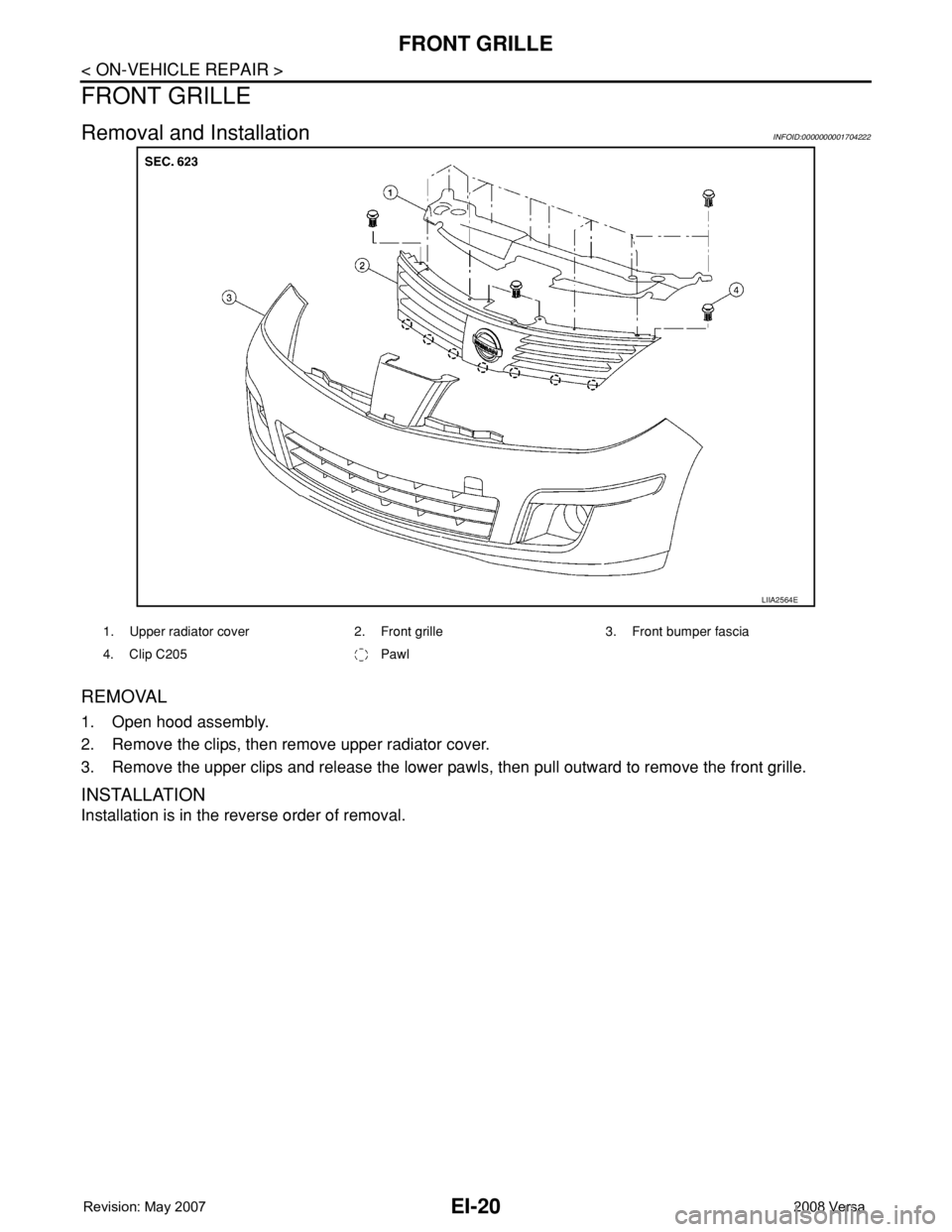
REMOVAL
1. Open hood assembly.
2. Remove the clips, then remove upper radiator cover.
3. Remove the upper clips and release the lower pawls, then pull outward to remove the front grille.
INSTALLATION
Installation is in the reverse order of removal.
LIIA2564E
1. Upper radiator cover 2. Front grille 3. Front bumper fascia
4. Clip C205 Pawl
Page 1644 of 2771

COWL TOP
EI-21
< ON-VEHICLE REPAIR >
C
D
E
F
G
H
J
K
L
MA
B
EI
N
O
P
COWL TOP
Removal and InstallationINFOID:0000000001704223
REMOVAL
1. Remove front wiper arm RH/LH from vehicle. Refer to WW-18, "Removal and Installation of Front Wiper
Arms".
2. Disconnect washer tube.
3. Remove fender seal and fender cover RH/LH.
4. Release the cowl top seal clips, then remove cowl top seal.
LIIA2565E
1. Fender cover 2. Fender seal 3. Washer tube
4. Cowl top seal 5. Cowl extension panel 6. Dual lock fastener
7. Double-faced adhesive tape 8. Cowl top cover 9. Clip C205
10. EPT sealer 11. Cowl extension clip 12. Cover
Clip CE103⇐Vehicle front
PIIB2555J
Page 1645 of 2771

EI-22
< ON-VEHICLE REPAIR >
COWL TOP
5. Release the cowl extension clip (1) by prying the center pawls
apart and pulling clip outward. Remove remaining clips, then
remove cowl top cover (2).
6. Disconnect and remove the front wiper motor and linkage
assembly. Refer to WW-19, "
Removal and Installation of Front
Wiper Drive Assembly".
CAUTION:
To avoid damage, make sure to cover the lower edge of
windshield with suitable protection material.
7. Remove cowl extension panel bolts, then remove cowl extension panel.
INSTALLATION
Installation is in the reverse order of removal.
NOTE:
• For wiper arm RH/LH installation and adjustment, Refer to WW-18, "
Removal and Installation of Front Wiper
Arms".
• Always replace EPT sealer and double-faced adhesive tape when installing cowl top cover.
LIIA2566E
PIIB6038E
Page 1646 of 2771

FENDER PROTECTOR
EI-23
< ON-VEHICLE REPAIR >
C
D
E
F
G
H
J
K
L
MA
B
EI
N
O
P
FENDER PROTECTOR
ComponentINFOID:0000000001704224
Removal and InstallationINFOID:0000000001704225
FRONT FENDER PROTECTOR
Removal
1. Remove front fender protector bolts and clips.
2. Remove front fender protector.
Installation
Installation is in the reverse order of removal.
REAR FENDER PROTECTOR
Removal
1. Remove rear fender protector bolt and clip.
2. Remove rear fender protector.
Installation
Installation is in the reverse order of removal.
1. Front fender protector 2. Clip C205 3. Rear fender protector
Clip C103⇐Vehicle front
LIIA2567E
Page 1647 of 2771

EI-24
< ON-VEHICLE REPAIR >
ROOF SIDE MOLDING
ROOF SIDE MOLDING
ComponentINFOID:0000000001704226
Hatchback Models
Sedan Models
Removal and InstallationINFOID:0000000001704227
REMOVAL
1. Using a suitable tool, release the rear roof side molding clip and remove.
2. Lift up rear edge of roof side molding working forward.
3. Release front roof side molding clip, then remove roof side molding.
INSTALLATION
Installation is in the reverse order of removal.
NOTE:
WIIA1408E
1. Roof side molding A. Front roof side molding clip B. Rear roof side molding clip
WIIA1409E
1. Roof side molding A. Front roof side molding clip B. Rear roof side molding clip
Page 1648 of 2771

ROOF SIDE MOLDING
EI-25
< ON-VEHICLE REPAIR >
C
D
E
F
G
H
J
K
L
MA
B
EI
N
O
P
Make sure front edge of roof side molding contacts windshield mold-
ing with no gap.
• For setting a new clip A or B, use Epoxy Adhesive DP-100C made
by 3M. For adhesive DP-100C application use an applicator 9170
EPX W 1:1 and mixer nozzle 9742 EPX 50ML made by 3M.
PIIB2599J
Page 1649 of 2771

EI-26
< ON-VEHICLE REPAIR >
DOOR OUTSIDE MOLDING
DOOR OUTSIDE MOLDING
ComponentINFOID:0000000001704228
Hatchback Models
WIIA1410E
1. Front door outside molding 2. Rear door outside molding 3. Rear door corner cover
A. Clip C101
Page 1650 of 2771
DOOR OUTSIDE MOLDING
EI-27
< ON-VEHICLE REPAIR >
C
D
E
F
G
H
J
K
L
MA
B
EI
N
O
P
Sedan Models
Removal and InstallationINFOID:0000000001704229
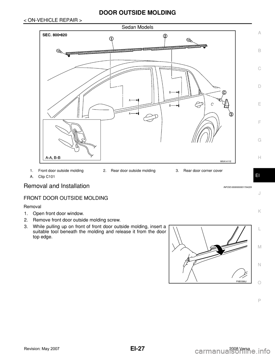
FRONT DOOR OUTSIDE MOLDING
Removal
1. Open front door window.
2. Remove front door outside molding screw.
3. While pulling up on front of front door outside molding, insert a
suitable tool beneath the molding and release it from the door
top edge.
WIIA1411E
1. Front door outside molding 2. Rear door outside molding 3. Rear door corner cover
A. Clip C101
PIIB3386J
Page 1651 of 2771
EI-28
< ON-VEHICLE REPAIR >
DOOR OUTSIDE MOLDING
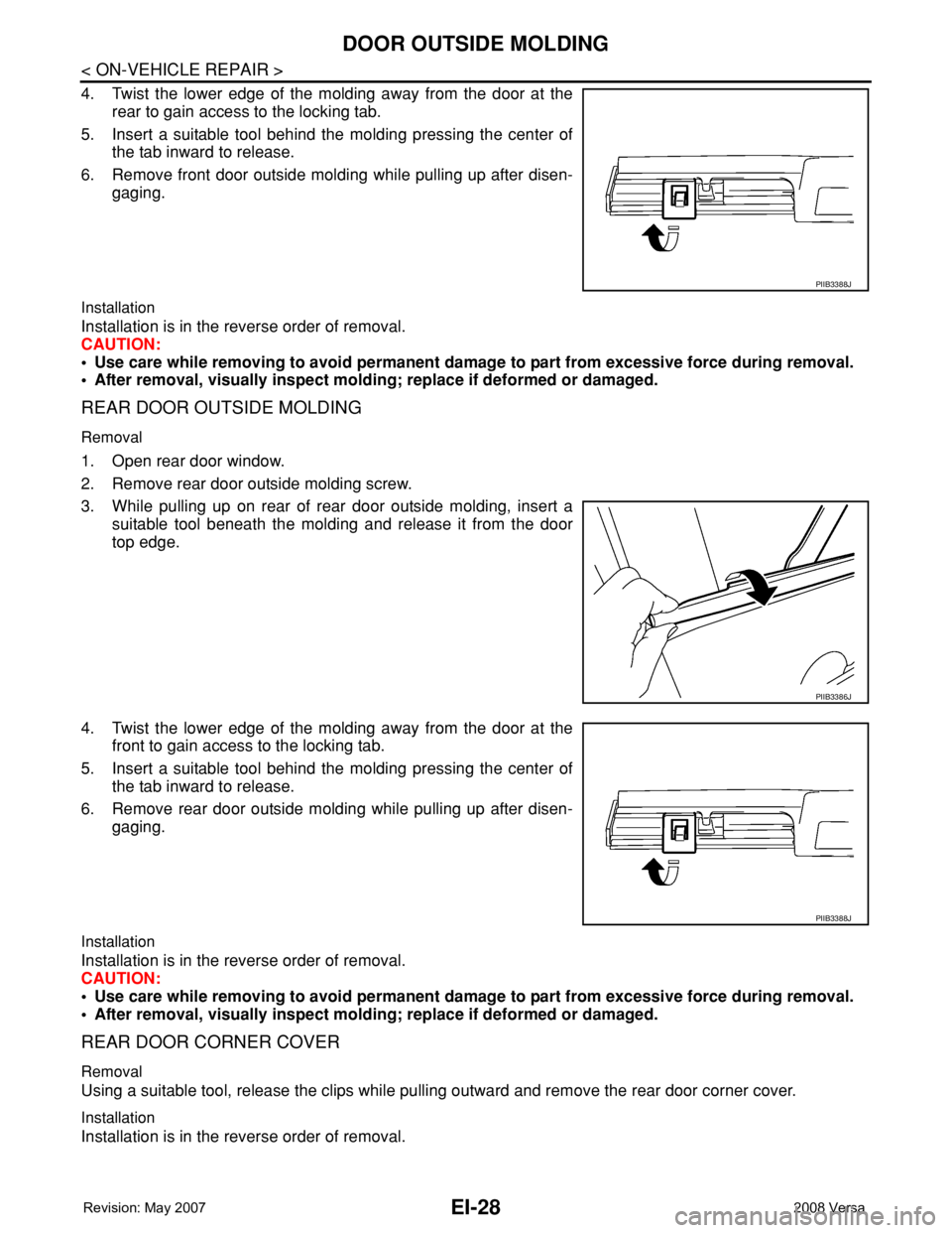
4. Twist the lower edge of the molding away from the door at the
rear to gain access to the locking tab.
5. Insert a suitable tool behind the molding pressing the center of
the tab inward to release.
6. Remove front door outside molding while pulling up after disen-
gaging.
Installation
Installation is in the reverse order of removal.
CAUTION:
• Use care while removing to avoid permanent damage to part from excessive force during removal.
• After removal, visually inspect molding; replace if deformed or damaged.
REAR DOOR OUTSIDE MOLDING
Removal
1. Open rear door window.
2. Remove rear door outside molding screw.
3. While pulling up on rear of rear door outside molding, insert a
suitable tool beneath the molding and release it from the door
top edge.
4. Twist the lower edge of the molding away from the door at the
front to gain access to the locking tab.
5. Insert a suitable tool behind the molding pressing the center of
the tab inward to release.
6. Remove rear door outside molding while pulling up after disen-
gaging.
Installation
Installation is in the reverse order of removal.
CAUTION:
• Use care while removing to avoid permanent damage to part from excessive force during removal.
• After removal, visually inspect molding; replace if deformed or damaged.
REAR DOOR CORNER COVER
Removal
Using a suitable tool, release the clips while pulling outward and remove the rear door corner cover.
Installation
Installation is in the reverse order of removal.
PIIB3388J
PIIB3386J
PIIB3388J
Page 1652 of 2771
CENTER MUD GUARD
EI-29
< ON-VEHICLE REPAIR >
C
D
E
F
G
H
J
K
L
MA
B
EI
N
O
P
CENTER MUD GUARD
Removal and InstallationINFOID:0000000001704230
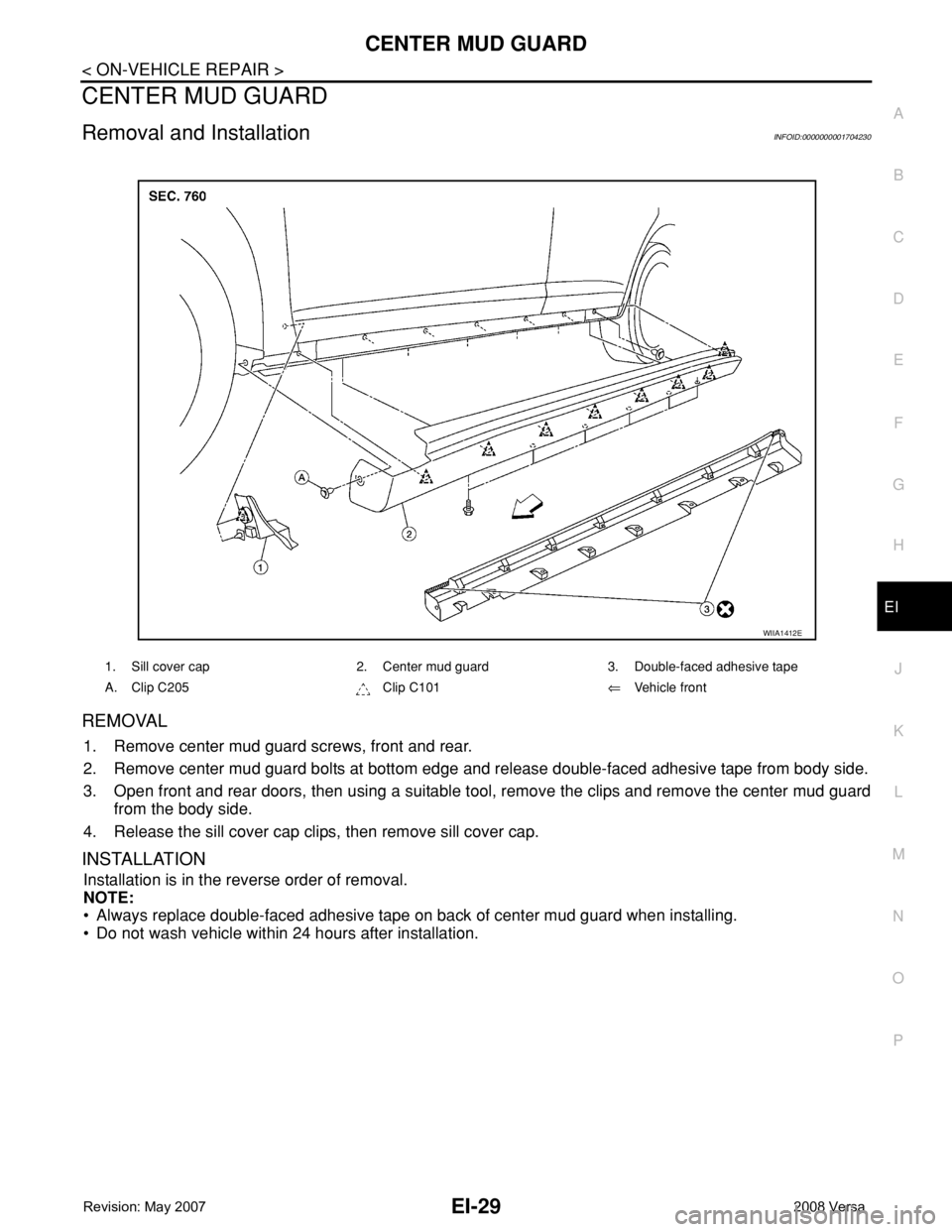
REMOVAL
1. Remove center mud guard screws, front and rear.
2. Remove center mud guard bolts at bottom edge and release double-faced adhesive tape from body side.
3. Open front and rear doors, then using a suitable tool, remove the clips and remove the center mud guard
from the body side.
4. Release the sill cover cap clips, then remove sill cover cap.
INSTALLATION
Installation is in the reverse order of removal.
NOTE:
• Always replace double-faced adhesive tape on back of center mud guard when installing.
• Do not wash vehicle within 24 hours after installation.
1. Sill cover cap 2. Center mud guard 3. Double-faced adhesive tape
A. Clip C205 Clip C101⇐Vehicle front
WIIA1412E