torque NISSAN TIIDA 2008 Service Repair Manual
[x] Cancel search | Manufacturer: NISSAN, Model Year: 2008, Model line: TIIDA, Model: NISSAN TIIDA 2008Pages: 2771, PDF Size: 60.61 MB
Page 14 of 2771

AT-2
DTC Confirmation Procedure .................................86
Wiring Diagram - AT - PNP/SW ..............................87
Diagnosis Procedure ..............................................88
Component Inspection ............................................90
DTC P0710 A/T FLUID TEMPERATURE SEN-
SOR CIRCUIT ....................................................
91
Description ..............................................................91
CONSULT-III Reference Value in Data Monitor
Mode .......................................................................
91
On Board Diagnosis Logic ......................................91
Possible Cause .......................................................91
DTC Confirmation Procedure .................................91
Wiring Diagram - AT - FTS .....................................92
Diagnosis Procedure ..............................................92
Component Inspection ............................................95
DTC P0720 VEHICLE SPEED SENSOR A/T
(REVOLUTION SENSOR) .................................
96
Description ..............................................................96
CONSULT-III Reference Value in Data Monitor
Mode .......................................................................
96
On Board Diagnosis Logic ......................................96
Possible Cause .......................................................96
DTC Confirmation Procedure .................................96
Wiring Diagram - AT - VSSA/T ...............................97
Diagnosis Procedure ..............................................98
DTC P0725 ENGINE SPEED SIGNAL ............101
Description .............................................................101
CONSULT-III Reference Value in Data Monitor
Mode ......................................................................
101
On Board Diagnosis Logic .....................................101
Possible Cause ......................................................101
DTC Confirmation Procedure ................................101
Wiring Diagram - AT - ENGSS ..............................102
Diagnosis Procedure .............................................103
DTC P0731 A/T 1ST GEAR FUNCTION .........105
Description .............................................................105
On Board Diagnosis Logic .....................................105
Possible Cause ......................................................105
DTC Confirmation Procedure ................................105
Diagnosis Procedure .............................................106
DTC P0732 A/T 2ND GEAR FUNCTION .........108
Description .............................................................108
On Board Diagnosis Logic .....................................108
Possible Cause ......................................................108
DTC Confirmation Procedure ................................108
Diagnosis Procedure .............................................109
DTC P0733 A/T 3RD GEAR FUNCTION .........111
Description .............................................................111
On Board Diagnosis Logic .....................................111
Possible Cause ......................................................111
DTC Confirmation Procedure ................................111
Diagnosis Procedure .............................................112
DTC P0734 A/T 4TH GEAR FUNCTION .........114
Description ............................................................114
CONSULT-III Reference Value in Data Monitor
Mode .....................................................................
114
On Board Diagnosis Logic ....................................114
Possible Cause .....................................................114
DTC Confirmation Procedure ................................114
Diagnosis Procedure .............................................115
DTC P0740 TORQUE CONVERTER CLUTCH
SOLENOID VALVE ..........................................
119
Description ............................................................119
CONSULT-III Reference Value in Data Monitor
Mode .....................................................................
119
On Board Diagnosis Logic ....................................119
Possible Cause .....................................................119
DTC Confirmation Procedure ................................119
Wiring Diagram - AT - TCV ...................................120
Diagnosis Procedure .............................................121
Component Inspection ..........................................122
DTC P0744 A/T TCC S/V FUNCTION (LOCK-
UP) ....................................................................
124
Description ............................................................124
CONSULT-III Reference Value in Data Monitor
Mode .....................................................................
124
On Board Diagnosis Logic ....................................124
Possible Cause .....................................................124
DTC Confirmation Procedure ................................124
Diagnosis Procedure .............................................125
DTC P0745 LINE PRESSURE SOLENOID
VALVE ..............................................................
129
Description ............................................................129
CONSULT-III Reference Value in Data Monitor
Mode .....................................................................
129
On Board Diagnosis Logic ....................................129
Possible Cause .....................................................129
DTC Confirmation Procedure ................................129
Wiring Diagram - AT - LPSV .................................130
Diagnosis Procedure .............................................131
Component Inspection ..........................................133
DTC P0750 SHIFT SOLENOID VALVE A ........134
Description ............................................................134
CONSULT-III Reference Value in Data Monitor
Mode .....................................................................
134
On Board Diagnosis Logic ....................................134
Possible Cause .....................................................134
DTC Confirmation Procedure ................................134
Wiring Diagram - AT - SSV/A ................................135
Diagnosis Procedure .............................................136
Component Inspection ..........................................137
DTC P0755 SHIFT SOLENOID VALVE B ........139
Description ............................................................139
CONSULT-III Reference Value in Data Monitor
Mode .....................................................................
139
On Board Diagnosis Logic ....................................139
Possible Cause .....................................................139
DTC Confirmation Procedure ................................139
Page 21 of 2771
PRECAUTIONS
AT-9
< SERVICE INFORMATION >
D
E
F
G
H
I
J
K
L
MA
B
AT
N
O
P
• Before assembly, apply a coat of recommended ATF to all parts. Apply petroleum jelly to protect O-rings and
seals, or hold bearings and washers in place during assembly. Do not use grease.
• Extreme care should be taken to avoid damage to O-rings, seals and gaskets when assembling.
• Clean or replace ATF cooler if excessive foreign material is found in oil pan or clogging strainer. Refer to
Refer to .
• After overhaul, refill the A/T with new ATF.
• When the A/T drain plug is removed, only some of the fluid is drained. Old A/T fluid will remain in torque con-
verter and ATF cooling system.
Always follow the procedures under “Changing A/T Fluid” in the AT section when changing A/T fluid. Refer to
MA-22, "
Changing A/T Fluid", MA-22, "Checking A/T Fluid".
Service Notice or PrecautionINFOID:0000000001703155
ATF COOLER SERVICE
If A/T fluid contains frictional material (clutches, bands, etc.), or if an A/T is repaired, overhauled, or replaced,
inspect and clean the A/T oil cooler mounted in the radiator or replace the radiator. Flush cooler lines using
cleaning solvent and compressed air after repair. Check Service Bulletins for latest A/T oil cooler cleaning pro-
cedure. For radiator replacement, refer to Refer to CO-11
.
TORQUE CONVERTER SERVICE
The torque converter should be replaced under any of the following conditions:
• External leaks in the hub weld area.
• Converter hub is scored or damaged.
• Converter pilot is broken, damaged or fits poorly into crankshaft.
• Steel particles are found after flushing the cooler and cooler lines.
• Pump is damaged or steel particles are found in the converter.
• Vehicle has TCC shudder and/or no TCC apply. Replace only after all hydraulic and electrical diagnoses
have been made. (Converter clutch material may be glazed.)
• Converter is contaminated with engine coolant containing antifreeze.
• Internal malfunction of stator roller clutch.
• Heavy clutch debris due to overheating (blue converter).
• Steel particles or clutch lining material found in fluid filter or on magnet when no internal parts in unit are
worn or damaged — indicates that lining material came from converter.
The torque converter should not be replaced if:
• The fluid has an odor, is discolored, and there is no evidence of metal or clutch facing particles.
• The threads in one or more of the converter bolt holes are damaged.
• A/T malfunction did not display evidence of damaged or worn internal parts, steel particles or clutch plate lin-
ing material in unit and inside the fluid filter.
• Vehicle has been exposed to high mileage (only). The exception may be where the torque converter clutch
dampener plate lining has seen excess wear by vehicles operated in heavy and/or constant traffic, such as
taxi, delivery or police use.
OBD-II SELF-DIAGNOSIS
• A/T self-diagnosis is performed by the TCM in combination with the ECM. The results can be read through
the blinking pattern of the OD OFF indicator lamp or the malfunction indicator lamp (MIL). Refer to the table
on AT-78, "
Diagnosis Procedure without CONSULT-III" for the indicator used to display each self-diagnostic
result.
• The self-diagnostic results indicated by the MIL are automatically stored in both the ECM and TCM memo-
ries.
Always perform the procedure “HOW TO ERASE DTC” on AT-36, "
OBD-II Diagnostic Trouble Code
(DTC)" to complete the repair and avoid unnecessary blinking of the MIL.
• The following self-diagnostic items can be detected using ECM self-diagnostic results mode* only when the
OD OFF indicator lamp does not indicate any malfunctions.
-PNP switch
- A/T 1st, 2nd, 3rd, or 4th gear function
*: For details of OBD-II, refer to AT- 3 6
.
•Certain systems and components, especially those related to OBD, may use a new style slide-lock-
ing type harness connector.
For description and how to disconnect, refer to PG-65
.
Page 24 of 2771
AT-12
< SERVICE INFORMATION >
PREPARATION
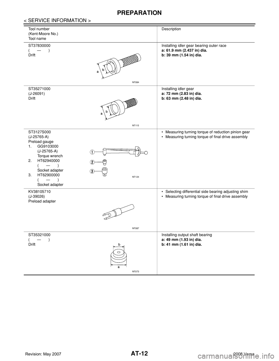
ST37830000
( — )
DriftInstalling idler gear bearing outer race
a: 61.9 mm (2.437 in) dia.
b: 39 mm (1.54 in) dia.
ST35271000
(J-26091)
DriftInstalling idler gear
a: 72 mm (2.83 in) dia.
b: 63 mm (2.48 in) dia.
ST3127S000
(J-25765-A)
Preload gauge
1. GG9103000
(J-25765-A)
Torque wrench
2. HT62940000
( — )
Socket adapter
3. HT62900000
( — )
Socket adapter• Measuring turning torque of reduction pinion gear
• Measuring turning torque of final drive assembly
KV38105710
(J-39026)
Preload adapter• Selecting differential side bearing adjusting shim
• Measuring turning torque of final drive assembly
ST35321000
( — )
DriftInstalling output shaft bearing
a: 49 mm (1.93 in) dia.
b: 41 mm (1.61 in) dia. Tool number
(Kent-Moore No.)
Tool nameDescription
NT084
NT115
NT124
NT087
NT073
Page 27 of 2771
A/T FLUID
AT-15
< SERVICE INFORMATION >
D
E
F
G
H
I
J
K
L
MA
B
AT
N
O
P
A/T FLUID
Checking A/T FluidINFOID:0000000001703158
1. Warm up engine.
2. Check for A/T fluid leakage.
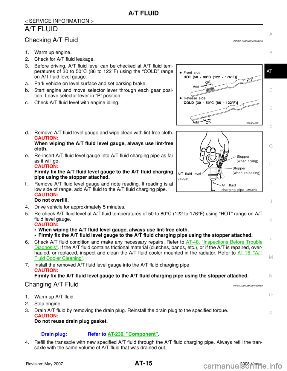
3. Before driving, A/T fluid level can be checked at A/T fluid tem-
peratures of 30 to 50°C (86 to 122°F) using the “COLD” range
on A/T fluid level gauge.
a. Park vehicle on level surface and set parking brake.
b. Start engine and move selector lever through each gear posi-
tion. Leave selector lever in “P” position.
c. Check A/T fluid level with engine idling.
d. Remove A/T fluid level gauge and wipe clean with lint-free cloth.
CAUTION:
When wiping the A/T fluid level gauge, always use lint-free
cloth.
e. Re-insert A/T fluid level gauge into A/T fluid charging pipe as far
as it will go.
CAUTION:
Firmly fix the A/T fluid level gauge to the A/T fluid charging
pipe using the stopper attached.
f. Remove A/T fluid level gauge and note reading. If reading is at
low side of range, add A/T fluid to the A/T fluid charging pipe.
CAUTION:
Do not overfill.
4. Drive vehicle for approximately 5 minutes.
5. Re-check A/T fluid level at A/T fluid temperatures of 50 to 80°C (122 to 176°F) using “HOT” range on A/T
fluid level gauge.
CAUTION:
• When wiping the A/T fluid level gauge, always use lint-free cloth.
• Firmly fix the A/T fluid level gauge to the A/T fluid charging pipe using the stopper attached.
6. Check A/T fluid condition and make any necessary repairs. Refer to AT-48, "
Inspections Before Trouble
Diagnosis". If the A/T fluid contains frictional material (clutches, bands, etc.), or if the A/T is repaired, over-
hauled, or replaced, inspect and clean the A/T fluid cooler mounted in the radiator. Refer to AT-16, "
A/T
Fluid Cooler Cleaning".
7. Install the removed A/T fluid level gauge into the A/T fluid charging pipe.
CAUTION:
Firmly fix the A/T fluid level gauge to the A/T fluid charging pipe using the stopper attached.
Changing A/T FluidINFOID:0000000001703159
1. Warm up A/T fluid.
2. Stop engine.
3. Drain A/T fluid by removing the drain plug. Reinstall the drain plug to the specified torque.
CAUTION:
Do not reuse drain plug gasket.
4. Refill the transaxle with new specified A/T fluid through the A/T fluid charging pipe. Always refill the tran-
saxle with the same volume of A/T fluid that was drained out.
SCIA3451E
SMA051D
Drain plug: Refer to AT-230, "Component".
Page 31 of 2771
A/T CONTROL SYSTEM
AT-19
< SERVICE INFORMATION >
D
E
F
G
H
I
J
K
L
MA
B
AT
N
O
P
A/T CONTROL SYSTEM
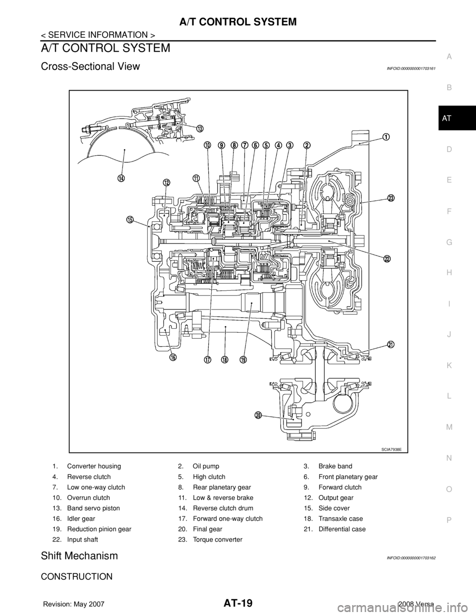
Cross-Sectional ViewINFOID:0000000001703161
Shift MechanismINFOID:0000000001703162
CONSTRUCTION
1. Converter housing 2. Oil pump 3. Brake band
4. Reverse clutch 5. High clutch 6. Front planetary gear
7. Low one-way clutch 8. Rear planetary gear 9. Forward clutch
10. Overrun clutch 11. Low & reverse brake 12. Output gear
13. Band servo piston 14. Reverse clutch drum 15. Side cover
16. Idler gear 17. Forward one-way clutch 18. Transaxle case
19. Reduction pinion gear 20. Final gear 21. Differential case
22. Input shaft 23. Torque converter
SCIA7938E
Page 32 of 2771
AT-20
< SERVICE INFORMATION >
A/T CONTROL SYSTEM
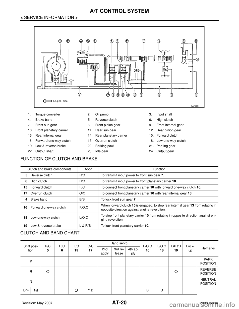
FUNCTION OF CLUTCH AND BRAKE
CLUTCH AND BAND CHART
1. Torque converter 2. Oil pump 3. Input shaft
4. Brake band 5. Reverse clutch 6. High clutch
7. Front sun gear 8. Front pinion gear 9. Front internal gear
10. Front planetary carrier 11. Rear sun gear 12. Rear pinion gear
13. Rear internal gear 14. Rear planetary carrier 15. Forward clutch
16. Forward one-way clutch 17. Overrun clutch 18. Low one-way clutch
19. Low & reverse brake 20. Parking pawl 21. Parking gear
22. Output shaft 23. Idle gear 24. Output gear
SAT998I
Clutch and brake components Abbr. Function
5Reverse clutch R/C To transmit input power to front sun gear 7.
6High clutch H/C To transmit input power to front planetary carrier 10.
15Forward clutch F/C To connect front planetary carrier 10 with forward one-way clutch 16.
17Overrun clutch O/C To connect front planetary carrier 10 with rear internal gear 13.
4Brake band B/B To lock front sun gear 7.
16Forward one-way clutch F/O.CWhen forward clutch 15 is engaged, to stop rear internal gear 13 from rotating in
opposite direction against engine revolution.
18Low one-way clutch L/O.CTo stop front planetary carrier 10 from rotating in opposite direction against en-
gine revolution.
19Low & reverse brake L & R/B To lock front planetary carrier 10.
Shift posi-
tionR/C
5H/C
6F/C
15O/C
17Band servo
F/O.C
16L/O.C
18L&R/B
19Lock-
upRemarks
2nd
apply3rd re-
lease4th ap-
ply
PPA R K
POSITION
RREVERSE
POSITION
NNEUTRAL
POSITION
D*4 1st *1D B B
Page 39 of 2771
A/T CONTROL SYSTEM
AT-27
< SERVICE INFORMATION >
D
E
F
G
H
I
J
K
L
MA
B
AT
N
O
P
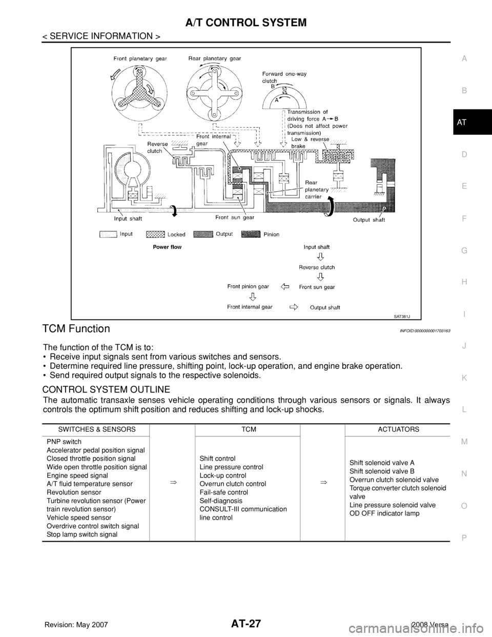
TCM FunctionINFOID:0000000001703163
The function of the TCM is to:
• Receive input signals sent from various switches and sensors.
• Determine required line pressure, shifting point, lock-up operation, and engine brake operation.
• Send required output signals to the respective solenoids.
CONTROL SYSTEM OUTLINE
The automatic transaxle senses vehicle operating conditions through various sensors or signals. It always
controls the optimum shift position and reduces shifting and lock-up shocks.
SAT381J
SWITCHES & SENSORS
⇒TCM
⇒ACTUATORS
PNP switch
Accelerator pedal position signal
Closed throttle position signal
Wide open throttle position signal
Engine speed signal
A/T fluid temperature sensor
Revolution sensor
Turbine revolution sensor (Power
train revolution sensor)
Vehicle speed sensor
Overdrive control switch signal
Stop lamp switch signalShift control
Line pressure control
Lock-up control
Overrun clutch control
Fail-safe control
Self-diagnosis
CONSULT-III communication
line controlShift solenoid valve A
Shift solenoid valve B
Overrun clutch solenoid valve
Torque converter clutch solenoid
valve
Line pressure solenoid valve
OD OFF indicator lamp
Page 41 of 2771
A/T CONTROL SYSTEM
AT-29
< SERVICE INFORMATION >
D
E
F
G
H
I
J
K
L
MA
B
AT
N
O
P
*1: Spare for vehicle speed sensor·A/T (revolution sensor)
*2: Spare for accelerator pedal position signal
*3: If these input and output signals are different, the TCM triggers the fail-safe function.
*4: Used as a condition for starting self-diagnostics; if self-diagnosis are not started, it is judged that there is some kind of error.
*5: Input by CAN communications.
*6: Output by CAN communications.
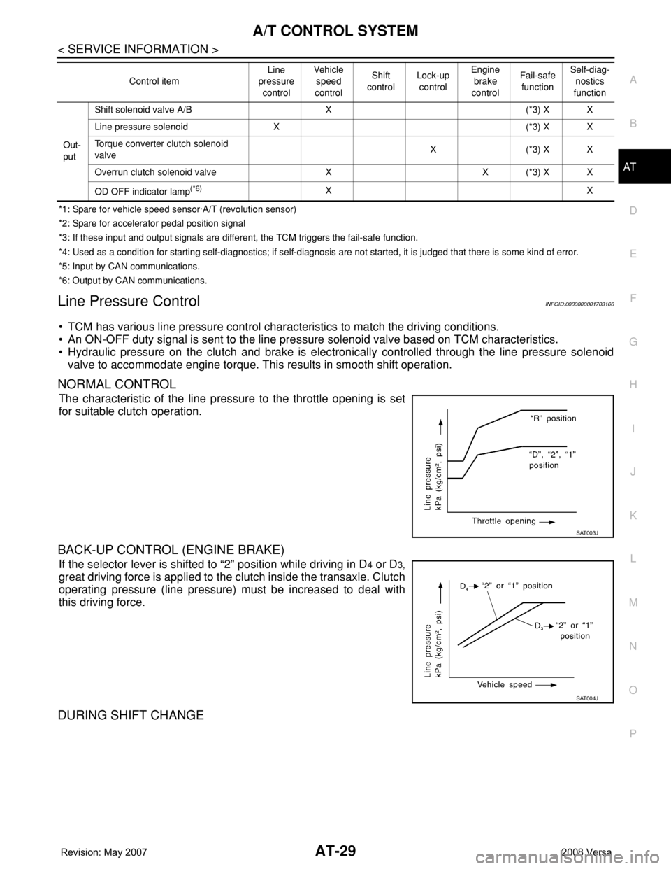
Line Pressure ControlINFOID:0000000001703166
• TCM has various line pressure control characteristics to match the driving conditions.
• An ON-OFF duty signal is sent to the line pressure solenoid valve based on TCM characteristics.
• Hydraulic pressure on the clutch and brake is electronically controlled through the line pressure solenoid
valve to accommodate engine torque. This results in smooth shift operation.
NORMAL CONTROL
The characteristic of the line pressure to the throttle opening is set
for suitable clutch operation.
BACK-UP CONTROL (ENGINE BRAKE)
If the selector lever is shifted to “2” position while driving in D4 or D3,
great driving force is applied to the clutch inside the transaxle. Clutch
operating pressure (line pressure) must be increased to deal with
this driving force.
DURING SHIFT CHANGE
Out-
putShift solenoid valve A/B X (*3) X X
Line pressure solenoid X (*3) X X
Torque converter clutch solenoid
valveX(*3) XX
Overrun clutch solenoid valve X X (*3) X X
OD OFF indicator lamp
(*6)XX Control itemLine
pressure
controlVeh icl e
speed
controlShift
controlLock-up
controlEngine
brake
controlFail-safe
functionSelf-diag-
nostics
function
SAT003J
SAT004J
Page 42 of 2771
AT-30
< SERVICE INFORMATION >
A/T CONTROL SYSTEM
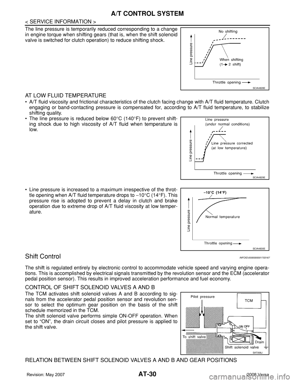
The line pressure is temporarily reduced corresponding to a change
in engine torque when shifting gears (that is, when the shift solenoid
valve is switched for clutch operation) to reduce shifting shock.
AT LOW FLUID TEMPERATURE
• A/T fluid viscosity and frictional characteristics of the clutch facing change with A/T fluid temperature. Clutch
engaging or band-contacting pressure is compensated for, according to A/T fluid temperature, to stabilize
shifting quality.
• The line pressure is reduced below 60°C (140°F) to prevent shift-
ing shock due to high viscosity of A/T fluid when temperature is
low.
• Line pressure is increased to a maximum irrespective of the throt-
tle opening when A/T fluid temperature drops to −10°C (14°F). This
pressure rise is adopted to prevent a delay in clutch and brake
operation due to extreme drop of A/T fluid viscosity at low temper-
ature.
Shift ControlINFOID:0000000001703167
The shift is regulated entirely by electronic control to accommodate vehicle speed and varying engine opera-
tions. This is accomplished by electrical signals transmitted by the revolution sensor and the ECM (accelerator
pedal position sensor). This results in improved acceleration performance and fuel economy.
CONTROL OF SHIFT SOLENOID VALVES A AND B
The TCM activates shift solenoid valves A and B according to sig-
nals from the accelerator pedal position sensor and revolution sen-
sor to select the optimum gear position on the basis of the shift
schedule memorized in the TCM.
The shift solenoid valve performs simple ON-OFF operation. When
set to “ON”, the drain circuit closes and pilot pressure is applied to
the shift valve.
RELATION BETWEEN SHIFT SOLENOID VALVES A AND B AND GEAR POSITIONS
SCIA4828E
SCIA4829E
SCIA4830E
SAT008J
Page 43 of 2771
A/T CONTROL SYSTEM
AT-31
< SERVICE INFORMATION >
D
E
F
G
H
I
J
K
L
MA
B
AT
N
O
P
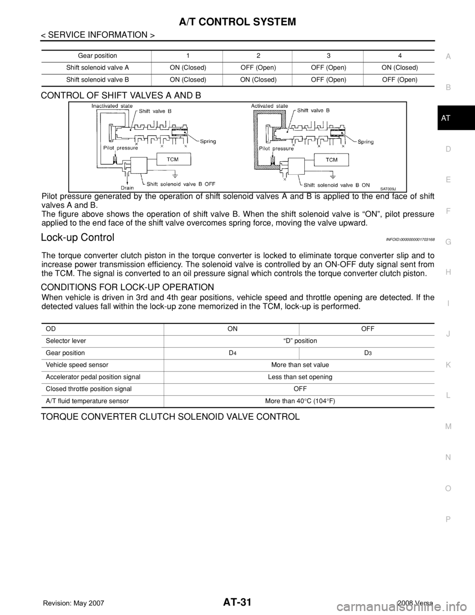
CONTROL OF SHIFT VALVES A AND B
Pilot pressure generated by the operation of shift solenoid valves A and B is applied to the end face of shift
valves A and B.
The figure above shows the operation of shift valve B. When the shift solenoid valve is “ON”, pilot pressure
applied to the end face of the shift valve overcomes spring force, moving the valve upward.
Lock-up ControlINFOID:0000000001703168
The torque converter clutch piston in the torque converter is locked to eliminate torque converter slip and to
increase power transmission efficiency. The solenoid valve is controlled by an ON-OFF duty signal sent from
the TCM. The signal is converted to an oil pressure signal which controls the torque converter clutch piston.
CONDITIONS FOR LOCK-UP OPERATION
When vehicle is driven in 3rd and 4th gear positions, vehicle speed and throttle opening are detected. If the
detected values fall within the lock-up zone memorized in the TCM, lock-up is performed.
TORQUE CONVERTER CLUTCH SOLENOID VALVE CONTROL
Gear position 1 2 3 4
Shift solenoid valve A ON (Closed) OFF (Open) OFF (Open) ON (Closed)
Shift solenoid valve B ON (Closed) ON (Closed) OFF (Open) OFF (Open)
SAT009J
OD ON OFF
Selector lever “D” position
Gear position D
4D3
Vehicle speed sensor More than set value
Accelerator pedal position signal Less than set opening
Closed throttle position signal OFF
A/T fluid temperature sensor More than 40°C (104°F)