150 NISSAN TIIDA 2008 Service Repair Manual
[x] Cancel search | Manufacturer: NISSAN, Model Year: 2008, Model line: TIIDA, Model: NISSAN TIIDA 2008Pages: 2771, PDF Size: 60.61 MB
Page 15 of 2771

AT-3
D
E
F
G
H
I
J
K
L
MA
B
AT
N
O
P N Wiring Diagram - AT - SSV/B ................................
140
Diagnosis Procedure .............................................141
Component Inspection ..........................................142
DTC P1760 OVERRUN CLUTCH SOLENOID
VALVE ..............................................................
144
Description ............................................................144
CONSULT-III Reference Value in Data Monitor
Mode .....................................................................
144
On Board Diagnosis Logic ....................................144
Possible Cause .....................................................144
DTC Confirmation Procedure ................................144
Wiring Diagram - AT - OVRCSV ...........................145
Diagnosis Procedure .............................................146
Component Inspection ..........................................147
DTC VEHICLE SPEED SENSOR MTR ............149
Description ............................................................149
CONSULT-III Reference Value in Data Monitor
Mode .....................................................................
149
On Board Diagnosis Logic ....................................149
Possible Cause .....................................................149
DTC Confirmation Procedure ................................149
Wiring Diagram - AT - VSSMTR ...........................150
Diagnosis Procedure .............................................151
DTC BATT/FLUID TEMP SEN (A/T FLUID
TEMP SENSOR CIRCUIT AND TCM POWER
SOURCE) .........................................................
152
Description ............................................................152
CONSULT-III Reference Value in Data Monitor
Mode .....................................................................
152
On Board Diagnosis Logic ....................................152
Possible Cause .....................................................152
DTC Confirmation Procedure ................................152
Wiring Diagram - AT - BA/FTS ..............................153
Diagnosis Procedure .............................................154
Component Inspection ..........................................156
DTC TURBINE REVOLUTION SENSOR .........158
Description ............................................................158
CONSULT-III Reference Value in Data Monitor
Mode .....................................................................
158
On Board Diagnosis Logic ....................................158
Possible Cause .....................................................158
DTC Confirmation Procedure ................................158
Wiring Diagram - AT - PT/SEN .............................159
Diagnosis Procedure .............................................160
CONTROL UNIT (RAM), CONTROL UNIT
(ROM) ...............................................................
163
Description ............................................................163
On Board Diagnosis Logic ....................................163
Possible Cause .....................................................163
DTC Confirmation Procedure ................................163
Diagnosis Procedure .............................................163
MAIN POWER SUPPLY AND GROUND CIR-
CUIT ..................................................................
164
Wiring Diagram - AT - MAIN .................................164
Diagnosis Procedure .............................................165
PNP, OD SWITCH AND CLOSED THROT-
TLE, WIDE OPEN THROTTLE POSITION
SIGNAL CIRCUIT ............................................
167
CONSULT-III Reference Value in Data Monitor
Mode ......................................................................
167
TCM Terminal and Reference Value .....................167
Diagnosis Procedure .............................................167
Component Inspection ...........................................171
SHIFT POSITION INDICATOR CIRCUIT ........172
Description .............................................................172
CONSULT-III Reference Value in Data Monitor
Mode ......................................................................
172
Diagnosis Procedure .............................................172
TROUBLE DIAGNOSIS FOR SYMPTOMS ....173
Wiring Diagram - AT - NONDTC ...........................173
OD OFF Indicator Lamp Does Not Come On ........176
Engine Cannot Be Started in "P" and "N" Position ..178
In "P" Position, Vehicle Moves Forward or Back-
ward When Pushed ...............................................
179
In "N" Position, Vehicle Moves ..............................179
Large Shock "N" → "R" Position ............................180
Vehicle Does Not Creep Backward in "R" Position ..181
Vehicle Does Not Creep Forward in "D", "2" or "1"
Position ..................................................................
182
Vehicle Cannot Be Started from D1 .......................183
A/T Does Not Shift: D1→ D2or Does Not Kick-
down: D
4→ D2 .......................................................185
A/T Does Not Shift: D2→ D3 ..................................186
A/T Does Not Shift: D3→ D4 ..................................188
A/T Does Not Perform Lock-up .............................189
A/T Does Not Hold Lock-up Condition ...................190
Lock-up Is Not Released .......................................191
Engine Speed Does Not Return to Idle (Light
Braking D
4→ D3) ...................................................192
A/T Does Not Shift: D4→ D3, When OD OFF ........193
A/T Does Not Shift: D3→ 22, When Selector Lever
"D" → "2" Position .................................................
194
A/T Does Not Shift: 22→ 11, When Selector Lever
"2" → "1" Position ..................................................
195
Vehicle Does Not Decelerate by Engine Brake .....197
TCM Self-Diagnosis Does Not Activate .................200
TRANSMISSION CONTROL MODULE ..........202
Removal and Installation .......................................202
SHIFT CONTROL SYSTEM ............................203
Control Device Removal and Installation ...............203
Control Device Disassembly and Assembly ..........206
Selector Lever Knob Removal and Installation ......206
Adjustment of A/T Position ....................................207
Checking of A/T Position .......................................207
A/T SHIFT LOCK SYSTEM .............................209
Description .............................................................209
Shift Lock System Parts Location ..........................209
Wiring Diagram - AT - SHIFT ................................210
Page 17 of 2771

INDEX FOR DTC
AT-5
< SERVICE INFORMATION >
D
E
F
G
H
I
J
K
L
MA
B
AT
N
O
P
SERVICE INFORMATION
INDEX FOR DTC
Alphabetical IndexINFOID:0000000001703149
NOTE:
If DTC “CAN COMM CIRCUIT” is displayed with other DTCs, first perform the trouble diagnosis for
DTC “CAN COMM CIRCUIT”. Refer to AT- 8 3
.
*1: These numbers is prescribed by SAE J2012.
*2: When the fail-safe operation occurs, the MIL illuminates.
*3: The MIL illuminates when both the “Revolution sensor signal” and the “Vehicle speed sensor signal” meet the fail-safe condition at
the same time.
DTC No. IndexINFOID:0000000001703150
NOTE:
If DTC “CAN COMM CIRCUIT” is displayed with other DTCs, first perform the trouble diagnosis for
DTC “CAN COMM CIRCUIT”. Refer to AT- 8 3
.
Items
(CONSULT-III screen terms)DTC
Reference page
CONSULT-III or GST
*1
A/T 1ST GR FNCTN P0731AT-105
A/T 2ND GR FNCTN P0732AT-108
A/T 3RD GR FNCTN P0733AT- 111
A/T 4TH GR FNCTN P0734AT- 11 4
A/T TCC S/V FNCTN P0744AT-124
ATF TEMP SEN/CIRC P0710AT- 9 1
BATT/FLUID TEMP SEN —AT-152
CAN COMM CIRCUIT U1000AT- 8 3
CONTROL UNIT (RAM) —AT-163
CONTROL UNIT (ROM) —AT-163
ENGINE SPEED SIG P0725AT-101
LINE PRESSURE S/V P0745AT-129
OVERRUN CLUTCH S/V P1760AT-144
PNP SW/CIRC P0705AT- 8 6
SHIFT SOLENOID/V A*2P0750AT-134
SHIFT SOLENOID/V B*2P0755AT-139
T/C CLUTCH SOL/V P0740AT- 11 9
TURBINE SENSOR —AT-158
VHCL SPEED SEN-A/T*3P0720AT- 9 6
VHCL SPEED SEN-MTR —AT-149
DTC
Items
(CONSULT-III screen terms) Reference page
CONSULT-III or GST
*1
P0705 PNP SW/CIRCAT- 8 6
P0710 ATF TEMP SEN/CIRCAT- 9 1
P0720
VHCL SPEED SEN-A/T*3AT- 9 6
P0725 ENGINE SPEED SIGAT- 1 0 1
P0731 A/T 1ST GR FNCTNAT- 1 0 5
Page 73 of 2771
TROUBLE DIAGNOSIS
AT-61
< SERVICE INFORMATION >
D
E
F
G
H
I
J
K
L
MA
B
AT
N
O
P
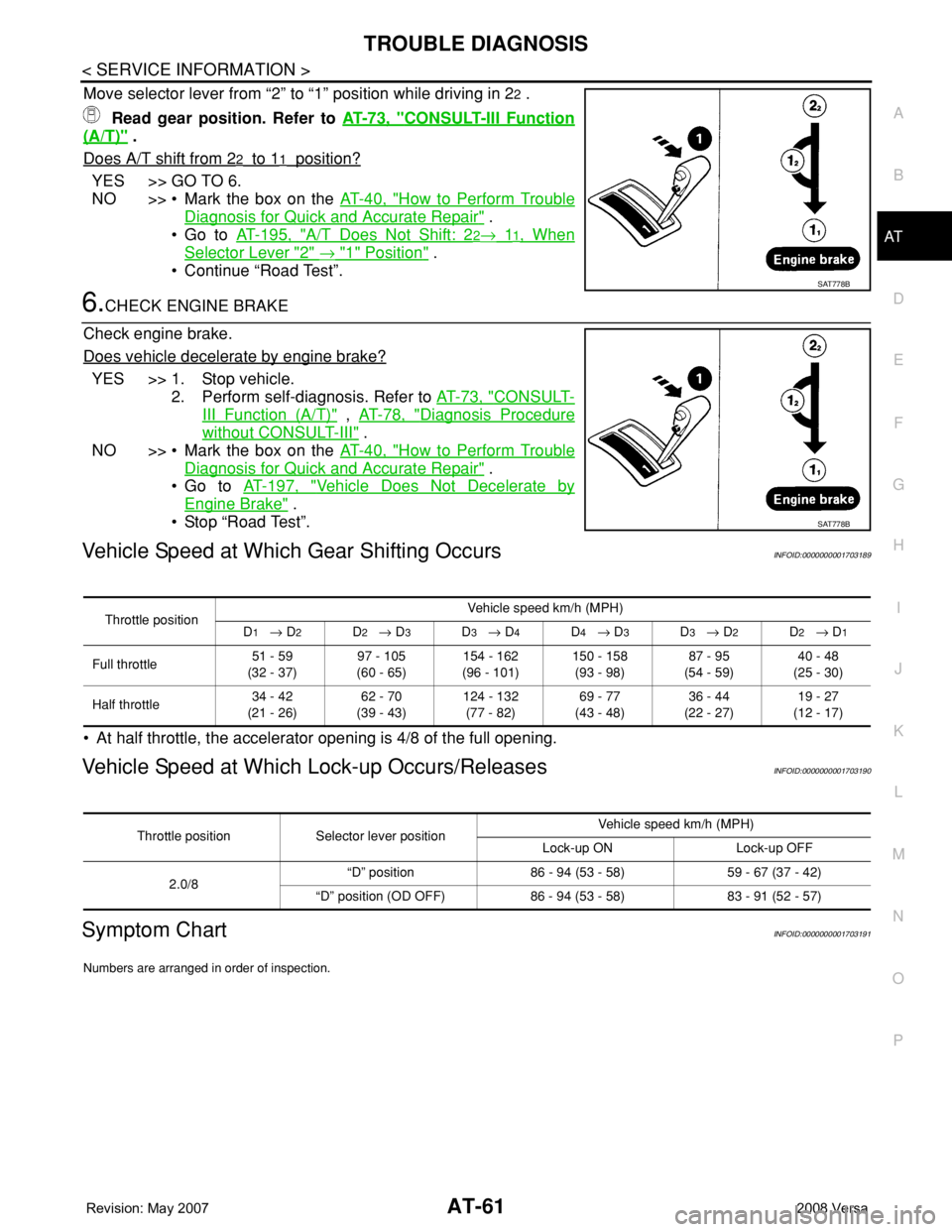
Move selector lever from “2” to “1” position while driving in 22 .
Read gear position. Refer to AT-73, "
CONSULT-III Function
(A/T)" .
Does A/T shift from 2
2 to 11 position?
YES >> GO TO 6.
NO >> • Mark the box on the AT-40, "
How to Perform Trouble
Diagnosis for Quick and Accurate Repair" .
•Go to AT-195, "
A/T Does Not Shift: 22→ 11, When
Selector Lever "2" → "1" Position" .
• Continue “Road Test”.
6.CHECK ENGINE BRAKE
Check engine brake.
Does vehicle decelerate by engine brake?
YES >> 1. Stop vehicle.
2. Perform self-diagnosis. Refer to AT-73, "
CONSULT-
III Function (A/T)" , AT-78, "Diagnosis Procedure
without CONSULT-III" .
NO >> • Mark the box on the AT-40, "
How to Perform Trouble
Diagnosis for Quick and Accurate Repair" .
•Go to AT-197, "
Vehicle Does Not Decelerate by
Engine Brake" .
• Stop “Road Test”.
Vehicle Speed at Which Gear Shifting OccursINFOID:0000000001703189
• At half throttle, the accelerator opening is 4/8 of the full opening.
Vehicle Speed at Which Lock-up Occurs/ReleasesINFOID:0000000001703190
Symptom ChartINFOID:0000000001703191
Numbers are arranged in order of inspection.
SAT778B
SAT778B
Throttle positionVehicle speed km/h (MPH)
D1 → D2D2 → D3D3 → D4D4 → D3D3 → D2D2 → D1
Full throttle51 - 59
(32 - 37)97 - 105
(60 - 65)154 - 162
(96 - 101)150 - 158
(93 - 98)87 - 95
(54 - 59)40 - 48
(25 - 30)
Half throttle34 - 42
(21 - 26)62 - 70
(39 - 43)124 - 132
(77 - 82)69 - 77
(43 - 48)36 - 44
(22 - 27)19 - 27
(12 - 17)
Throttle position Selector lever positionVehicle speed km/h (MPH)
Lock-up ON Lock-up OFF
2.0/8“D” position 86 - 94 (53 - 58) 59 - 67 (37 - 42)
“D” position (OD OFF) 86 - 94 (53 - 58) 83 - 91 (52 - 57)
Page 84 of 2771
AT-72
< SERVICE INFORMATION >
TROUBLE DIAGNOSIS
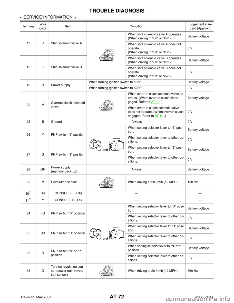
11 O Shift solenoid valve AWhen shift solenoid valve A operates.
(When driving in “D
1” or “D4”.)Battery voltage
When shift solenoid valve A does not
operate.
(When driving in “D
2” or “D3”.)0 V
12 G Shift solenoid valve BWhen shift solenoid valve B operates.
(When driving in “D
1” or “D2”.)Battery voltage
When shift solenoid valve B does not
operate.
(When driving in “D
3” or “D4”.)0 V
19 R Power supplyWhen turning ignition switch to “ON”. Battery voltage
When turning ignition switch to “OFF”. 0 V
20 VOverrun clutch solenoid
valveWhen overrun clutch solenoid valve op-
erates. (When overrun clutch disen-
gaged. Refer to AT- 1 9
.)Battery voltage
When overrun clutch solenoid valve
does not operate. (When overrun clutch
engaged. Refer to AT- 1 9
.)0 V
25 B Ground Always 0 V
26 Y PNP switch “1” position
and When setting selector lever to “1” posi-
tion.Battery voltage
When setting selector lever to other po-
sitions.0 V
27 G PNP switch “2” positionWhen setting selector lever to “2” posi-
tion.Battery voltage
When setting selector lever to other po-
sitions.0 V
28 GRPower supply
(memory back-up)Always Battery voltage
29 V Revolution sensor When driving at 20 km/h (12 MPH) 150 Hz
30
*1BR CONSULT- III (RX) — —
31
*1Y CONSULT- III (TX) — —
34 LG PNP switch “D” position
and When setting selector lever to “D” posi-
tion.Battery voltage
When setting selector lever to other po-
sitions.0 V
35 SB PNP switch “R” positionWhen setting selector lever to “R” posi-
tion.Battery voltage
When setting selector lever to other po-
sitions.0 V
36 RPNP switch “N” or “P”
positionWhen setting selector lever to “N” or “P”
position.Battery voltage
When setting selector lever to other po-
sitions.0 V
38 GTurbine revolution sen-
sor (power train revolu-
tion sensor)When driving at 20 km/h (12 MPH) 360 Hz Te r m i n a lWire
colorItem ConditionJudgement stan-
dard (Approx.)
Page 110 of 2771
AT-98
< SERVICE INFORMATION >
DTC P0720 VEHICLE SPEED SENSOR A/T (REVOLUTION SENSOR)
TCM TERMINALS AND REFERENCE VALUES
Refer to AT-71, "TCM Terminal and Reference Value".
Diagnosis ProcedureINFOID:0000000001703223
1.CHECK INPUT SIGNAL
With CONSULT-III
1. Start engine.
2. Select “TCM INPUT SIGNALS” in “DATA MONITOR” mode for “A/T” with CONSULT-III.
3. Read out the value of “VHCL/S SE-A/T” while driving.
Check the value changes according to driving speed.
OK or NG
OK >> GO TO 8.
NG >> GO TO 2.
2. CHECK REVOLUTION SENSOR
With CONSULT-III
1. Start engine.
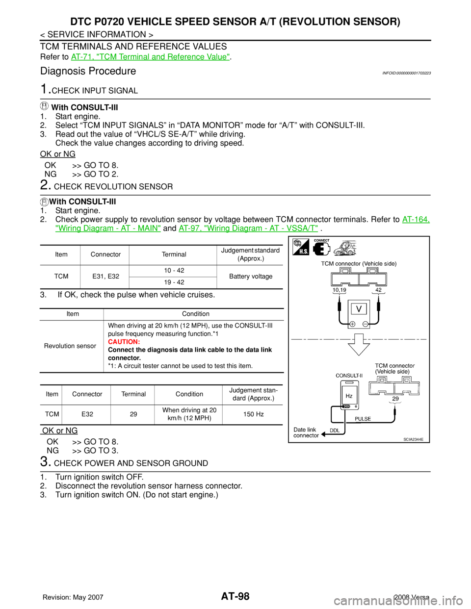
2. Check power supply to revolution sensor by voltage between TCM connector terminals. Refer to AT-164,
"Wiring Diagram - AT - MAIN" and AT-97, "Wiring Diagram - AT - VSSA/T" .
3. If OK, check the pulse when vehicle cruises.
OK or NG
OK >> GO TO 8.
NG >> GO TO 3.
3. CHECK POWER AND SENSOR GROUND
1. Turn ignition switch OFF.
2. Disconnect the revolution sensor harness connector.
3. Turn ignition switch ON. (Do not start engine.)
Item Connector TerminalJudgement standard
(Approx.)
TCM E31, E3210 - 42
Battery voltage
19 - 42
Item Condition
Revolution sensorWhen driving at 20 km/h (12 MPH), use the CONSULT-III
pulse frequency measuring function.*1
CAUTION:
Connect the diagnosis data link cable to the data link
connector.
*1: A circuit tester cannot be used to test this item.
Item Connector Terminal ConditionJudgement stan-
dard (Approx.)
TCM E32 29When driving at 20
km/h (12 MPH)150 Hz
SCIA2344E
Page 162 of 2771
AT-150
< SERVICE INFORMATION >
DTC VEHICLE SPEED SENSOR MTR
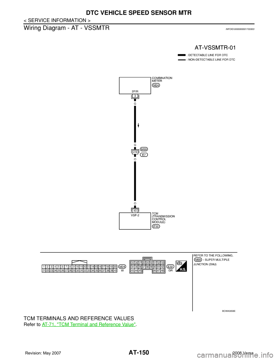
Wiring Diagram - AT - VSSMTR
INFOID:0000000001703303
TCM TERMINALS AND REFERENCE VALUES
Refer to AT-71, "TCM Terminal and Reference Value".
BCWA0658E
Page 229 of 2771
ON-VEHICLE SERVICE
AT-217
< SERVICE INFORMATION >
D
E
F
G
H
I
J
K
L
MA
B
AT
N
O
P
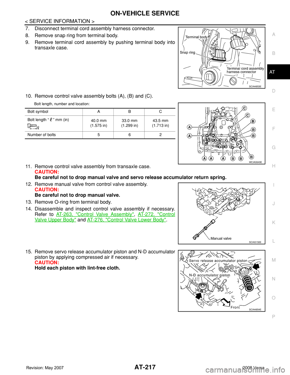
7. Disconnect terminal cord assembly harness connector.
8. Remove snap ring from terminal body.
9. Remove terminal cord assembly by pushing terminal body into
transaxle case.
10. Remove control valve assembly bolts (A), (B) and (C).
Bolt length, number and location:
11. Remove control valve assembly from transaxle case.
CAUTION:
Be careful not to drop manual valve and servo release accumulator return spring.
12. Remove manual valve from control valve assembly.
CAUTION:
Be careful not to drop manual valve.
13. Remove O-ring from terminal body.
14. Disassemble and inspect control valve assembly if necessary.
Refer to AT-263, "
Control Valve Assembly", AT-272, "Control
Valve Upper Body" and AT-276, "Control Valve Lower Body".
15. Remove servo release accumulator piston and N-D accumulator
piston by applying compressed air if necessary.
CAUTION:
Hold each piston with lint-free cloth.
SCIA4853E
Bolt symbol A B C
Bolt length “ ” mm (in)
40.0 mm
(1.575 in)33.0 mm
(1.299 in)43.5 mm
(1.713 in)
Number of bolts 5 6 2
WCIA0649E
SCIA3150E
SCIA4854E
Page 255 of 2771
DISASSEMBLY
AT-243
< SERVICE INFORMATION >
D
E
F
G
H
I
J
K
L
MA
B
AT
N
O
P
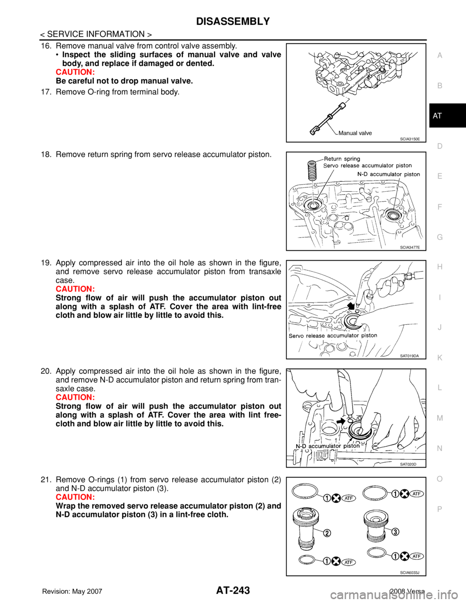
16. Remove manual valve from control valve assembly.
•Inspect the sliding surfaces of manual valve and valve
body, and replace if damaged or dented.
CAUTION:
Be careful not to drop manual valve.
17. Remove O-ring from terminal body.
18. Remove return spring from servo release accumulator piston.
19. Apply compressed air into the oil hole as shown in the figure,
and remove servo release accumulator piston from transaxle
case.
CAUTION:
Strong flow of air will push the accumulator piston out
along with a splash of ATF. Cover the area with lint-free
cloth and blow air little by little to avoid this.
20. Apply compressed air into the oil hole as shown in the figure,
and remove N-D accumulator piston and return spring from tran-
saxle case.
CAUTION:
Strong flow of air will push the accumulator piston out
along with a splash of ATF. Cover the area with lint free-
cloth and blow air little by little to avoid this.
21. Remove O-rings (1) from servo release accumulator piston (2)
and N-D accumulator piston (3).
CAUTION:
Wrap the removed servo release accumulator piston (2) and
N-D accumulator piston (3) in a lint-free cloth.
SCIA3150E
SCIA3477E
SAT019DA
SAT020D
SCIA6033J
Page 353 of 2771

SERVICE DATA AND SPECIFICATIONS (SDS)
AT-341
< SERVICE INFORMATION >
D
E
F
G
H
I
J
K
L
MA
B
AT
N
O
P
SERVICE DATA AND SPECIFICATIONS (SDS)
General SpecificationINFOID:0000000001703396
*: Refer to MA-10.
Vehicle Speed at Which Gear Shifting OccursINFOID:0000000001703397
• At half throttle, the accelerator opening is 4/8 of the full opening.
Vehicle Speed at When Lock-up Occurs/ReleasesINFOID:0000000001703398
Stall SpeedINFOID:0000000001703399
Line PressureINFOID:0000000001703400
Adjusting shims, Needle Bearings, Thrust Washers and Snap RingsINFOID:0000000001703401
NOTE:
EngineMR18DE
Automatic transaxle model RE4F03B
Automatic transaxle assembly Model code number 3CX0D
Transaxle gear ratio1st 2.861
2nd 1.562
3rd 1.000
4th 0.697
Reverse 2.310
Final drive 4.072
Recommended fluidGenuine NISSAN Matic D ATF (Continental U.S. and Alaska) or
Canada NISSAN Automatic Transmission Fluid*
Fluid capacity [ (US qt, Imp qt)]7.9 (8-3/8, 7)
Throttle positionVehicle speed km/h (MPH)
D1 → D2D2 → D3D3 → D4D4 → D3D3 → D2D2 → D1
Full throttle51 - 59
(32 - 37)97 - 105
(60 - 65)154 - 162
(96 - 101)150 - 158
(93 - 98)87 - 95
(54 - 59)40 - 48
(25 - 30)
Half throttle34 - 42
(21 - 26)62 - 70
(39 - 43)124 - 132
(77 - 82)69 - 77
(43 - 48)36 - 44
(22 - 27)19 - 27
(12 - 17)
Throttle position Selector lever positionVehicle speed km/h (MPH)
Lock-up ON Lock-up OFF
2.0/8“D” position 86 - 94 (53 - 58) 59 - 67 (37 - 42)
“D” position (OD OFF) 86 - 94 (53 - 58) 83 - 91 (52 - 57)
Stall revolution (rpm)2,310 - 2,770
Engine speedLine pressure kPa (kg/cm2, psi)
“D”, “2” and “1” positions “R” position
Idle speed 500 (5.1, 73) 778 (7.9, 113)
Stall speed 1,173 (12.0, 170) 1,825 (18.6, 265)
Page 359 of 2771

SERVICE DATA AND SPECIFICATIONS (SDS)
AT-347
< SERVICE INFORMATION >
D
E
F
G
H
I
J
K
L
MA
B
AT
N
O
P
A/T Fluid Temperature SensorINFOID:0000000001703418
Remarks: Specification data are reference values.
Revolution SensorINFOID:0000000001703419
Dropping ResistorINFOID:0000000001703420
Turbine Revolution Sensor (Power Train Revolution Sensor)INFOID:0000000001703421
Condition Specification (Approx.)
Cold [20°C (68°F)]
↓
Hot [80°C (176°F)]1.5V
↓
0.5V2.5 kΩ
↓
0.3 kΩ
Condition Judgment standard
When driving at 20 km/h (12 MPH) 150 Hz (Approx.)
Resistance12Ω (Approx.)
Condition Judgment standard
When driving at 20 km/h (12 MPH) 360 Hz (Approx.)