360 NISSAN TIIDA 2008 Service Repair Manual
[x] Cancel search | Manufacturer: NISSAN, Model Year: 2008, Model line: TIIDA, Model: NISSAN TIIDA 2008Pages: 2771, PDF Size: 60.61 MB
Page 84 of 2771
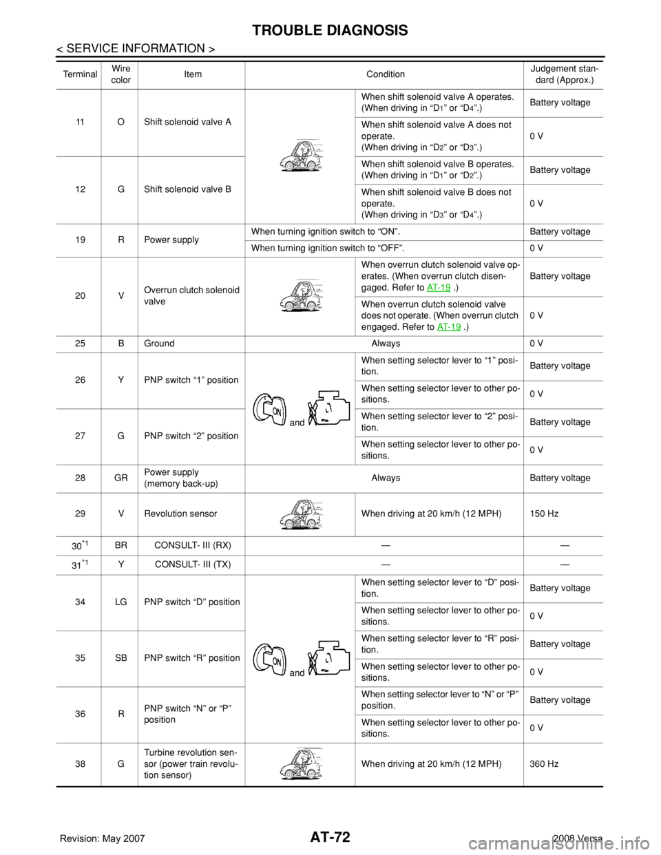
AT-72
< SERVICE INFORMATION >
TROUBLE DIAGNOSIS
11 O Shift solenoid valve AWhen shift solenoid valve A operates.
(When driving in “D
1” or “D4”.)Battery voltage
When shift solenoid valve A does not
operate.
(When driving in “D
2” or “D3”.)0 V
12 G Shift solenoid valve BWhen shift solenoid valve B operates.
(When driving in “D
1” or “D2”.)Battery voltage
When shift solenoid valve B does not
operate.
(When driving in “D
3” or “D4”.)0 V
19 R Power supplyWhen turning ignition switch to “ON”. Battery voltage
When turning ignition switch to “OFF”. 0 V
20 VOverrun clutch solenoid
valveWhen overrun clutch solenoid valve op-
erates. (When overrun clutch disen-
gaged. Refer to AT- 1 9
.)Battery voltage
When overrun clutch solenoid valve
does not operate. (When overrun clutch
engaged. Refer to AT- 1 9
.)0 V
25 B Ground Always 0 V
26 Y PNP switch “1” position
and When setting selector lever to “1” posi-
tion.Battery voltage
When setting selector lever to other po-
sitions.0 V
27 G PNP switch “2” positionWhen setting selector lever to “2” posi-
tion.Battery voltage
When setting selector lever to other po-
sitions.0 V
28 GRPower supply
(memory back-up)Always Battery voltage
29 V Revolution sensor When driving at 20 km/h (12 MPH) 150 Hz
30
*1BR CONSULT- III (RX) — —
31
*1Y CONSULT- III (TX) — —
34 LG PNP switch “D” position
and When setting selector lever to “D” posi-
tion.Battery voltage
When setting selector lever to other po-
sitions.0 V
35 SB PNP switch “R” positionWhen setting selector lever to “R” posi-
tion.Battery voltage
When setting selector lever to other po-
sitions.0 V
36 RPNP switch “N” or “P”
positionWhen setting selector lever to “N” or “P”
position.Battery voltage
When setting selector lever to other po-
sitions.0 V
38 GTurbine revolution sen-
sor (power train revolu-
tion sensor)When driving at 20 km/h (12 MPH) 360 Hz Te r m i n a lWire
colorItem ConditionJudgement stan-
dard (Approx.)
Page 172 of 2771
AT-160
< SERVICE INFORMATION >
DTC TURBINE REVOLUTION SENSOR
Diagnosis Procedure
INFOID:0000000001703319
1.CHECK INPUT SIGNAL
With CONSULT-III
1. Start engine.
2. Select “TCM INPUT SIGNALS” in “DATA MONITOR” mode for “A/T” with CONSULT-III.
3. Read out the value of “TURBINE REV” while driving. Check the value changes according to driving
speed.
OK or NG
OK >> GO TO 8.
NG >> GO TO 2.
2. CHECK TURBINE REVOLUTION SENSOR (POWER TRAIN REVOLUTION SENSOR)
With CONSULT-III
1. Start engine.
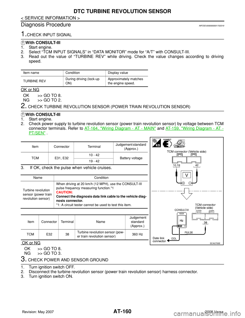
2. Check power supply to turbine revolution sensor (power train revolution sensor) by voltage between TCM
connector terminals. Refer to AT-164, "
Wiring Diagram - AT - MAIN" and AT-159, "Wiring Diagram - AT -
PT/SEN" .
3. If OK, check the pulse when vehicle cruises.
OK or NG
OK >> GO TO 8.
NG >> GO TO 3.
3. CHECK POWER AND SENSOR GROUND
1. Turn ignition switch OFF.
2. Disconnect the turbine revolution sensor (power train revolution sensor) harness connector.
3. Turn ignition switch ON.
Item name Condition Display value
TURBINE REV During driving (lock-up
ON)Approximately matches
the engine speed.
Item Connector TerminalJudgement standard
(Approx.)
TCM E31, E3210 - 42
Battery voltage
19 - 42
Name Condition
Turbine revolution
sensor (power train
revolution sensor)When driving at 20 km/h (12 MPH), use the CONSULT-III
pulse frequency measuring function.*1
CAUTION:
Connect the diagnosis data link cable to the vehicle diag-
nosis connector.
*1: A circuit tester cannot be used to test this item.
Item Connector Terminal Name Judgement
standard
(Approx.)
TCM E32 38Turbine revolution sensor (pow-
er train revolution sensor)360 Hz
SCIA2769E
Page 219 of 2771
SHIFT CONTROL SYSTEM
AT-207
< SERVICE INFORMATION >
D
E
F
G
H
I
J
K
L
MA
B
AT
N
O
P
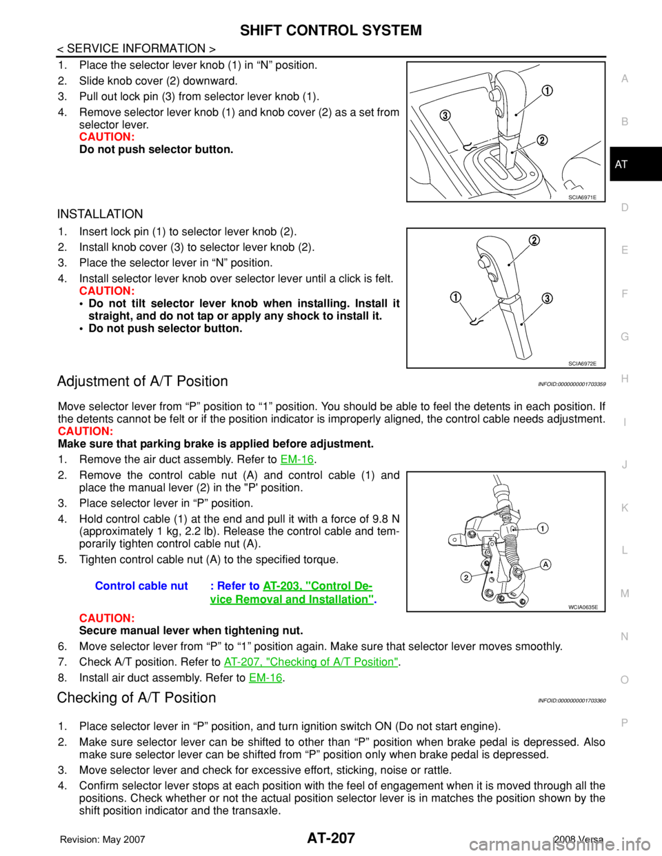
1. Place the selector lever knob (1) in “N” position.
2. Slide knob cover (2) downward.
3. Pull out lock pin (3) from selector lever knob (1).
4. Remove selector lever knob (1) and knob cover (2) as a set from
selector lever.
CAUTION:
Do not push selector button.
INSTALLATION
1. Insert lock pin (1) to selector lever knob (2).
2. Install knob cover (3) to selector lever knob (2).
3. Place the selector lever in “N” position.
4. Install selector lever knob over selector lever until a click is felt.
CAUTION:
• Do not tilt selector lever knob when installing. Install it
straight, and do not tap or apply any shock to install it.
• Do not push selector button.
Adjustment of A/T PositionINFOID:0000000001703359
Move selector lever from “P” position to “1” position. You should be able to feel the detents in each position. If
the detents cannot be felt or if the position indicator is improperly aligned, the control cable needs adjustment.
CAUTION:
Make sure that parking brake is applied before adjustment.
1. Remove the air duct assembly. Refer to EM-16
.
2. Remove the control cable nut (A) and control cable (1) and
place the manual lever (2) in the "P' position.
3. Place selector lever in “P” position.
4. Hold control cable (1) at the end and pull it with a force of 9.8 N
(approximately 1 kg, 2.2 lb). Release the control cable and tem-
porarily tighten control cable nut (A).
5. Tighten control cable nut (A) to the specified torque.
CAUTION:
Secure manual lever when tightening nut.
6. Move selector lever from “P” to “1” position again. Make sure that selector lever moves smoothly.
7. Check A/T position. Refer to AT-207, "
Checking of A/T Position".
8. Install air duct assembly. Refer to EM-16
.
Checking of A/T PositionINFOID:0000000001703360
1. Place selector lever in “P” position, and turn ignition switch ON (Do not start engine).
2. Make sure selector lever can be shifted to other than “P” position when brake pedal is depressed. Also
make sure selector lever can be shifted from “P” position only when brake pedal is depressed.
3. Move selector lever and check for excessive effort, sticking, noise or rattle.
4. Confirm selector lever stops at each position with the feel of engagement when it is moved through all the
positions. Check whether or not the actual position selector lever is in matches the position shown by the
shift position indicator and the transaxle.
SCIA6971E
SCIA6972E
Control cable nut : Refer to AT-203, "Control De-
vice Removal and Installation".WCIA0635E
Page 359 of 2771

SERVICE DATA AND SPECIFICATIONS (SDS)
AT-347
< SERVICE INFORMATION >
D
E
F
G
H
I
J
K
L
MA
B
AT
N
O
P
A/T Fluid Temperature SensorINFOID:0000000001703418
Remarks: Specification data are reference values.
Revolution SensorINFOID:0000000001703419
Dropping ResistorINFOID:0000000001703420
Turbine Revolution Sensor (Power Train Revolution Sensor)INFOID:0000000001703421
Condition Specification (Approx.)
Cold [20°C (68°F)]
↓
Hot [80°C (176°F)]1.5V
↓
0.5V2.5 kΩ
↓
0.3 kΩ
Condition Judgment standard
When driving at 20 km/h (12 MPH) 150 Hz (Approx.)
Resistance12Ω (Approx.)
Condition Judgment standard
When driving at 20 km/h (12 MPH) 360 Hz (Approx.)
Page 374 of 2771
AUDIO
AV-15
< SERVICE INFORMATION >
C
D
E
F
G
H
I
J
L
MA
B
AV
N
O
P
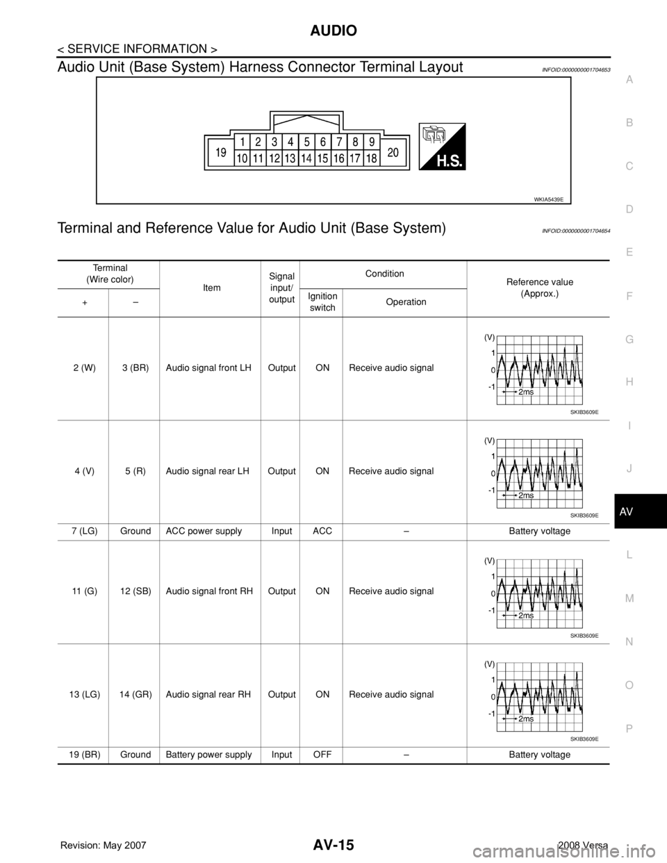
Audio Unit (Base System) Harness Connector Terminal LayoutINFOID:0000000001704653
Terminal and Reference Value for Audio Unit (Base System)INFOID:0000000001704654
WKIA5439E
Te r m i n a l
(Wire color)
ItemSignal
input/
outputCondition
Reference value
(Approx.)
+–Ignition
switchOperation
2 (W) 3 (BR) Audio signal front LH Output ON Receive audio signal
4 (V) 5 (R) Audio signal rear LH Output ON Receive audio signal
7 (LG) Ground ACC power supply Input ACC – Battery voltage
11 (G) 12 (SB) Audio signal front RH Output ON Receive audio signal
13 (LG) 14 (GR) Audio signal rear RH Output ON Receive audio signal
19 (BR) Ground Battery power supply Input OFF – Battery voltage
SKIB3609E
SKIB3609E
SKIB3609E
SKIB3609E
Page 376 of 2771
AUDIO
AV-17
< SERVICE INFORMATION >
C
D
E
F
G
H
I
J
L
MA
B
AV
N
O
P
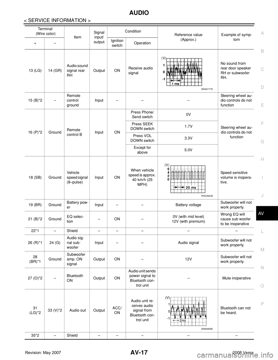
13 (LG) 14 (GR)Audio sound
signal rear
RHOutput ONReceive audio
signalNo sound from
rear door speaker
RH or subwoofer
RH.
15 (B)*2 –Remote
control
groundInput – – –Steering wheel au-
dio controls do not
function
16 (P)*2 GroundRemote
control BInput ONPress Phone/
Send switch0V
Steering wheel au-
dio controls do not
function Press SEEK
DOWN switch1.7V
Press VOL
DOWN switch3.3V
Except for
above5.0V
18 (SB) GroundVehicle
speed signal
(8–pulse)Input ONWhen vehicle
speed is approx.
40 km/h (25
MPH)Speed sensitive
volume is inopera-
tive.
19 (BR) GroundBattery pow-
erInput – – Battery voltageSubwoofer will not
work properly.
21 (B)*2 GroundEQ selec-
tion–ON –0V (with mid level)
12V (with premium)Wrong EQ will
cause sub woofer
to be inoperative
22*1 – Shield – – – – –
26 (R)*1 24 (G)Audio sig-
nal sub-
wooferInput – – Audio signalSubwoofer will not
work properly.
28
(BR)*1GroundSubwoofer
amp. ON
signalOutput ON – 12VSubwoofer will not
work properly.
27 (O)*2 –Bluetooth
ONOutput ONAudio unit sends
power signal to
Bluetooth con-
trol unit– Mute inoperative
31
(LG)*233 (V)*2 Audio out OutputACC/
ONAudio unit re-
ceives audio
signal from
Bluetooth con-
trol unitBluetooth can not
be heard.
35*2 – Shield – – – – –Te r m i n a l
(Wire color)
ItemSignal
input/
outputCondition
Reference value
(Approx.)Example of symp-
tom
+–Ignition
switchOperation
SKIA0177E
PKIC0643E
SKIB3609E
Page 378 of 2771
AUDIO
AV-19
< SERVICE INFORMATION >
C
D
E
F
G
H
I
J
L
MA
B
AV
N
O
P
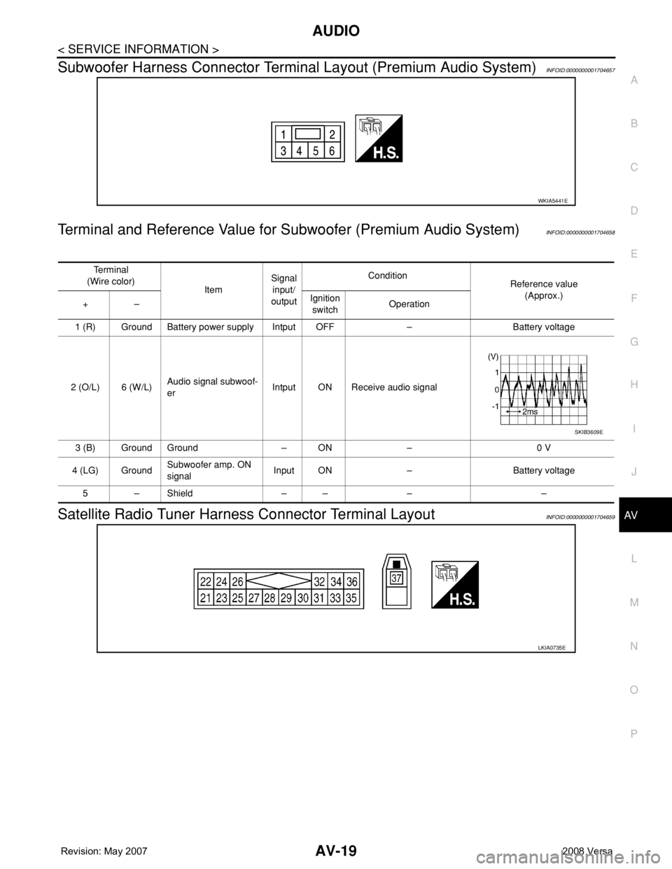
Subwoofer Harness Connector Terminal Layout (Premium Audio System)INFOID:0000000001704657
Terminal and Reference Value for Subwoofer (Premium Audio System)INFOID:0000000001704658
Satellite Radio Tuner Harness Connector Terminal LayoutINFOID:0000000001704659
WKIA5441E
Te r m i n a l
(Wire color)
ItemSignal
input/
outputCondition
Reference value
(Approx.)
+–Ignition
switchOperation
1 (R) Ground Battery power supply Intput OFF – Battery voltage
2 (O/L) 6 (W/L)Audio signal subwoof-
erIntput ON Receive audio signal
3 (B) Ground Ground – ON – 0 V
4 (LG) GroundSubwoofer amp. ON
signalInput ON – Battery voltage
5–Shield –– – –
SKIB3609E
LKIA0735E
Page 379 of 2771
AV-20
< SERVICE INFORMATION >
AUDIO
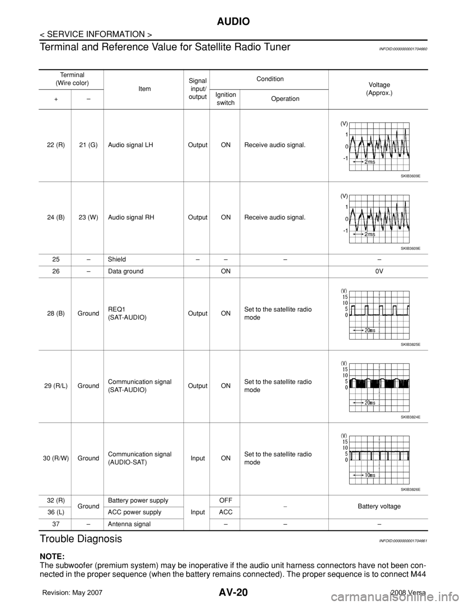
Terminal and Reference Value for Satellite Radio Tuner
INFOID:0000000001704660
Trouble DiagnosisINFOID:0000000001704661
NOTE:
The subwoofer (premium system) may be inoperative if the audio unit harness connectors have not been con-
nected in the proper sequence (when the battery remains connected). The proper sequence is to connect M44
Te r m i n a l
(Wire color)
ItemSignal
input/
outputCondition
Vol tag e
(Approx.)
+–Ignition
switchOperation
22 (R) 21 (G) Audio signal LH Output ON Receive audio signal.
24 (B) 23 (W) Audio signal RH Output ON Receive audio signal.
25 – Shield – – – –
26 – Data ground ON 0V
28 (B) GroundREQ1
(SAT-AUDIO)Output ONSet to the satellite radio
mode
29 (R/L) GroundCommunication signal
(SAT-AUDIO)Output ONSet to the satellite radio
mode
30 (R/W) GroundCommunication signal
(AUDIO-SAT)Input ONSet to the satellite radio
mode
32 (R)
GroundBattery power supply
InputOFF
−Battery voltage
36 (L) ACC power supply ACC
37 – Antenna signal – – –
SKIB3609E
SKIB3609E
SKIB3825E
SKIB3824E
SKIB3826E
Page 406 of 2771
TELEPHONE
AV-47
< SERVICE INFORMATION >
C
D
E
F
G
H
I
J
L
MA
B
AV
N
O
P
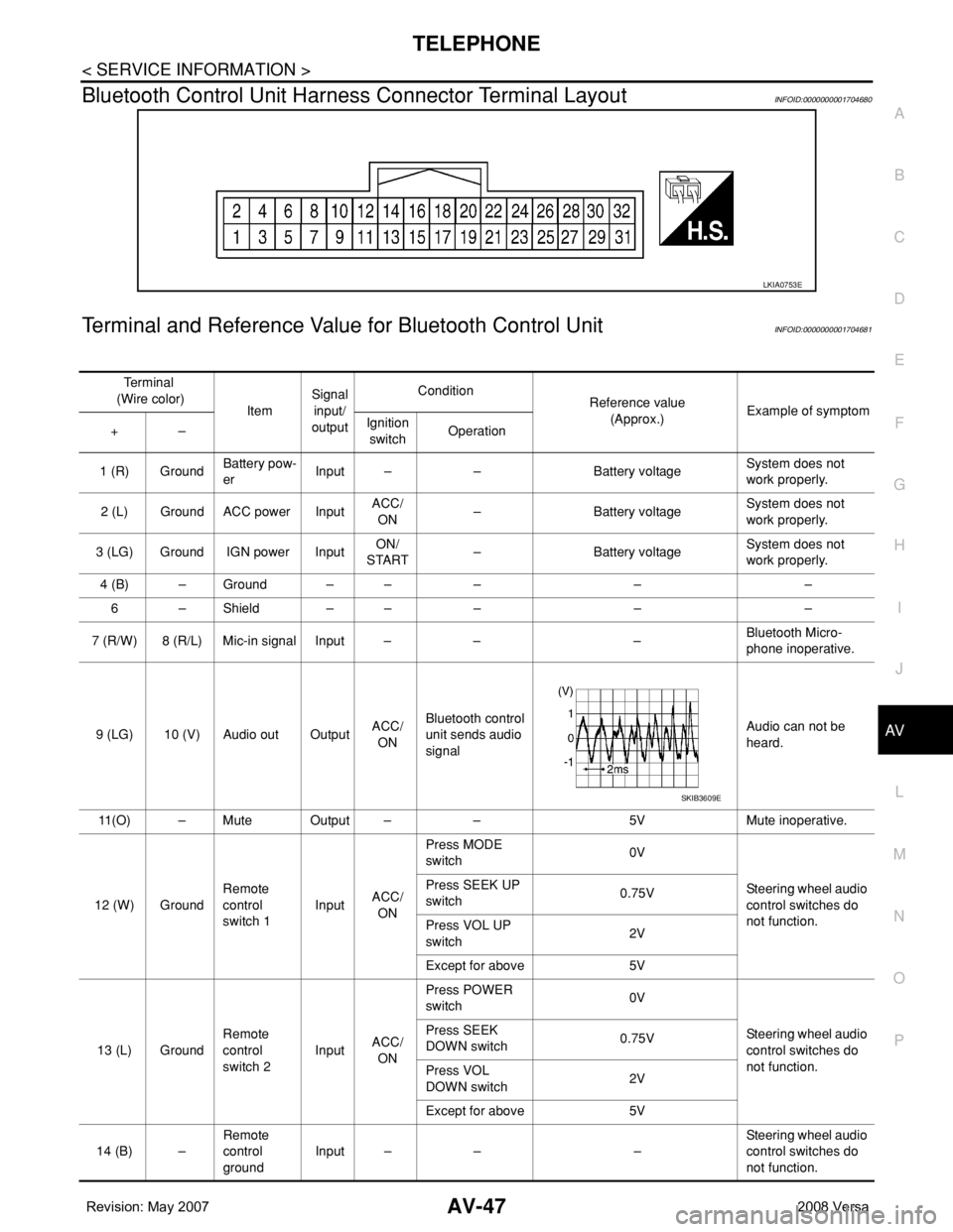
Bluetooth Control Unit Harness Connector Terminal LayoutINFOID:0000000001704680
Terminal and Reference Value for Bluetooth Control UnitINFOID:0000000001704681
LKIA0753E
Te r m i n a l
(Wire color)
ItemSignal
input/
outputCondition
Reference value
(Approx.)Example of symptom
+–Ignition
switchOperation
1 (R) GroundBattery pow-
erInput – – Battery voltageSystem does not
work properly.
2 (L) Ground ACC power InputACC/
ON– Battery voltageSystem does not
work properly.
3 (LG) Ground IGN power InputON/
START– Battery voltageSystem does not
work properly.
4 (B) – Ground – – – – –
6 – Shield – – – – –
7 (R/W) 8 (R/L) Mic-in signal Input – – –Bluetooth Micro-
phone inoperative.
9 (LG) 10 (V) Audio out OutputACC/
ONBluetooth control
unit sends audio
signalAudio can not be
heard.
11(O) – Mute Output – – 5V Mute inoperative.
12 (W) GroundRemote
control
switch 1InputACC/
ONPress MODE
switch 0V
Steering wheel audio
control switches do
not function. Press SEEK UP
switch0.75V
Press VOL UP
switch2V
Except for above 5V
13 (L) GroundRemote
control
switch 2InputACC/
ONPress POWER
switch 0V
Steering wheel audio
control switches do
not function. Press SEEK
DOWN switch0.75V
Press VOL
DOWN switch2V
Except for above 5V
14 (B) –Remote
control
groundInput – – –Steering wheel audio
control switches do
not function.
SKIB3609E
Page 413 of 2771
AV-54
< SERVICE INFORMATION >
TELEPHONE
OK or NG
OK >> GO TO 3.
NG >> Repair harness or connector.
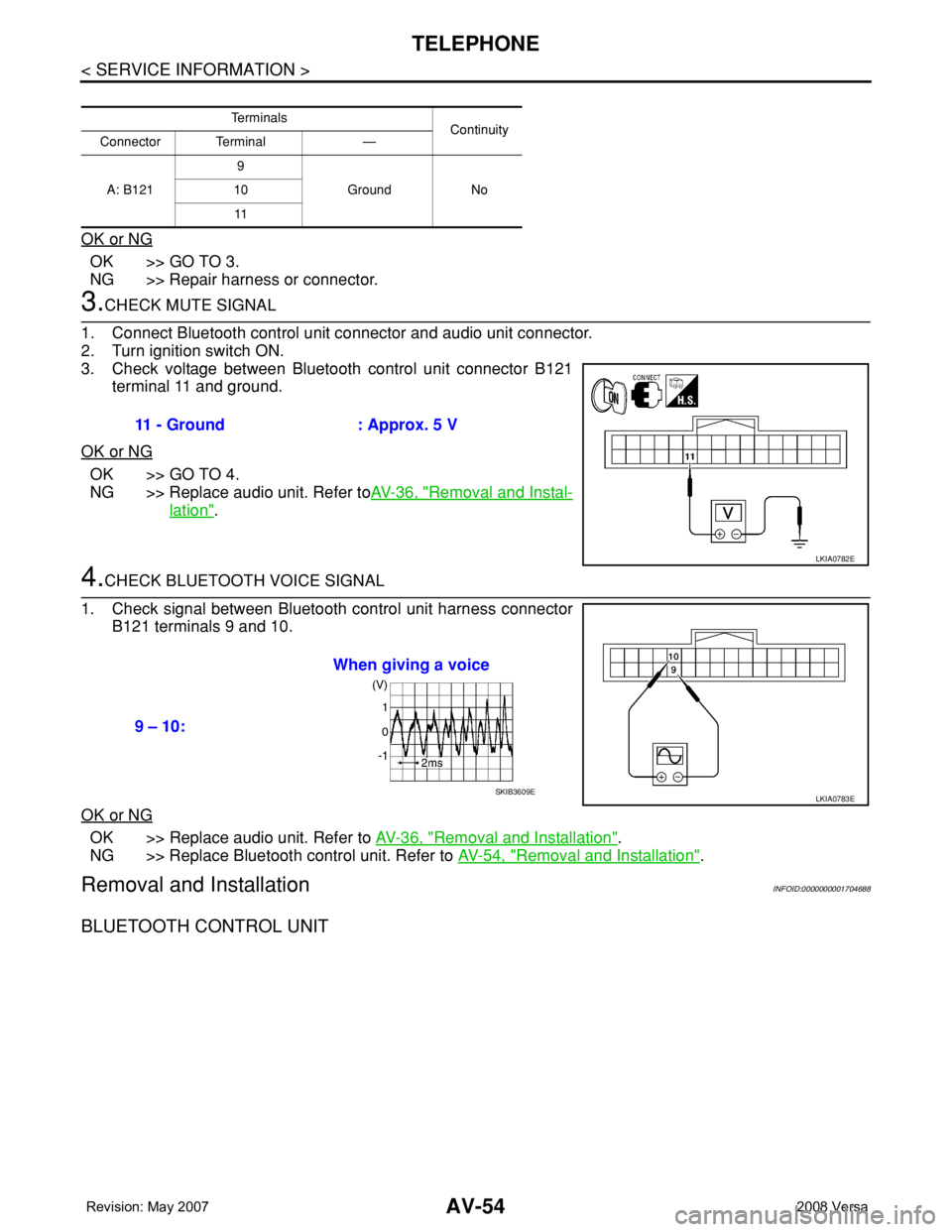
3.CHECK MUTE SIGNAL
1. Connect Bluetooth control unit connector and audio unit connector.
2. Turn ignition switch ON.
3. Check voltage between Bluetooth control unit connector B121
terminal 11 and ground.
OK or NG
OK >> GO TO 4.
NG >> Replace audio unit. Refer toAV-36, "
Removal and Instal-
lation".
4.CHECK BLUETOOTH VOICE SIGNAL
1. Check signal between Bluetooth control unit harness connector
B121 terminals 9 and 10.
OK or NG
OK >> Replace audio unit. Refer to AV-36, "Removal and Installation".
NG >> Replace Bluetooth control unit. Refer to AV-54, "
Removal and Installation".
Removal and InstallationINFOID:0000000001704688
BLUETOOTH CONTROL UNIT
Te r m i n a l s
Continuity
Connector Terminal —
A: B1219
Ground No 10
11
11 - Ground : Approx. 5 V
LKIA0782E
9 – 10:When giving a voice
LKIA0783ESKIB3609E