key NISSAN TIIDA 2008 Service Repair Manual
[x] Cancel search | Manufacturer: NISSAN, Model Year: 2008, Model line: TIIDA, Model: NISSAN TIIDA 2008Pages: 2771, PDF Size: 60.61 MB
Page 16 of 2771

AT-4
Diagnosis Procedure .............................................210
KEY INTERLOCK CABLE ...............................213
Removal and Installation .......................................213
ON-VEHICLE SERVICE ..................................216
Control Valve Assembly and Accumulators ...........216
Park/Neutral Position (PNP) Switch ......................219
Revolution Sensor .................................................221
Turbine Revolution Sensor (Power Train Revolu-
tion Sensor) ...........................................................
222
Differential Side Oil Seal ........................................223
AIR BREATHER HOSE ...................................225
Removal and Installation .......................................225
TRANSAXLE ASSEMBLY ..............................226
Removal and Installation .......................................226
OVERHAUL .....................................................230
Component ............................................................230
Oil Channel ............................................................237
Location of Adjusting Shims, Needle Bearings and
Thrust Washers .....................................................
238
Location of Snap Rings .........................................239
DISASSEMBLY ...............................................240
Disassembly ..........................................................240
REPAIR FOR COMPONENT PARTS ..............257
Manual Shaft .........................................................257
Oil Pump ................................................................260
Control Valve Assembly ........................................263
Control Valve Upper Body .....................................272
Control Valve Lower Body .....................................276
Reverse Clutch ......................................................279
High Clutch ............................................................284
Forward and Overrun Clutches .............................288
Low & Reverse Brake ............................................295
Rear Internal Gear and Forward Clutch Hub .........299
Output Shaft, Output Gear, Idler Gear, Reduction
Pinion Gear and Bearing Retainer .........................
302
Band Servo Piston Assembly ................................307
Final Drive .............................................................313
ASSEMBLY ......................................................318
Assembly (1) .........................................................318
Adjustment (1) .......................................................319
Assembly (2) .........................................................325
Adjustment (2) .......................................................330
Assembly (3) .........................................................333
SERVICE DATA AND SPECIFICATIONS
(SDS) ................................................................
341
General Specification ............................................341
Vehicle Speed at Which Gear Shifting Occurs .....341
Vehicle Speed at When Lock-up Occurs/Releases
.
341
Stall Speed ............................................................341
Line Pressure ........................................................341
Adjusting shims, Needle Bearings, Thrust Wash-
ers and Snap Rings ..............................................
341
Control Valves .......................................................343
Accumulator ..........................................................343
Clutches and Brakes .............................................343
Final Drive .............................................................345
Planetary Carrier ...................................................345
Oil Pump ...............................................................345
Input Shaft .............................................................345
Reduction Pinion Gear ..........................................345
Band Servo ...........................................................345
Output Shaft ..........................................................346
Bearing Retainer ...................................................346
Total End Play .......................................................346
Reverse Clutch End Play ......................................346
Removal and Installation .......................................346
Shift Solenoid Valves ............................................346
Solenoid Valves ....................................................346
A/T Fluid Temperature Sensor ..............................347
Revolution Sensor .................................................347
Dropping Resistor .................................................347
Turbine Revolution Sensor (Power Train Revolu-
tion Sensor) ...........................................................
347
Page 19 of 2771

PRECAUTIONS
AT-7
< SERVICE INFORMATION >
D
E
F
G
H
I
J
K
L
MA
B
AT
N
O
P
PRECAUTIONS
Precaution for Supplemental Restraint System (SRS) "AIR BAG" and "SEAT BELT
PRE-TENSIONER"
INFOID:0000000001703151
The Supplemental Restraint System such as “AIR BAG” and “SEAT BELT PRE-TENSIONER”, used along
with a front seat belt, helps to reduce the risk or severity of injury to the driver and front passenger for certain
types of collision. This system includes seat belt switch inputs and dual stage front air bag modules. The SRS
system uses the seat belt switches to determine the front air bag deployment, and may only deploy one front
air bag, depending on the severity of a collision and whether the front occupants are belted or unbelted.
Information necessary to service the system safely is included in the SRS and SB section of this Service Man-
ual.
WARNING:
• To avoid rendering the SRS inoperative, which could increase the risk of personal injury or death in
the event of a collision which would result in air bag inflation, all maintenance must be performed by
an authorized NISSAN/INFINITI dealer.
• Improper maintenance, including incorrect removal and installation of the SRS, can lead to personal
injury caused by unintentional activation of the system. For removal of Spiral Cable and Air Bag
Module, see the SRS section.
• Do not use electrical test equipment on any circuit related to the SRS unless instructed to in this
Service Manual. SRS wiring harnesses can be identified by yellow and/or orange harnesses or har-
ness connectors.
Precaution Necessary for Steering Wheel Rotation After Battery Disconnect
INFOID:0000000001703152
NOTE:
• This Procedure is applied only to models with Intelligent Key system and NVIS/IVIS (NISSAN/INFINITI
VEHICLE IMMOBILIZER SYSTEM - NATS).
• Remove and install all control units after disconnecting both battery cables with the ignition knob in the
″LOCK″ position.
• Always use CONSULT-III to perform self-diagnosis as a part of each function inspection after finishing work.
If DTC is detected, perform trouble diagnosis according to self-diagnostic results.
For models equipped with the Intelligent Key system and NVIS/IVIS, an electrically controlled steering lock
mechanism is adopted on the key cylinder.
For this reason, if the battery is disconnected or if the battery is discharged, the steering wheel will lock and
steering wheel rotation will become impossible.
If steering wheel rotation is required when battery power is interrupted, follow the procedure below before
starting the repair operation.
OPERATION PROCEDURE
1. Connect both battery cables.
NOTE:
Supply power using jumper cables if battery is discharged.
2. Use the Intelligent Key or mechanical key to turn the ignition switch to the ″ACC″ position. At this time, the
steering lock will be released.
3. Disconnect both battery cables. The steering lock will remain released and the steering wheel can be
rotated.
4. Perform the necessary repair operation.
5. When the repair work is completed, return the ignition switch to the ″LOCK″ position before connecting
the battery cables. (At this time, the steering lock mechanism will engage.)
6. Perform a self-diagnosis check of all control units using CONSULT-III.
Precaution for On Board Diagnosis (OBD) System of A/T and EngineINFOID:0000000001703153
The ECM has an on board diagnostic system. It will light up the malfunction indicator lamp (MIL) to warn the
driver of a malfunction causing emission deterioration.
CAUTION:
Page 54 of 2771
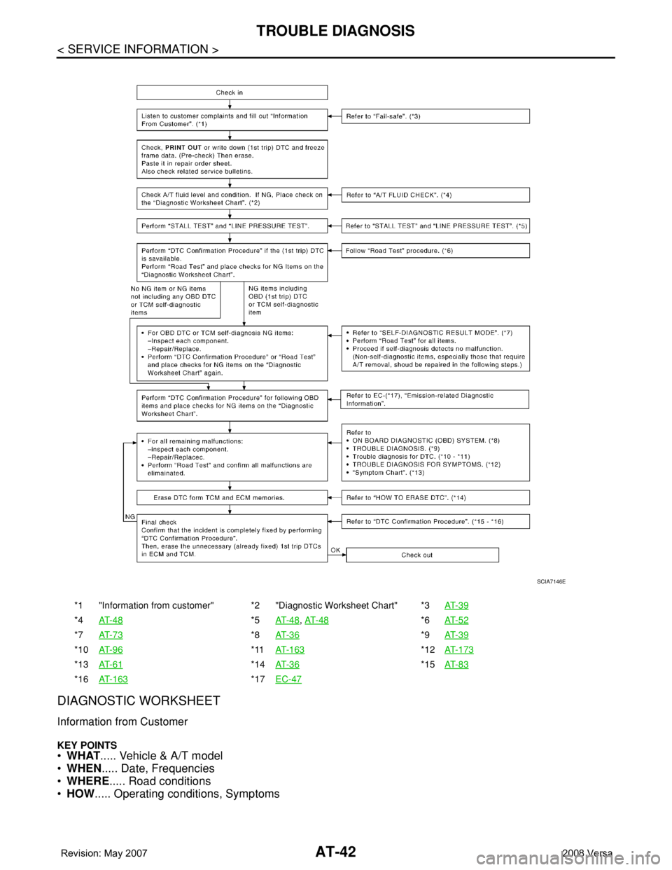
AT-42
< SERVICE INFORMATION >
TROUBLE DIAGNOSIS
DIAGNOSTIC WORKSHEET
Information from Customer
KEY POINTS
•WHAT..... Vehicle & A/T model
•WHEN..... Date, Frequencies
•WHERE..... Road conditions
•HOW..... Operating conditions, Symptoms
*1 "Information from customer" *2 "Diagnostic Worksheet Chart" *3AT- 3 9
*4AT- 4 8*5AT- 4 8, AT- 4 8*6AT- 5 2
*7AT- 7 3*8AT- 3 6*9AT- 3 9
*10AT- 9 6*11AT- 1 6 3*12AT- 1 7 3
*13AT- 6 1*14AT- 3 6*15AT- 8 3
*16AT- 1 6 3*17EC-47
SCIA7146E
Page 216 of 2771
AT-204
< SERVICE INFORMATION >
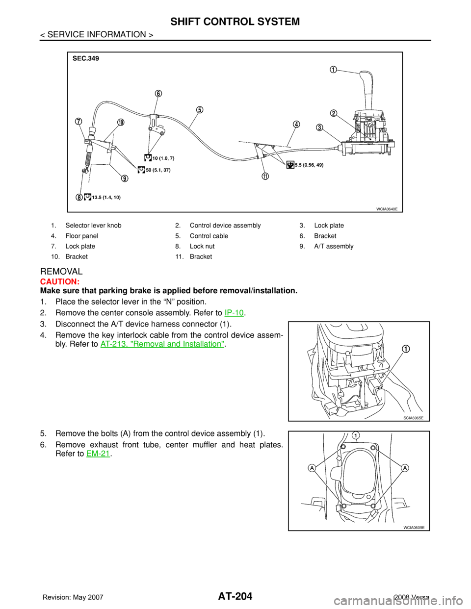
SHIFT CONTROL SYSTEM
REMOVAL
CAUTION:
Make sure that parking brake is applied before removal/installation.
1. Place the selector lever in the “N” position.
2. Remove the center console assembly. Refer to IP-10
.
3. Disconnect the A/T device harness connector (1).
4. Remove the key interlock cable from the control device assem-
bly. Refer to AT-213, "
Removal and Installation".
5. Remove the bolts (A) from the control device assembly (1).
6. Remove exhaust front tube, center muffler and heat plates.
Refer to EM-21
.
1. Selector lever knob 2. Control device assembly 3. Lock plate
4. Floor panel 5. Control cable 6. Bracket
7. Lock plate 8. Lock nut 9. A/T assembly
10. Bracket 11. Bracket
WCIA0640E
SCIA6965E
WCIA0609E
Page 221 of 2771
A/T SHIFT LOCK SYSTEM
AT-209
< SERVICE INFORMATION >
D
E
F
G
H
I
J
K
L
MA
B
AT
N
O
P
A/T SHIFT LOCK SYSTEM
DescriptionINFOID:0000000001703361
• The mechanical key interlock mechanism also operates as a shift lock:
With the ignition switch turned to ON, selector lever cannot be shifted from “P” position to any other position
unless brake pedal is depressed.
With the key removed, selector lever cannot be shifted from “P” position to any other position.
The key cannot be removed unless selector lever is placed in “P” position.
• The shift lock and key interlock mechanisms are controlled by the ON-OFF operation of the shift lock sole-
noid and by the operation of the rotator and slider located inside key cylinder, respectively.
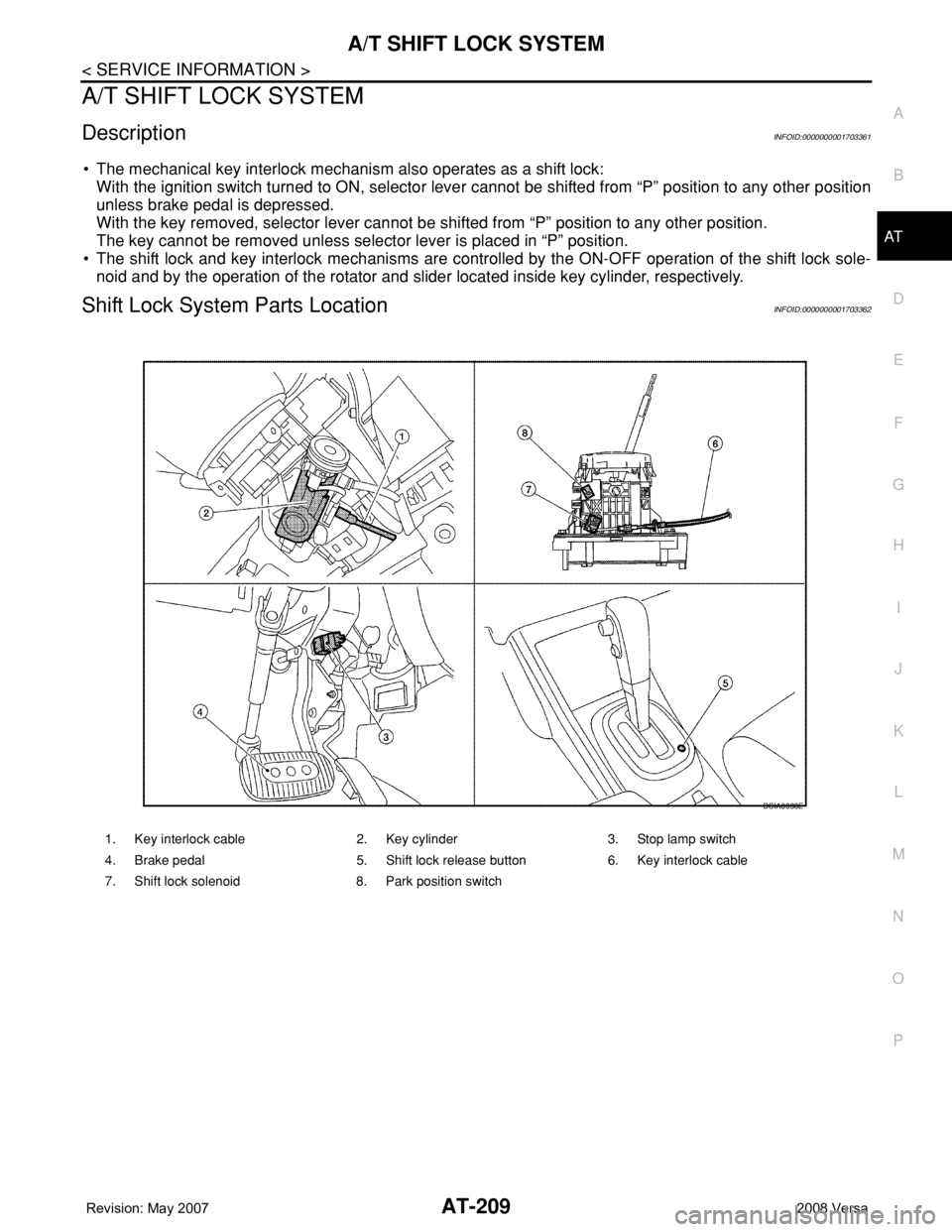
Shift Lock System Parts LocationINFOID:0000000001703362
1. Key interlock cable 2. Key cylinder 3. Stop lamp switch
4. Brake pedal 5. Shift lock release button 6. Key interlock cable
7. Shift lock solenoid 8. Park position switch
BCIA0038E
Page 223 of 2771
A/T SHIFT LOCK SYSTEM
AT-211
< SERVICE INFORMATION >
D
E
F
G
H
I
J
K
L
MA
B
AT
N
O
P
•Selector lever can be moved from “P” position with ignition key in ON position and brake pedal
released.
•Selector lever can be moved from “P” position when ignition switch is removed from key cylinder.
SYMPTOM 2:
•Ignition key cannot be removed when selector lever is set to “P” position.
•Ignition key can be removed when selector lever is set to any position except “P” position.
1.CHECK KEY INTERLOCK CABLE
Check key interlock cable for damage.
OK or NG
OK >> GO TO 2.
NG >> Repair key interlock cable. Refer to AT-213, "
Removal and Installation" .
2.CHECK A/T POSITION
Check A/T position. Refer to AT-207, "
Checking of A/T Position" .
OK or NG
OK >> GO TO 3.
NG >> Adjust control cable. Refer to AT-207, "
Adjustment of A/T Position" .
3.CHECK SHIFT LOCK SOLENOID AND PARK POSITION SWITCH
1. Turn ignition switch ON. (Do not start engine.)
2. Selector lever is set in “P” position.
3. Check operation sound.
OK or NG
OK >>INSPECTION END
NG >> GO TO 4.
4.CHECK POWER SOURCE
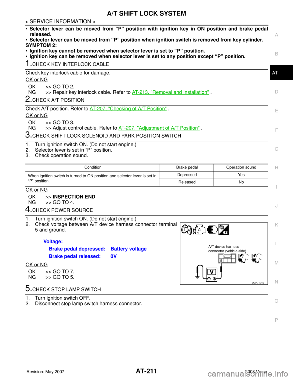
1. Turn ignition switch ON. (Do not start engine.)
2. Check voltage between A/T device harness connector terminal
5 and ground.
OK or NG
OK >> GO TO 7.
NG >> GO TO 5.
5.CHECK STOP LAMP SWITCH
1. Turn ignition switch OFF.
2. Disconnect stop lamp switch harness connector.
Condition Brake pedal Operation sound
When ignition switch is turned to ON position and selector lever is set in
“P” position.Depressed Yes
Released No
Voltage:
Brake pedal depressed: Battery voltage
Brake pedal released: 0V
SCIA7171E
Page 225 of 2771
KEY INTERLOCK CABLE
AT-213
< SERVICE INFORMATION >
D
E
F
G
H
I
J
K
L
MA
B
AT
N
O
P
KEY INTERLOCK CABLE
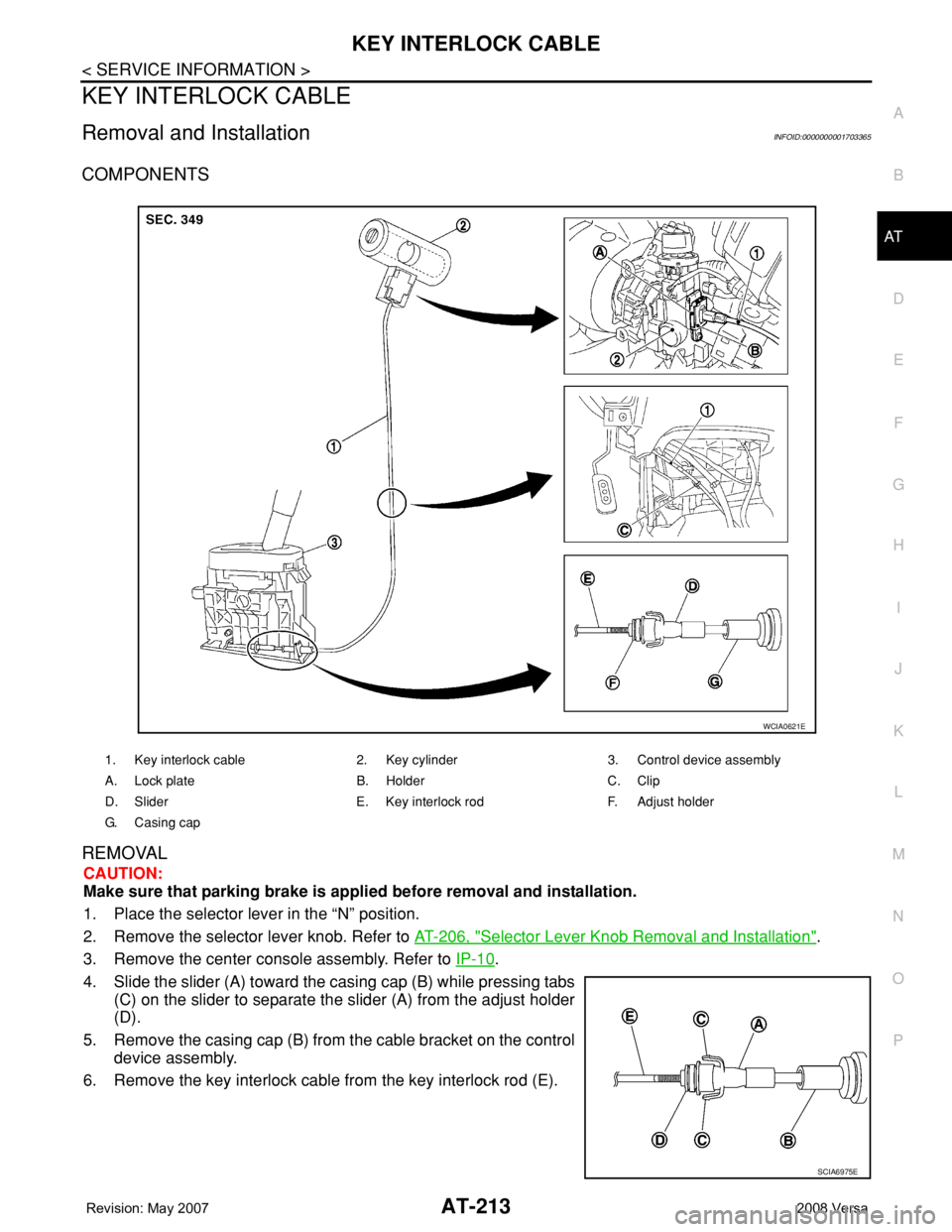
Removal and InstallationINFOID:0000000001703365
COMPONENTS
REMOVAL
CAUTION:
Make sure that parking brake is applied before removal and installation.
1. Place the selector lever in the “N” position.
2. Remove the selector lever knob. Refer to AT-206, "
Selector Lever Knob Removal and Installation".
3. Remove the center console assembly. Refer to IP-10
.
4. Slide the slider (A) toward the casing cap (B) while pressing tabs
(C) on the slider to separate the slider (A) from the adjust holder
(D).
5. Remove the casing cap (B) from the cable bracket on the control
device assembly.
6. Remove the key interlock cable from the key interlock rod (E).
1. Key interlock cable 2. Key cylinder 3. Control device assembly
A. Lock plate B. Holder C. Clip
D. Slider E. Key interlock rod F. Adjust holder
G. C a s i n g c a p
WCIA0621E
SCIA6975E
Page 226 of 2771
AT-214
< SERVICE INFORMATION >
KEY INTERLOCK CABLE
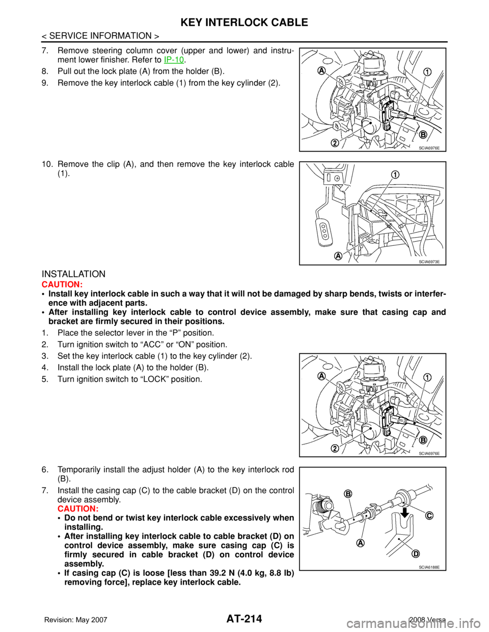
7. Remove steering column cover (upper and lower) and instru-
ment lower finisher. Refer to IP-10
.
8. Pull out the lock plate (A) from the holder (B).
9. Remove the key interlock cable (1) from the key cylinder (2).
10. Remove the clip (A), and then remove the key interlock cable
(1).
INSTALLATION
CAUTION:
• Install key interlock cable in such a way that it will not be damaged by sharp bends, twists or interfer-
ence with adjacent parts.
• After installing key interlock cable to control device assembly, make sure that casing cap and
bracket are firmly secured in their positions.
1. Place the selector lever in the “P” position.
2. Turn ignition switch to “ACC” or “ON” position.
3. Set the key interlock cable (1) to the key cylinder (2).
4. Install the lock plate (A) to the holder (B).
5. Turn ignition switch to “LOCK” position.
6. Temporarily install the adjust holder (A) to the key interlock rod
(B).
7. Install the casing cap (C) to the cable bracket (D) on the control
device assembly.
CAUTION:
• Do not bend or twist key interlock cable excessively when
installing.
• After installing key interlock cable to cable bracket (D) on
control device assembly, make sure casing cap (C) is
firmly secured in cable bracket (D) on control device
assembly.
• If casing cap (C) is loose [less than 39.2 N (4.0 kg, 8.8 lb)
removing force], replace key interlock cable.
SCIA6976E
SCIA6973E
SCIA6976E
SCIA6188E
Page 227 of 2771
KEY INTERLOCK CABLE
AT-215
< SERVICE INFORMATION >
D
E
F
G
H
I
J
K
L
MA
B
AT
N
O
P
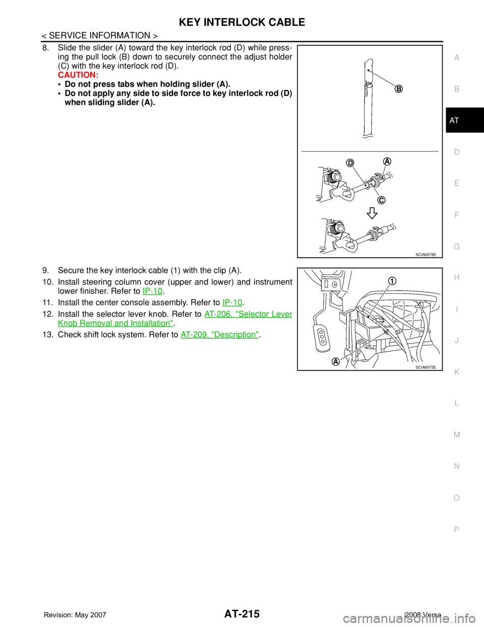
8. Slide the slider (A) toward the key interlock rod (D) while press-
ing the pull lock (B) down to securely connect the adjust holder
(C) with the key interlock rod (D).
CAUTION:
• Do not press tabs when holding slider (A).
• Do not apply any side to side force to key interlock rod (D)
when sliding slider (A).
9. Secure the key interlock cable (1) with the clip (A).
10. Install steering column cover (upper and lower) and instrument
lower finisher. Refer to IP-10
.
11. Install the center console assembly. Refer to IP-10
.
12. Install the selector lever knob. Refer to AT-206, "
Selector Lever
Knob Removal and Installation".
13. Check shift lock system. Refer to AT-209, "
Description".
SCIA6978E
SCIA6973E
Page 422 of 2771
BCS-6
< SERVICE INFORMATION >
BCM (BODY CONTROL MODULE)
• When CAN communication operation is detected, it switches to CAN communication status.
• When a state of the following switches changes, it switches to CAN communication state:
- Ignition switch
- Key switch (without Intelligent Key)
- Key switch and ignition knob switch (with Intelligent Key)
- Hazard switch
- Door lock/unlock switch
- Front door switch (LH, RH)
- Rear door switch (LH, RH)
- Back door lock assembly (Hatchback)
- Trunk key cylinder switch (Sedan)
- Trunk lamp switch and trunk release solenoid (Sedan)
- Combination switch (passing, lighting switch 1st position, front fog lamp)
- Keyfob (lock/unlock signal)
- Front door key cylinder switch LH
• When control performed only by BCM is required by switch, it shifts to CAN communication inactive
mode.
• Status of combination switch reading function is changed.
SYSTEMS CONTROLLED BY BCM DIRECTLY
• Power door lock system. Refer to BL-22 .
• Remote keyless entry system. Refer to BL-51
.
• Power window system. Refer to GW-18
. NOTE
• Sunroof system. Refer to RF-10. NOTE
• Room lamp timer. Refer to LT- 8 9 .
• Rear wiper and washer system. Refer to WW-24
.
NOTE:
Power supply only. No system control.
SYSTEMS CONTROLLED BY BCM AND IPDM E/R
• Panic system. Refer to BL-51 .
• Vehicle security (theft warning) system. Refer to BL-187
.
• NVIS(NATS) system. Refer to BL-210
.
• Headlamp, tail lamp and battery saver control systems. Refer to LT- 7 2
, LT- 4 or LT- 2 5 .
• Front fog lamp. Refer to LT- 3 9
.
• Front wiper and washer system. Refer to WW-3
.
• Rear window defogger system. Refer to GW-49
.
SYSTEMS CONTROLLED BY BCM AND COMBINATION METER
• Warning chime. Refer to DI-41 .
• Turn signal and hazard warning lamps. Refer to LT- 4 8
.
SYSTEMS CONTROLLED BY BCM AND INTELLIGENT KEY UNIT
• Intelligent Key system. Refer to BL-74 .
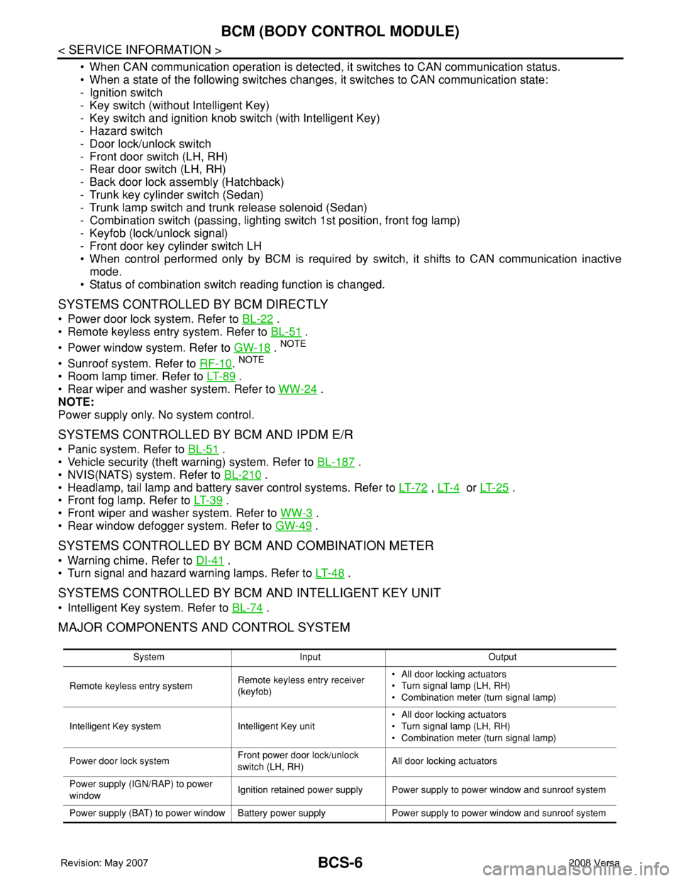
MAJOR COMPONENTS AND CONTROL SYSTEM
System Input Output
Remote keyless entry systemRemote keyless entry receiver
(keyfob)• All door locking actuators
• Turn signal lamp (LH, RH)
• Combination meter (turn signal lamp)
Intelligent Key system Intelligent Key unit• All door locking actuators
• Turn signal lamp (LH, RH)
• Combination meter (turn signal lamp)
Power door lock systemFront power door lock/unlock
switch (LH, RH)All door locking actuators
Power supply (IGN/RAP) to power
windowIgnition retained power supply Power supply to power window and sunroof system
Power supply (BAT) to power window Battery power supply Power supply to power window and sunroof system