Air NISSAN TIIDA 2008 Service Repair Manual
[x] Cancel search | Manufacturer: NISSAN, Model Year: 2008, Model line: TIIDA, Model: NISSAN TIIDA 2008Pages: 2771, PDF Size: 60.61 MB
Page 1 of 2771
-1
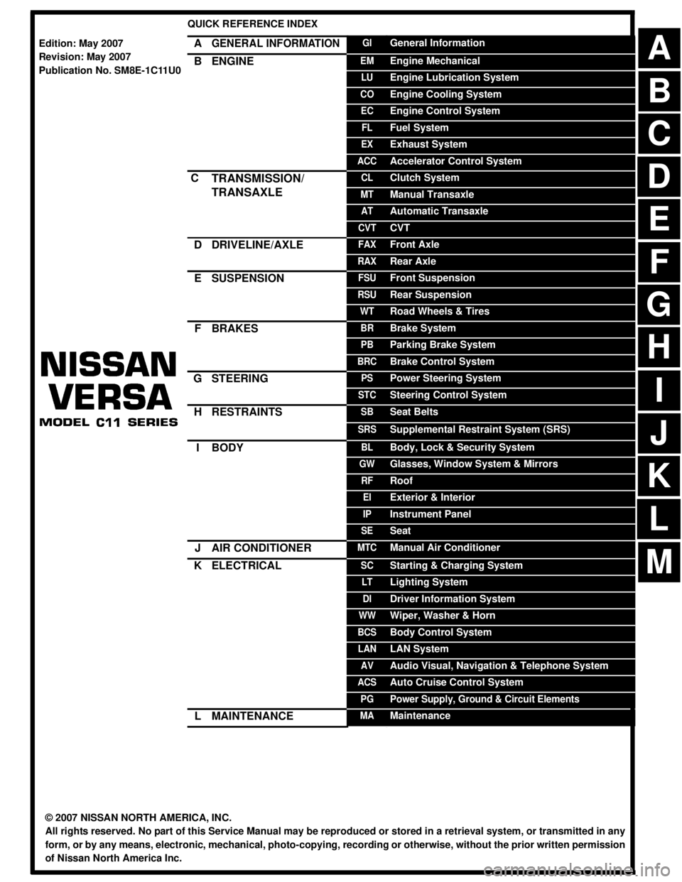
QUICK REFERENCE INDEX
AGENERAL INFORMATIONGIGeneral Information
BENGINEEMEngine Mechanical
LUEngine Lubrication System
COEngine Cooling System
ECEngine Control System
FLFuel System
EXExhaust System
ACCAccelerator Control System
CTRANSMISSION/
TRANSAXLECLClutch System
MTManual Transaxle
ATAutomatic Transaxle
CVTCVT
DDRIVELINE/AXLEFAXFront Axle
RAXRear Axle
ESUSPENSIONFSUFront Suspension
RSURear Suspension
WTRoad Wheels & Tires
FBRAKESBRBrake System
PBParking Brake System
BRCBrake Control System
GSTEERINGPSPower Steering System
STCSteering Control System
HRESTRAINTSSBSeat Belts
SRSSupplemental Restraint System (SRS)
IBODYBLBody, Lock & Security System
GWGlasses, Window System & Mirrors
RFRoof
EIExterior & Interior
IPInstrument Panel
SESeat
JAIR CONDITIONERMTCManual Air Conditioner
KELECTRICALSCStarting & Charging System
LTLighting System
DIDriver Information System
WWWiper, Washer & Horn
BCSBody Control System
LANLAN System
AVAudio Visual, Navigation & Telephone System
ACSAuto Cruise Control System
PGPower Supply, Ground & Circuit Elements
LMAINTENANCEMAMaintenance
Edition: May 2007
Revision: May 2007
Publication No. SM8E-1C11U0
B
D
© 2007 NISSAN NORTH AMERICA, INC.
All rights reserved. No part of this Service Manual may be reproduced or stored in a retrieval system, or transmitted in any
form, or by any means, electronic, mechanical, photo-copying, recording or otherwise, without the prior written permission
of Nissan North America Inc.
A
C
E
F
G
H
I
J
K
L
M
Page 2 of 2771
-2
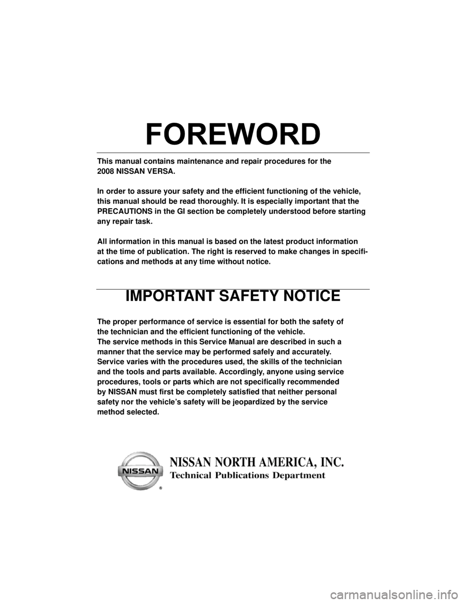
This manual contains maintenance and repair procedures for the
2008 NISSAN VERSA.
In order to assure your safety and the efficient functioning of the vehicle,
this manual should be read thoroughly. It is especially important that the
PRECAUTIONS in the GI section be completely understood before starting
any repair task.
All information in this manual is based on the latest product information
at the time of publication. The right is reserved to make changes in specifi-
cations and methods at any time without notice.
IMPORTANT SAFETY NOTICE
The proper performance of service is essential for both the safety of
the technician and the efficient functioning of the vehicle.
The service methods in this Service Manual are described in such a
manner that the service may be performed safely and accurately.
Service varies with the procedures used, the skills of the technician
and the tools and parts available. Accordingly, anyone using service
procedures, tools or parts which are not specifically recommended
by NISSAN must first be completely satisfied that neither personal
safety nor the vehicle’s safety will be jeopardized by the service
method selected.
Page 3 of 2771

PLEASEHELPMAKETHISSERVICEMANUALBETTER!
YourcommentsareimportanttoNISSANandwillhelpustoimproveourServiceManuals.
UsethisformtoreportanyissuesorcommentsyoumayhaveregardingourServiceManuals.
Pleaseprintthisformandtypeorwriteyourcommentsbelow.Mailorfaxto:
NissanNorthAmerica,Inc.
TechnicalServiceInformation
39001SunriseDrive,P.O.Box9200
FarmingtonHills,MIUSA48331
FAX:(248)488-3910
SERVICEMANUAL:Model:Year:
PUBLICATIONNO.(Refer to Quick Reference Index ):
Pleasedescribeany Service Manualissuesorproblemsindetail:
Pagenumber(s)Note:Pleaseincludeacopyofeachpage,markedwithyourcomments.
Arethetroublediagnosisprocedureslogicalandeasytouse?(circleyouranswer)YESNO
Ifno,whatpagenumber(s)?Note:Pleaseincludeacopyofeachpage,markedwithyourcomments.
Pleasedescribetheissueorproblemindetail:
Istheorganizationofthemanualclearandeasytofollow?(circleyouranswer)YESNO
Pleasecomment:
WhatinformationshouldbeincludedinNISSANServiceManualstobettersupportyouinservicingor
repairingcustomervehicles?
DATE:YOURNAME:POSITION:
DEALER:DEALERNO.:ADDRESS:
CITY:STATE/PROV./COUNTRY:ZIP/POSTALCODE:
Page 6 of 2771

2008
QUICK REFERENCE CHART: VERSA
*: Fuel, engine coolant and engine oil full. Spare tire, jack, hand tools and mats in designated positions.
General SpecificationINFOID:0000000001903532
Brake PedalINFOID:0000000001903533
Unit: mm (in)
Front Disc BrakeINFOID:0000000001903534
Unit: mm (in)
Rear Drum BrakeINFOID:0000000001903535
Unit: mm (in)
Front brake Brake model CLZ25VACylinder bore diameter 57.2 mm (2.252 in)
Pad
Length × width × thickness 125.6 mm
× 46.0 mm × 9.5 mm
(4.945 in × 1.811 in × 0.374 in)
Rotor outer diameter × thickness 280 mm × 24.0 mm (11.02 in × 0.945 in)
Rear brake Brake model LT20D Cylinder bore diameter 15.87 mm (0.625 in)
Lining
Length × width × thickness 194.1 mm
× 30.0 mm × 4.0 mm
(7.642 in × 1.181 in × 0.157 in)
Drum outer diameter 228.6 mm (9.000 in)
Master cylinder Cylinder bore diameter 22.22 mm (0.875 in)
Control valve Valve model Electric brake force distribution
Brake booster Booster model C255 Diaphragm diameter 255 mm (10.04 in)
Brake pedal free height (from dash panel top surface) A/T, CVT model 172.4 - 182.4 (6.79 - 7.18)
M/T model 162.3 - 172.3 (6.39 - 6.78)
Brake pedal depressed height
[under a force of 490 N (50 kg-f, 110 lb-f) with the engine running] A/T, CVT model 98 (3.86) or more
M/T model 90 (3.54) or more
Clearance between brake pedal lever and the threaded end of stop lamp switch 0.74 - 1.96 (0.0291 - 0.0772)
Pedal play 3 - 11 (0.12 - 0.43)
Brake modelCLZ25VA
Brake pad Standard thickness (new) 9.5 (0.374)
Repair limit thickness 2.0 (0.079)
Disc rotor Standard thickness (new) 24.0 (0.945)
Repair limit thickness 22.0 (0.866)
Runout limit 0.04 (0.0016)
Maximum uneven wear (mea-
sured at 8 positions)
0.02 mm (0.0008 in) or less
Brake model
LT 2 0 D
Brake lining Standard thickness (new) 4.0 (0.157)
Repair limit thickness 1.5 (0.059)
Drum Standard inner diameter (new) 228.6 (9.000)
Repair limit inner diameter 230.0 (9.055)
Page 7 of 2771

QUICK REFERENCE CHART: VERSA
2008
Fluids and LubricantsINFOID:0000000001903536
DescriptionCapacity (Approximate)
Liter US measure Imp measure
Fuel 52.0 13 3/4 gal 11 1/2 gal
Engine oil
Drain and refill With oil filter change 3.9 4 1/8 qt 3 3/8 qt
Without oil filter change 3.7 3 7/8 qt 3 1/4 qt
Dry engine (engine overhaul) 4.9 5 1/8 qt 4 3/8 qt
Cooling system
(with reservoir at max level) 6.8 7 1/4 qt 6 qt
Manual transaxle fluid (MTF) 2.0 4 1/4 pt 3 1/2 pt
Automatic transaxle fluid (ATF) 7.9 8 3/8 qt 7 qt
CVT fluid 8.3 8 3/4 qt 7 1/4 qt
Brake and clutch fluid — — —
Multi-purpose grease — — —
Windshield washer fluid 4.5 4 3/4 qt 4 qt
Air conditioning system refrigerant 0.45 ± 0.05 kg 0.99 ± 0.11 lb 0.99 ± 0.11 lb
Air conditioning system oil Typ e 1
120 m4.1 fl oz 4.2 fl oz
Typ e 2 100 m3.4 fl oz 3.5 fl oz
Page 8 of 2771

ACC-1
ENGINE
C
D
E
F
G
H
I
J
K
L
M
SECTION ACC
A
ACC
N
O
P
CONTENTS
ACCELERATOR CONTROL SYSTEM
SERVICE INFORMATION ............................2
PRECAUTIONS ...................................................2
Precaution for Supplemental Restraint System
(SRS) "AIR BAG" and "SEAT BELT PRE-TEN-
SIONER" ...................................................................
2
ACCELERATOR CONTROL SYSTEM ..............3
Component ...............................................................3
Removal and Installation ..........................................3
Page 9 of 2771

ACC-2
< SERVICE INFORMATION >
PRECAUTIONS
SERVICE INFORMATION
PRECAUTIONS
Precaution for Supplemental Restraint System (SRS) "AIR BAG" and "SEAT BELT
PRE-TENSIONER"
INFOID:0000000001703109
The Supplemental Restraint System such as “AIR BAG” and “SEAT BELT PRE-TENSIONER”, used along
with a front seat belt, helps to reduce the risk or severity of injury to the driver and front passenger for certain
types of collision. This system includes seat belt switch inputs and dual stage front air bag modules. The SRS
system uses the seat belt switches to determine the front air bag deployment, and may only deploy one front
air bag, depending on the severity of a collision and whether the front occupants are belted or unbelted.
Information necessary to service the system safely is included in the SR and SB section of this Service Man-
ual.
WARNING:
• To avoid rendering the SRS inoperative, which could increase the risk of personal injury or death in
the event of a collision which would result in air bag inflation, all maintenance must be performed by
an authorized NISSAN/INFINITI dealer.
• Improper maintenance, including incorrect removal and installation of the SRS, can lead to personal
injury caused by unintentional activation of the system. For removal of Spiral Cable and Air Bag
Module, see the SR section.
• Do not use electrical test equipment on any circuit related to the SRS unless instructed to in this
Service Manual. SRS wiring harnesses can be identified by yellow and/or orange harnesses or har-
ness connectors.
Page 13 of 2771

AT-1
TRANSMISSION/TRANSAXLE
D
E
F
G
H
I
J
K
L
M
SECTION AT
A
B
AT
N
O
P
CONTENTS
AUTOMATIC TRANSAXLE
SERVICE INFORMATION ............................5
INDEX FOR DTC .................................................5
Alphabetical Index .....................................................5
DTC No. Index ..........................................................5
PRECAUTIONS ...................................................7
Precaution for Supplemental Restraint System
(SRS) "AIR BAG" and "SEAT BELT PRE-TEN-
SIONER" ...................................................................
7
Precaution Necessary for Steering Wheel Rota-
tion After Battery Disconnect .....................................
7
Precaution for On Board Diagnosis (OBD) System
of A/T and Engine .....................................................
7
Precaution .................................................................8
Service Notice or Precaution .....................................9
PREPARATION ..................................................10
Special Service Tool ...............................................10
Commercial Service Tool ........................................13
A/T FLUID ...........................................................15
Checking A/T Fluid ..................................................15
Changing A/T Fluid .................................................15
A/T Fluid Cooler Cleaning .......................................16
A/T CONTROL SYSTEM ....................................19
Cross-Sectional View ..............................................19
Shift Mechanism ......................................................19
TCM Function ..........................................................27
CAN Communication ...............................................28
Input/Output Signal of TCM .....................................28
Line Pressure Control .............................................29
Shift Control ............................................................30
Lock-up Control .......................................................31
Engine Brake Control (Overrun Clutch Control) ......32
Control Valve ...........................................................34
Centrifugal Cancel Mechanism ...............................34
ON BOARD DIAGNOSTIC (OBD) SYSTEM ......36
Introduction .............................................................36
OBD-II Function for A/T System ..............................36
One or Two Trip Detection Logic of OBD-II .............36
OBD-II Diagnostic Trouble Code (DTC) ..................36
Malfunction Indicator Lamp (MIL) ............................38
TROUBLE DIAGNOSIS ....................................39
DTC Inspection Priority Chart ..................................39
Fail-Safe ..................................................................39
How to Perform Trouble Diagnosis for Quick and
Accurate Repair .......................................................
40
A/T Electrical Parts Location ...................................46
Circuit Diagram ........................................................47
Inspections Before Trouble Diagnosis .....................48
Road Test ................................................................52
Check Before Engine Is Started ..............................53
Check at Idle ............................................................53
Cruise Test - Part 1 .................................................55
Cruise Test - Part 2 .................................................58
Cruise Test - Part 3 .................................................59
Vehicle Speed at Which Gear Shifting Occurs ........61
Vehicle Speed at Which Lock-up Occurs/Releas-
es .............................................................................
61
Symptom Chart ........................................................61
TCM Terminal and Reference Value .......................71
CONSULT-III Function (A/T) ...................................73
Diagnosis Procedure without CONSULT-III ............78
DTC U1000 CAN COMMUNICATION LINE .....83
Description ...............................................................83
On Board Diagnosis Logic .......................................83
Possible Cause ........................................................83
DTC Confirmation Procedure ..................................83
Wiring Diagram - AT - CAN .....................................84
Diagnosis Procedure ...............................................85
DTC P0705 PARK/NEUTRAL POSITION
(PNP) SWITCH ..................................................
86
Description ...............................................................86
CONSULT-III Reference Value in Data Monitor
Mode ........................................................................
86
On Board Diagnosis Logic .......................................86
Possible Cause ........................................................86
Page 16 of 2771

AT-4
Diagnosis Procedure .............................................210
KEY INTERLOCK CABLE ...............................213
Removal and Installation .......................................213
ON-VEHICLE SERVICE ..................................216
Control Valve Assembly and Accumulators ...........216
Park/Neutral Position (PNP) Switch ......................219
Revolution Sensor .................................................221
Turbine Revolution Sensor (Power Train Revolu-
tion Sensor) ...........................................................
222
Differential Side Oil Seal ........................................223
AIR BREATHER HOSE ...................................225
Removal and Installation .......................................225
TRANSAXLE ASSEMBLY ..............................226
Removal and Installation .......................................226
OVERHAUL .....................................................230
Component ............................................................230
Oil Channel ............................................................237
Location of Adjusting Shims, Needle Bearings and
Thrust Washers .....................................................
238
Location of Snap Rings .........................................239
DISASSEMBLY ...............................................240
Disassembly ..........................................................240
REPAIR FOR COMPONENT PARTS ..............257
Manual Shaft .........................................................257
Oil Pump ................................................................260
Control Valve Assembly ........................................263
Control Valve Upper Body .....................................272
Control Valve Lower Body .....................................276
Reverse Clutch ......................................................279
High Clutch ............................................................284
Forward and Overrun Clutches .............................288
Low & Reverse Brake ............................................295
Rear Internal Gear and Forward Clutch Hub .........299
Output Shaft, Output Gear, Idler Gear, Reduction
Pinion Gear and Bearing Retainer .........................
302
Band Servo Piston Assembly ................................307
Final Drive .............................................................313
ASSEMBLY ......................................................318
Assembly (1) .........................................................318
Adjustment (1) .......................................................319
Assembly (2) .........................................................325
Adjustment (2) .......................................................330
Assembly (3) .........................................................333
SERVICE DATA AND SPECIFICATIONS
(SDS) ................................................................
341
General Specification ............................................341
Vehicle Speed at Which Gear Shifting Occurs .....341
Vehicle Speed at When Lock-up Occurs/Releases
.
341
Stall Speed ............................................................341
Line Pressure ........................................................341
Adjusting shims, Needle Bearings, Thrust Wash-
ers and Snap Rings ..............................................
341
Control Valves .......................................................343
Accumulator ..........................................................343
Clutches and Brakes .............................................343
Final Drive .............................................................345
Planetary Carrier ...................................................345
Oil Pump ...............................................................345
Input Shaft .............................................................345
Reduction Pinion Gear ..........................................345
Band Servo ...........................................................345
Output Shaft ..........................................................346
Bearing Retainer ...................................................346
Total End Play .......................................................346
Reverse Clutch End Play ......................................346
Removal and Installation .......................................346
Shift Solenoid Valves ............................................346
Solenoid Valves ....................................................346
A/T Fluid Temperature Sensor ..............................347
Revolution Sensor .................................................347
Dropping Resistor .................................................347
Turbine Revolution Sensor (Power Train Revolu-
tion Sensor) ...........................................................
347
Page 19 of 2771

PRECAUTIONS
AT-7
< SERVICE INFORMATION >
D
E
F
G
H
I
J
K
L
MA
B
AT
N
O
P
PRECAUTIONS
Precaution for Supplemental Restraint System (SRS) "AIR BAG" and "SEAT BELT
PRE-TENSIONER"
INFOID:0000000001703151
The Supplemental Restraint System such as “AIR BAG” and “SEAT BELT PRE-TENSIONER”, used along
with a front seat belt, helps to reduce the risk or severity of injury to the driver and front passenger for certain
types of collision. This system includes seat belt switch inputs and dual stage front air bag modules. The SRS
system uses the seat belt switches to determine the front air bag deployment, and may only deploy one front
air bag, depending on the severity of a collision and whether the front occupants are belted or unbelted.
Information necessary to service the system safely is included in the SRS and SB section of this Service Man-
ual.
WARNING:
• To avoid rendering the SRS inoperative, which could increase the risk of personal injury or death in
the event of a collision which would result in air bag inflation, all maintenance must be performed by
an authorized NISSAN/INFINITI dealer.
• Improper maintenance, including incorrect removal and installation of the SRS, can lead to personal
injury caused by unintentional activation of the system. For removal of Spiral Cable and Air Bag
Module, see the SRS section.
• Do not use electrical test equipment on any circuit related to the SRS unless instructed to in this
Service Manual. SRS wiring harnesses can be identified by yellow and/or orange harnesses or har-
ness connectors.
Precaution Necessary for Steering Wheel Rotation After Battery Disconnect
INFOID:0000000001703152
NOTE:
• This Procedure is applied only to models with Intelligent Key system and NVIS/IVIS (NISSAN/INFINITI
VEHICLE IMMOBILIZER SYSTEM - NATS).
• Remove and install all control units after disconnecting both battery cables with the ignition knob in the
″LOCK″ position.
• Always use CONSULT-III to perform self-diagnosis as a part of each function inspection after finishing work.
If DTC is detected, perform trouble diagnosis according to self-diagnostic results.
For models equipped with the Intelligent Key system and NVIS/IVIS, an electrically controlled steering lock
mechanism is adopted on the key cylinder.
For this reason, if the battery is disconnected or if the battery is discharged, the steering wheel will lock and
steering wheel rotation will become impossible.
If steering wheel rotation is required when battery power is interrupted, follow the procedure below before
starting the repair operation.
OPERATION PROCEDURE
1. Connect both battery cables.
NOTE:
Supply power using jumper cables if battery is discharged.
2. Use the Intelligent Key or mechanical key to turn the ignition switch to the ″ACC″ position. At this time, the
steering lock will be released.
3. Disconnect both battery cables. The steering lock will remain released and the steering wheel can be
rotated.
4. Perform the necessary repair operation.
5. When the repair work is completed, return the ignition switch to the ″LOCK″ position before connecting
the battery cables. (At this time, the steering lock mechanism will engage.)
6. Perform a self-diagnosis check of all control units using CONSULT-III.
Precaution for On Board Diagnosis (OBD) System of A/T and EngineINFOID:0000000001703153
The ECM has an on board diagnostic system. It will light up the malfunction indicator lamp (MIL) to warn the
driver of a malfunction causing emission deterioration.
CAUTION: