change wheel NISSAN TIIDA 2008 Service Repair Manual
[x] Cancel search | Manufacturer: NISSAN, Model Year: 2008, Model line: TIIDA, Model: NISSAN TIIDA 2008Pages: 2771, PDF Size: 60.61 MB
Page 364 of 2771

AUDIO
AV-5
< SERVICE INFORMATION >
C
D
E
F
G
H
I
J
L
MA
B
AV
N
O
P
• to audio unit terminal 21 (with premium system)
• through body grounds M57 and M61 and
• to subwoofer terminal 3 (with premium system)
• through body grounds B7 and B19.
Then audio signals are supplied
• through audio unit terminals 2, 3, 4, 5, 11, 12, 13, and 14
• to terminals + and - of front door speaker LH and RH and
• to terminals + and - of tweeter LH and RH and
• to terminals + and - of rear door speaker LH and RH and
• to terminals 2 and 6 of subwoofer (with premium system).
Steering Wheel Audio Control Switches (with Bluetooth)
When one of steering wheel audio control switches is pushed, the resistance in steering switch circuit changes
depending on which button is pushed.
Satellite Radio Tuner (Pre-wiring)
The satellite radio tuner pre-wiring allows connection of a satellite radio tuner.
Power is supplied at all times
• through 20A fuse (No. 27, located in the fuse and fusible link box)
• to satellite radio tuner pre-wiring terminal 32.
With the ignition switch in the ACC or ON position, power is supplied
• through 10A fuse (No. 20, located in the fuse and fusible link box)
• to satellite radio tuner pre-wiring terminal 36.
Then audio signals are supplied
• through satellite radio tuner pre-wiring terminals 21, 22, 23 and 24
• to audio unit terminals 41, 42, 43 and 44.
Satellite Radio Tuner (Factory Installed)
Power is supplied at all times
• through 20A fuse (No. 27, located in the fuse and fusible link box)
• to satellite radio tuner terminal 32.
With the ignition switch in the ACC or ON position, power is supplied
• through 10A fuse (No. 20, located in the fuse and fusible link box)
• to satellite radio tuner terminal 36.
Ground is supplied through the case of the satellite radio tuner.
Then audio signals are supplied
• through satellite radio tuner terminals 21, 22, 23 and 24
• to audio unit terminals 41, 42, 43 and 44.
Ground is supplied through the case of the satellite radio tuner.
SPEED SENSITIVE VOLUME SYSTEM (MID LEVEL AND PREMIUM SYSTEM)
Volume level of this system goes up and down automatically in proportion to the vehicle speed. The control
level can be selected by the customer. Refer to Owner's Manual for operating instructions.
Page 403 of 2771
AV-44
< SERVICE INFORMATION >
TELEPHONE
tooth cellular telephones may not be recognized by the Bluetooth control unit. When a cellular telephone or
the Bluetooth control unit is replaced, the telephone must be paired with the Bluetooth control unit. Different
cellular telephones may have different pairing procedures. Refer to the cellular telephone operating manual.
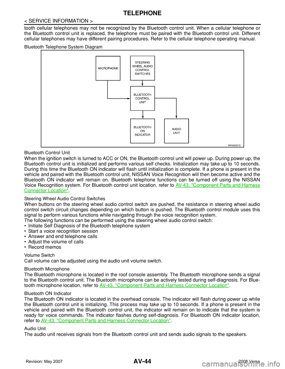
Bluetooth Telephone System Diagram
Bluetooth Control Unit
When the ignition switch is turned to ACC or ON, the Bluetooth control unit will power up. During power up, the
Bluetooth control unit is initialized and performs various self checks. Initialization may take up to 10 seconds.
During this time the Bluetooth ON indicator will flash until initialization is complete. If a phone is present in the
vehicle and paired with the Bluetooth control unit, NISSAN Voice Recognition will then become active and the
Bluetooth ON indicator will remain on. Bluetooth telephone functions can be turned off using the NISSAN
Voice Recognition system. For Bluetooth control unit location, refer to AV-43, "
Component Parts and Harness
Connector Location".
Steering Wheel Audio Control Switches
When buttons on the steering wheel audio control switch are pushed, the resistance in steering wheel audio
control switch circuit changes depending on which button is pushed. The Bluetooth control module uses this
signal to perform various functions while navigating through the voice recognition system.
The following functions can be performed using the steering wheel audio control switch:
• Initiate Self Diagnosis of the Bluetooth telephone system
• Start a voice recognition session
• Answer and end telephone calls
• Adjust the volume of calls
• Record memos
Volume Switch
Call volume can be adjusted using the audio unit volume switch.
Bluetooth Microphone
The Bluetooth microphone is located in the roof console assembly. The Bluetooth microphone sends a signal
to the Bluetooth control unit. The Bluetooth microphone can be actively tested during self-diagnosis. For Blue-
tooth microphone location, refer to AV-43, "
Component Parts and Harness Connector Location".
Bluetooth ON Indicator
The Bluetooth ON indicator is located in the overhead console. The indicator will flash during power up while
the Bluetooth control unit is initializing. This process may take up to 10 seconds. If a phone is present in the
vehicle and paired with the Bluetooth control unit, the indicator will remain on to indicate that the system is
ready for voice commands. The indicator flashes during self-diagnosis. For Bluetooth ON indicator location,
refer to AV-43, "
Component Parts and Harness Connector Location".
Audio Unit
The audio unit receives signals from the Bluetooth control unit and sends audio signals to the speakers.
WKIA6001E
Page 510 of 2771
BL-76
< SERVICE INFORMATION >
INTELLIGENT KEY SYSTEM
System Description
INFOID:0000000001703999
• The Intelligent Key system is a system that makes it possible to lock and unlock the door locks (door lock/
unlock function), and start the engine (engine start function) by carrying around the Intelligent Key (without
some key operation), which operates based on the results of electronic ID verification using two-way com-
munications between the Intelligent Key and the vehicle (Intelligent Key unit).
• Vehicles equipped with a manual transmission include a key interlock solenoid located in the steering col-
umn to prevent accidental shut-off of the ignition switch and locking of the steering wheel during driving con-
dition when the vehicle is moving.
CAUTION:
The driver should always carry the Intelligent Key
• Operation of the remote controller buttons on the Intelligent Key also provides the same functions as the
remote control entry system. (Remote keyless entry functions)
• If an action that does not meet the operating conditions of the Intelligent Key system is taken, the buzzer
goes off to inform the driver. (Warning chime functions)
• When a door lock is locked or unlocked with request switch or remote controller button operation, the hazard
lamps flash and the buzzer (outside vehicle) sounds (Hazard and buzzer reminder function).
• Even if the Intelligent Key battery is completely discharged, the door locks can be locked and unlocked and
the engine started with the mechanical key built into the Intelligent Key.
• The settings for each function can be changed with the CONSULT-III.
• If an Intelligent Key is lost, a new Intelligent Key can be registered. A maximum of 4 Intelligent Keys can be
registered.
• It has been made possible to diagnose the system and register an Intelligent Key with the CONSULT-III.
DOOR LOCK/UNLOCK FUNCTION
Only when pressing the request switch, it is possible to lock and unlock the door by carrying around the Intelli-
gent Key (without some key operation).
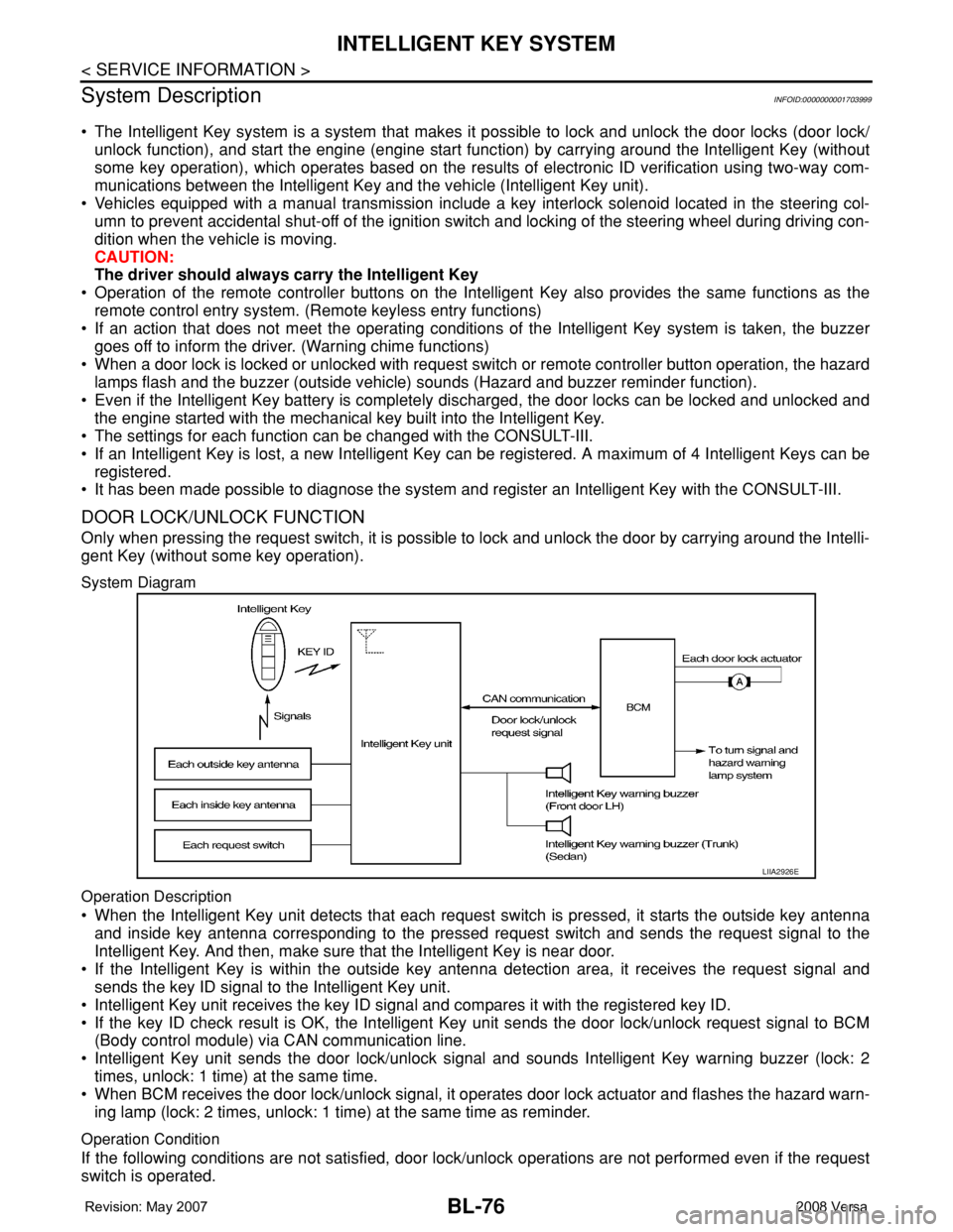
System Diagram
Operation Description
• When the Intelligent Key unit detects that each request switch is pressed, it starts the outside key antenna
and inside key antenna corresponding to the pressed request switch and sends the request signal to the
Intelligent Key. And then, make sure that the Intelligent Key is near door.
• If the Intelligent Key is within the outside key antenna detection area, it receives the request signal and
sends the key ID signal to the Intelligent Key unit.
• Intelligent Key unit receives the key ID signal and compares it with the registered key ID.
• If the key ID check result is OK, the Intelligent Key unit sends the door lock/unlock request signal to BCM
(Body control module) via CAN communication line.
• Intelligent Key unit sends the door lock/unlock signal and sounds Intelligent Key warning buzzer (lock: 2
times, unlock: 1 time) at the same time.
• When BCM receives the door lock/unlock signal, it operates door lock actuator and flashes the hazard warn-
ing lamp (lock: 2 times, unlock: 1 time) at the same time as reminder.
Operation Condition
If the following conditions are not satisfied, door lock/unlock operations are not performed even if the request
switch is operated.
LIIA2926E
Page 758 of 2771
FRONT DISC BRAKE
BR-27
< SERVICE INFORMATION >
C
D
E
G
H
I
J
K
L
MA
B
BR
N
O
P
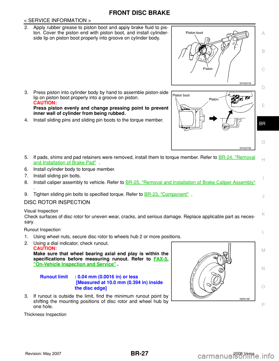
2. Apply rubber grease to piston boot and apply brake fluid to pis-
ton. Cover the piston end with piston boot, and install cylinder-
side lip on piston boot properly into groove on cylinder body.
3. Press piston into cylinder body by hand to assemble piston-side
lip on piston boot properly into a groove on piston.
CAUTION:
Press piston evenly and change pressing point to prevent
inner wall of cylinder from being rubbed.
4. Install sliding pins and sliding pin boots to the torque member.
5. If pads, shims and pad retainers were removed, install them to torque member. Refer to BR-24, "
Removal
and Installation of Brake Pad" .
6. Install cylinder body to torque member.
7. Install sliding pin bolts.
8. Install caliper assembly to vehicle. Refer to BR-25, "
Removal and Installation of Brake Caliper Assembly"
.
9. Tighten sliding pin bolts to specified torque. Refer to BR-23, "
Component" .
DISC ROTOR INSPECTION
Visual Inspection
Check surfaces of disc rotor for uneven wear, cracks, and serious damage. Replace applicable part as neces-
sary.
Runout Inspection
1. Using wheel nuts, secure disc rotor to wheels hub 2 or more positions.
2. Using a dial indicator, check runout.
CAUTION:
Make sure that wheel bearing axial end play is within the
specifications before measuring runout. Refer to FA X - 5 ,
"On-Vehicle Inspection and Service" .
3. If runout is outside the limit, find the minimum runout point by
shifting the mounting positions of disc rotor and wheel hub by
one hole.
Thickness Inspection
SFIA3074E
SFIA2279E
Runout limit : 0.04 mm (0.0016 in) or less
[Measured at 10.0 mm (0.394 in) inside
the disc edge]
SBR019B
Page 1097 of 2771

ENGINE CONTROL SYSTEM
EC-23
< SERVICE INFORMATION >
C
D
E
F
G
H
I
J
K
L
MA
EC
N
P O
*1: This sensor is not used to control the engine system under normal conditions.
*2: This signal is sent to the ECM through CAN communication line.
*3: ECM determines the start signal status by the signals of engine speed and battery voltage.
SYSTEM DESCRIPTION
The amount of fuel injected from the fuel injector is determined by the ECM. The ECM controls the length of
time the valve remains open (injection pulse duration). The amount of fuel injected is a program value in the
ECM memory. The program value is preset by engine operating conditions. These conditions are determined
by input signals (for engine speed and intake air) from the crankshaft position sensor (POS), camshaft position
sensor (PHASE) and the mass air flow sensor.
VARIOUS FUEL INJECTION INCREASE/DECREASE COMPENSATION
In addition, the amount of fuel injected is compensated to improve engine performance under various operat-
ing conditions as listed below.
• When starting the engine
• During acceleration
• Hot-engine operation
• When selector lever is changed from N to D (A/T and CVT models)
• High-load, high-speed operation
• During deceleration
• During high engine speed operation
MIXTURE RATIO FEEDBACK CONTROL (CLOSED LOOP CONTROL)
The mixture ratio feedback system provides the best air/fuel mixture ratio for driveability and emission control.
The three way catalyst (manifold) can then better reduce CO, HC and NOx emissions. This system uses air
Sensor Input Signal to ECM ECM function Actuator
Crankshaft position sensor (POS)
Engine speed*
3
Piston position
Fuel injection
& mixture ratio
controlFuel injector Camshaft position sensor (PHASE)
Mass air flow sensor Amount of intake air
Engine coolant temperature sensor Engine coolant temperature
Air fuel ratio (A/F) sensor 1 Density of oxygen in exhaust gas
Throttle position sensor Throttle position
Accelerator pedal position sensor Accelerator pedal position
Park/neutral position (PNP) switch Gear position
Battery
Battery voltage*
3
Knock sensor Engine knocking condition
EPS control unit
Power steering operation*
2
Heated oxygen sensor 2*1Density of oxygen in exhaust gas
Air conditioner switch
Air conditioner operation*
2
Wheel sensor
Vehicle speed*2
PBIB3020E
Page 1275 of 2771
DTC P0127 IAT SENSOR
EC-201
< SERVICE INFORMATION >
C
D
E
F
G
H
I
J
K
L
MA
EC
N
P O
DTC P0127 IAT SENSOR
Component DescriptionINFOID:0000000001702693
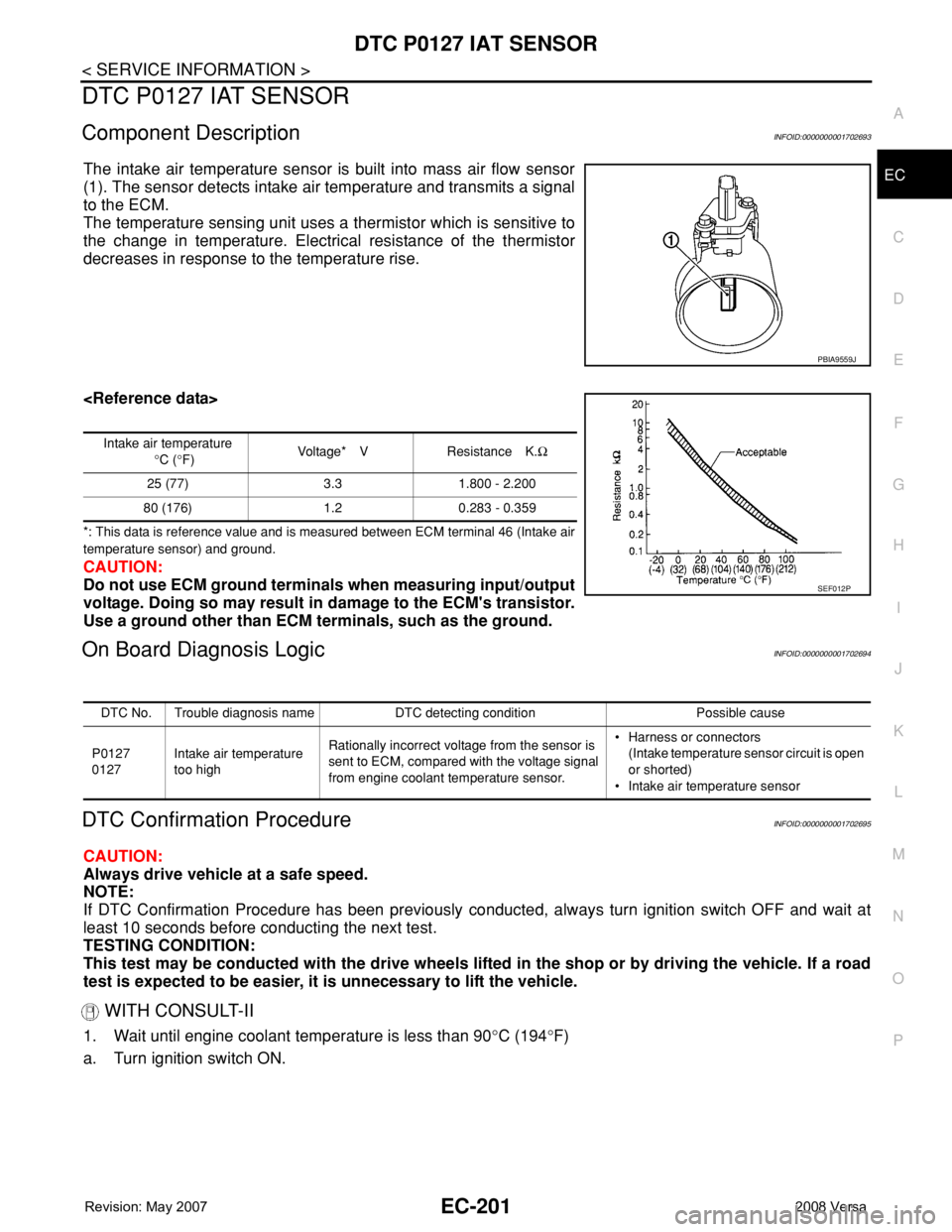
The intake air temperature sensor is built into mass air flow sensor
(1). The sensor detects intake air temperature and transmits a signal
to the ECM.
The temperature sensing unit uses a thermistor which is sensitive to
the change in temperature. Electrical resistance of the thermistor
decreases in response to the temperature rise.
*: This data is reference value and is measured between ECM terminal 46 (Intake air
temperature sensor) and ground.
CAUTION:
Do not use ECM ground terminals when measuring input/output
voltage. Doing so may result in damage to the ECM's transistor.
Use a ground other than ECM terminals, such as the ground.
On Board Diagnosis LogicINFOID:0000000001702694
DTC Confirmation ProcedureINFOID:0000000001702695
CAUTION:
Always drive vehicle at a safe speed.
NOTE:
If DTC Confirmation Procedure has been previously conducted, always turn ignition switch OFF and wait at
least 10 seconds before conducting the next test.
TESTING CONDITION:
This test may be conducted with the drive wheels lifted in the shop or by driving the vehicle. If a road
test is expected to be easier, it is unnecessary to lift the vehicle.
WITH CONSULT-II
1. Wait until engine coolant temperature is less than 90°C (194°F)
a. Turn ignition switch ON.
PBIA9559J
Intake air temperature
°C (°F)Voltage* V Resistance K.Ω
25 (77) 3.3 1.800 - 2.200
80 (176) 1.2 0.283 - 0.359
SEF012P
DTC No. Trouble diagnosis name DTC detecting condition Possible cause
P0127
0127Intake air temperature
too highRationally incorrect voltage from the sensor is
sent to ECM, compared with the voltage signal
from engine coolant temperature sensor.• Harness or connectors
(Intake temperature sensor circuit is open
or shorted)
• Intake air temperature sensor
Page 1358 of 2771

EC-284
< SERVICE INFORMATION >
DTC P0300 - P0304 MULTIPLE CYLINDER MISFIRE, NO. 1 - 4 CYLINDER MIS-
FIRE
DTC P0300 - P0304 MULTIPLE CYLINDER MISFIRE, NO. 1 - 4 CYLINDER
MISFIRE
On Board Diagnosis LogicINFOID:0000000001702790
When a misfire occurs, engine speed will fluctuate. If the engine speed fluctuates enough to cause the crank-
shaft position (CKP) sensor (POS) signal to vary, ECM can determine that a misfire is occurring.
The misfire detection logic consists of the following two conditions.
1. One Trip Detection Logic (Three Way Catalyst Damage)
On the 1st trip that a misfire condition occurs that can damage the three way catalyst (TWC) due to over-
heating, the MIL will blink.
When a misfire condition occurs, the ECM monitors the CKP sensor (POS) signal every 200 engine revo-
lutions for a change.
When the misfire condition decreases to a level that will not damage the TWC, the MIL will turn off.
If another misfire condition occurs that can damage the TWC on a second trip, the MIL will blink.
When the misfire condition decreases to a level that will not damage the TWC, the MIL will remain on.
If another misfire condition occurs that can damage the TWC, the MIL will begin to blink again.
2. Two Trip Detection Logic (Exhaust quality deterioration)
For misfire conditions that will not damage the TWC (but will affect vehicle emissions), the MIL will only
light when the misfire is detected on a second trip. During this condition, the ECM monitors the CKP sen-
sor signal every 1,000 engine revolutions.
A misfire malfunction can be detected on any one cylinder or on multiple cylinders.
DTC Confirmation ProcedureINFOID:0000000001702791
CAUTION:
Always drive vehicle in safe manner according to traffic conditions and obey all traffic laws when driv-
ing.
NOTE:
If DTC Confirmation Procedure has been previously conducted, always turn ignition switch OFF and wait at
least 10 seconds before conducting the next test.
WITH CONSULT-II
Sensor Input Signal to ECM ECM function
Crankshaft position sensor (POS) Engine speed On board diagnosis of misfire
DTC No. Trouble diagnosis name DTC detecting condition Possible cause
P0300
0300Multiple cylinder misfire
detectedMultiple cylinder misfire.• Improper spark plug
• Insufficient compression
• Incorrect fuel pressure
• Fuel injector circuit is open or shorted
• Fuel injector
• Intake air leak
• The ignition signal circuit is open or shorted
• Lack of fuel
• Drive plate or flywheel
• Air fuel ratio (A/F) sensor 1
• Incorrect PCV hose connection P0301
0301No.1 cylinder misfire de-
tectedNo. 1 cylinder misfires.
P0302
0302No. 2 cylinder misfire
detectedNo. 2 cylinder misfires.
P0303
0303No. 3 cylinder misfire
detectedNo. 3 cylinder misfires.
P0304
0304No. 4 cylinder misfire
detectedNo. 4 cylinder misfires.
Page 1388 of 2771
EC-314
< SERVICE INFORMATION >
DTC P0441 EVAP CONTROL SYSTEM
1. Start engine and warm it up to normal operating temperature.
2. Turn ignition switch OFF and wait at least 10 seconds.
3. Start engine and let it idle for at least 70 seconds.
4. Select “PURG FLOW P0441” of “EVAPORATIVE SYSTEM” in “DTC CONFIRMATION” mode with CON-
SULT-II.
5. Touch “START”.
If “COMPLETED” is displayed, go to step 7.
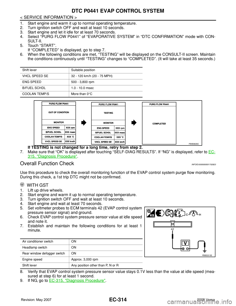
6. When the following conditions are met, “TESTING” will be displayed on the CONSULT-II screen. Maintain
the conditions continuously until “TESTING” changes to “COMPLETED”. (It will take at least 35 seconds.)
If TESTING is not changed for a long time, retry from step 2.
7. Make sure that “OK” is displayed after touching “SELF-DIAG RESULTS”. If “NG” is displayed, refer to EC-
315, "Diagnosis Procedure".
Overall Function CheckINFOID:0000000001702823
Use this procedure to check the overall monitoring function of the EVAP control system purge flow monitoring.
During this check, a 1st trip DTC might not be confirmed.
WITH GST
1. Lift up drive wheels.
2. Start engine and warm it up to normal operating temperature.
3. Turn ignition switch OFF and wait at least 10 seconds.
4. Start engine and wait at least 70 seconds.
5. Set voltmeter probes to ECM terminals 42 (EVAP control system
pressure sensor signal) and ground.
6. Check EVAP control system pressure sensor value at idle speed
and note it.
7. Establish and maintain the following conditions for at least 1
minute.
8. Verify that EVAP control system pressure sensor value stays 0.1V less than the value at idle speed (mea-
sured at step 6) for at least 1 second.
9. If NG, go to EC-315, "
Diagnosis Procedure".
Shift lever Suitable position
VHCL SPEED SE 32 - 120 km/h (20 - 75 MPH)
ENG SPEED 500 - 3,800 rpm
B/FUEL SCHDL 1.0 - 10.0 msec
COOLAN TEMP/S More than 0°C
PBIB0826E
Air conditioner switch ON
Headlamp switch ON
Rear window defogger switch ON
Engine speed Approx. 3,000 rpm
Shift lever Any position other than P, N or R
PBIB3313E
Page 1399 of 2771
DTC P0443 EVAP CANISTER PURGE VOLUME CONTROL SOLENOID VALVE
EC-325
< SERVICE INFORMATION >
C
D
E
F
G
H
I
J
K
L
MA
EC
N
P O
DTC P0443 EVAP CANISTER PURGE VOLUME CONTROL SOLENOID
VA LV E
DescriptionINFOID:0000000001702828
SYSTEM DESCRIPTION
*1: ECM determines the start signal status by the signals of engine speed and battery voltage.
*2: This signal is sent to the ECM though CAN communication line.
This system controls flow rate of fuel vapor from the EVAP canister. The opening of the vapor by-pass pas-
sage in the EVAP canister purge volume control solenoid valve changes to control the flow rate. The EVAP
canister purge volume control solenoid valve repeats ON/OFF operation according to the signal sent from the
ECM. The opening of the valve varies for optimum engine control. The optimum value stored in the ECM is
determined by considering various engine conditions. When the engine is operating, the flow rate of fuel vapor
from the EVAP canister is regulated as the air flow changes.
COMPONENT DESCRIPTION
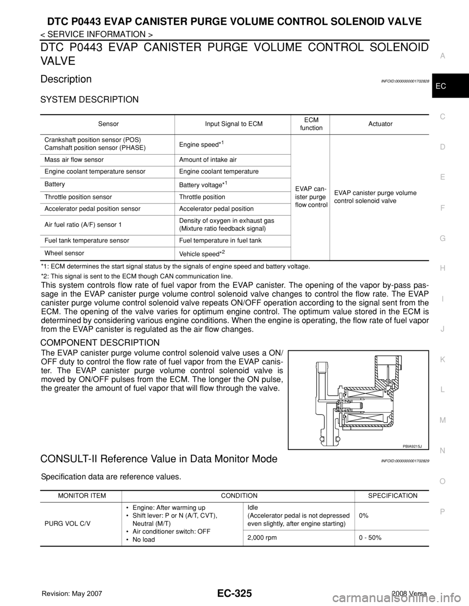
The EVAP canister purge volume control solenoid valve uses a ON/
OFF duty to control the flow rate of fuel vapor from the EVAP canis-
ter. The EVAP canister purge volume control solenoid valve is
moved by ON/OFF pulses from the ECM. The longer the ON pulse,
the greater the amount of fuel vapor that will flow through the valve.
CONSULT-II Reference Value in Data Monitor ModeINFOID:0000000001702829
Specification data are reference values.
Sensor Input Signal to ECMECM
functionActuator
Crankshaft position sensor (POS)
Camshaft position sensor (PHASE)Engine speed*
1
EVAP can-
ister purge
flow controlEVAP canister purge volume
control solenoid valve Mass air flow sensor Amount of intake air
Engine coolant temperature sensor Engine coolant temperature
Battery
Battery voltage*1
Throttle position sensor Throttle position
Accelerator pedal position sensor Accelerator pedal position
Air fuel ratio (A/F) sensor 1Density of oxygen in exhaust gas
(Mixture ratio feedback signal)
Fuel tank temperature sensor Fuel temperature in fuel tank
Wheel sensor
Vehicle speed*
2
PBIA9215J
MONITOR ITEM CONDITION SPECIFICATION
PURG VOL C/V• Engine: After warming up
• Shift lever: P or N (A/T, CVT),
Neutral (M/T)
• Air conditioner switch: OFF
•No loadIdle
(Accelerator pedal is not depressed
even slightly, after engine starting)0%
2,000 rpm 0 - 50%
Page 1406 of 2771
EC-332
< SERVICE INFORMATION >
DTC P0444, P0445 EVAP CANISTER PURGE VOLUME CONTROL SOLENOID
VALVE
DTC P0444, P0445 EVAP CANISTER PURGE VOLUME CONTROL SOLE-
NOID VALVE
DescriptionINFOID:0000000001702836
SYSTEM DESCRIPTION
*1: The ECM determines the start signal status by the signal of engine speed and battery voltage.
*2: This signal is sent to the ECM through CAN communication line.
This system controls flow rate of fuel vapor from the EVAP canister. The opening of the vapor by-pass pas-
sage in the EVAP canister purge volume control solenoid valve changes to control the flow rate. The EVAP
canister purge volume control solenoid valve repeats ON/OFF operation according to the signal sent from the
ECM. The opening of the valve varies for optimum engine control. The optimum value stored in the ECM is
determined by considering various engine conditions. When the engine is operating, the flow rate of fuel vapor
from the EVAP canister is regulated as the air flow changes.
COMPONENT DESCRIPTION
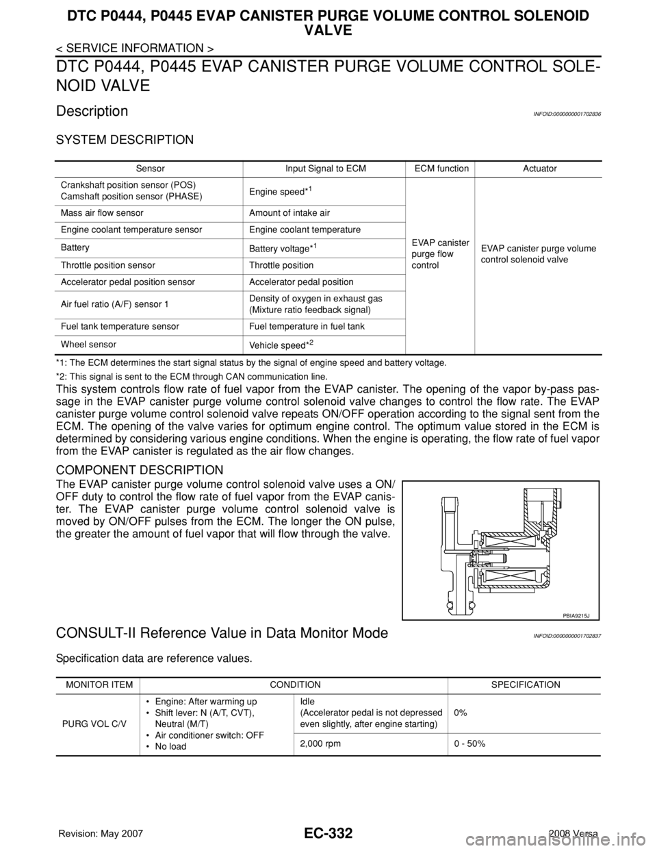
The EVAP canister purge volume control solenoid valve uses a ON/
OFF duty to control the flow rate of fuel vapor from the EVAP canis-
ter. The EVAP canister purge volume control solenoid valve is
moved by ON/OFF pulses from the ECM. The longer the ON pulse,
the greater the amount of fuel vapor that will flow through the valve.
CONSULT-II Reference Value in Data Monitor ModeINFOID:0000000001702837
Specification data are reference values.
Sensor Input Signal to ECM ECM function Actuator
Crankshaft position sensor (POS)
Camshaft position sensor (PHASE)Engine speed*
1
EVAP canister
purge flow
controlEVAP canister purge volume
control solenoid valve Mass air flow sensor Amount of intake air
Engine coolant temperature sensor Engine coolant temperature
Battery
Battery voltage*1
Throttle position sensor Throttle position
Accelerator pedal position sensor Accelerator pedal position
Air fuel ratio (A/F) sensor 1Density of oxygen in exhaust gas
(Mixture ratio feedback signal)
Fuel tank temperature sensor Fuel temperature in fuel tank
Wheel sensor
Vehicle speed*
2
PBIA9215J
MONITOR ITEM CONDITION SPECIFICATION
PURG VOL C/V• Engine: After warming up
• Shift lever: N (A/T, CVT),
Neutral (M/T)
• Air conditioner switch: OFF
• No loadIdle
(Accelerator pedal is not depressed
even slightly, after engine starting)0%
2,000 rpm 0 - 50%