Ipdm NISSAN TIIDA 2008 Service Repair Manual
[x] Cancel search | Manufacturer: NISSAN, Model Year: 2008, Model line: TIIDA, Model: NISSAN TIIDA 2008Pages: 2771, PDF Size: 60.61 MB
Page 101 of 2771
DTC P0705 PARK/NEUTRAL POSITION (PNP) SWITCH
AT-89
< SERVICE INFORMATION >
D
E
F
G
H
I
J
K
L
MA
B
AT
N
O
P
NG >> GO TO 3.
3.CHECK PNP SWITCH
1. Turn ignition switch OFF.
2. Disconnect PNP switch harness connector.
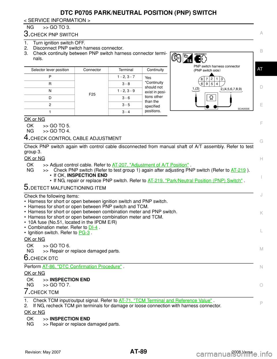
3. Check continuity between PNP switch harness connector termi-
nals.
OK or NG
OK >> GO TO 5.
NG >> GO TO 4.
4.CHECK CONTROL CABLE ADJUSTMENT
Check PNP switch again with control cable disconnected from manual shaft of A/T assembly. Refer to test
group 3.
OK or NG
OK >> Adjust control cable. Refer to AT-207, "Adjustment of A/T Position" .
NG >> Check PNP switch (Refer to test group 1) again after adjusting PNP switch (Refer to AT-219
).
• If OK, INSPECTION END
• If NG, repair or replace PNP switch. Refer to AT-219, "
Park/Neutral Position (PNP) Switch" .
5.DETECT MALFUNCTIONING ITEM
Check the following items:
• Harness for short or open between ignition switch and PNP switch.
• Harness for short or open between PNP switch and TCM.
• Harness for short or open between combination meter and PNP switch.
• Harness for short or open between combination meter and TCM.
• 10A fuse (No.51, located in the IPDM E/R)
• Combination meter. Refer to DI-4
.
• Ignition switch. Refer to PG-3
.
OK or NG
OK >> GO TO 6.
NG >> Repair or replace damaged parts.
6.CHECK DTC
Perform AT-86, "
DTC Confirmation Procedure" .
OK or NG
OK >>INSPECTION END
NG >> GO TO 7.
7.CHECK TCM
1. Check TCM input/output signal. Refer to AT-71, "
TCM Terminal and Reference Value" .
2. If NG, recheck TCM pin terminals for damage or loose connection with harness connector.
OK or NG
OK >>INSPECTION END
NG >> Repair or replace damaged parts.
Selector lever position Connector Terminal Continuity
P
F251 - 2, 3 - 7
Ye s
*Continuity
should not
exist in posi-
tions other
than the
specified
positions. R3 - 8
N 1 - 2, 3 - 9
D3 - 6
23 - 5
13 - 4
SCIA3553E
Page 112 of 2771
AT-100
< SERVICE INFORMATION >
DTC P0720 VEHICLE SPEED SENSOR A/T (REVOLUTION SENSOR)
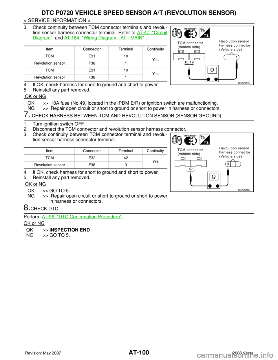
3. Check continuity between TCM connector terminals and revolu-
tion sensor harness connector terminal. Refer to AT-47, "
Circuit
Diagram" and AT-164, "Wiring Diagram - AT - MAIN" .
4. If OK, check harness for short to ground and short to power.
5. Reinstall any part removed.
OK or NG
OK >> 10A fuse (No.49, located in the IPDM E/R) or ignition switch are malfunctioning.
NG >> Repair open circuit or short to ground or short to power in harness or connectors.
7. CHECK HARNESS BETWEEN TCM AND REVOLUTION SENSOR (SENSOR GROUND)
1. Turn ignition switch OFF.
2. Disconnect the TCM connector and revolution sensor harness connector.
3. Check continuity between TCM connector terminal and revolu-
tion sensor harness connector terminal.
4. If OK, check harness for short to ground and short to power.
5. Reinstall any part removed.
OK or NG
OK >> GO TO 5.
NG >> Repair open circuit or short to ground or short to power
in harness or connectors.
8.CHECK DTC
Perform AT-96, "
DTC Confirmation Procedure" .
OK or NG
OK >>INSPECTION END
NG >> GO TO 5.
Item Connector Terminal Continuity
TCM E31 10
Ye s
Revolution sensor F38 1
TCM E31 19
Ye s
Revolution sensor F38 1
SCIA2617E
Item Connector Terminal Continuity
TCM E32 42
Ye s
Revolution sensor F38 3
SCIA2618E
Page 166 of 2771
AT-154
< SERVICE INFORMATION >
DTC BATT/FLUID TEMP SEN (A/T FLUID TEMP SENSOR CIRCUIT AND TCM
POWER SOURCE)
Diagnosis Procedure
INFOID:0000000001703311
1.CHECK TCM POWER SOURCE
1. Turn ignition switch ON. (Do not start engine.)
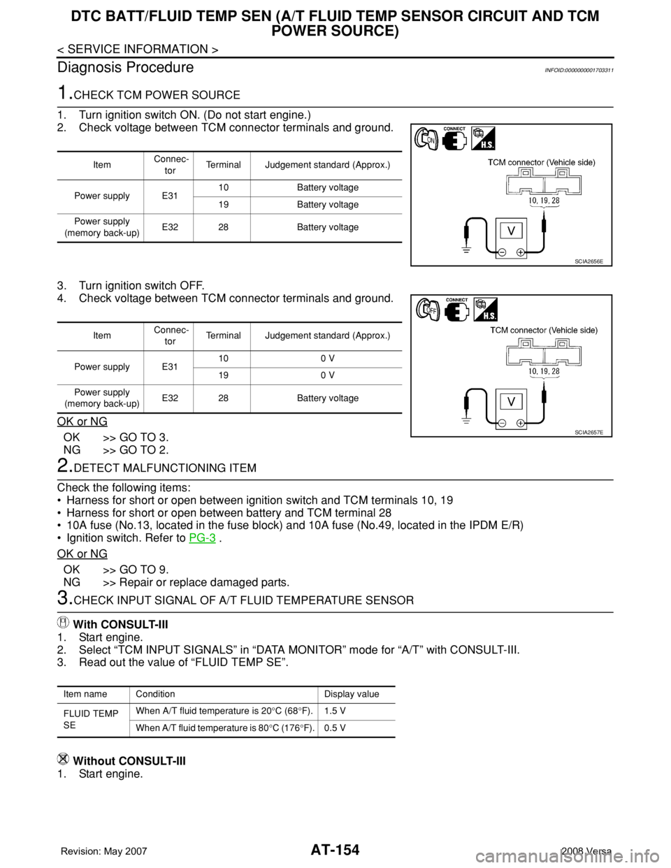
2. Check voltage between TCM connector terminals and ground.
3. Turn ignition switch OFF.
4. Check voltage between TCM connector terminals and ground.
OK or NG
OK >> GO TO 3.
NG >> GO TO 2.
2.DETECT MALFUNCTIONING ITEM
Check the following items:
• Harness for short or open between ignition switch and TCM terminals 10, 19
• Harness for short or open between battery and TCM terminal 28
• 10A fuse (No.13, located in the fuse block) and 10A fuse (No.49, located in the IPDM E/R)
• Ignition switch. Refer to PG-3
.
OK or NG
OK >> GO TO 9.
NG >> Repair or replace damaged parts.
3.CHECK INPUT SIGNAL OF A/T FLUID TEMPERATURE SENSOR
With CONSULT-III
1. Start engine.
2. Select “TCM INPUT SIGNALS” in “DATA MONITOR” mode for “A/T” with CONSULT-III.
3. Read out the value of “FLUID TEMP SE”.
Without CONSULT-III
1. Start engine.
Item Connec-
torTerminal Judgement standard (Approx.)
Power supply E3110 Battery voltage
19 Battery voltage
Power supply
(memory back-up)E32 28 Battery voltage
SCIA2656E
Item Connec-
torTerminal Judgement standard (Approx.)
Power supply E3110 0 V
19 0 V
Power supply
(memory back-up)E32 28 Battery voltage
SCIA2657E
Item name Condition Display value
FLUID TEMP
SEWhen A/T fluid temperature is 20°C (68°F). 1.5 V
When A/T fluid temperature is 80°C (176°F). 0.5 V
Page 174 of 2771
AT-162
< SERVICE INFORMATION >
DTC TURBINE REVOLUTION SENSOR
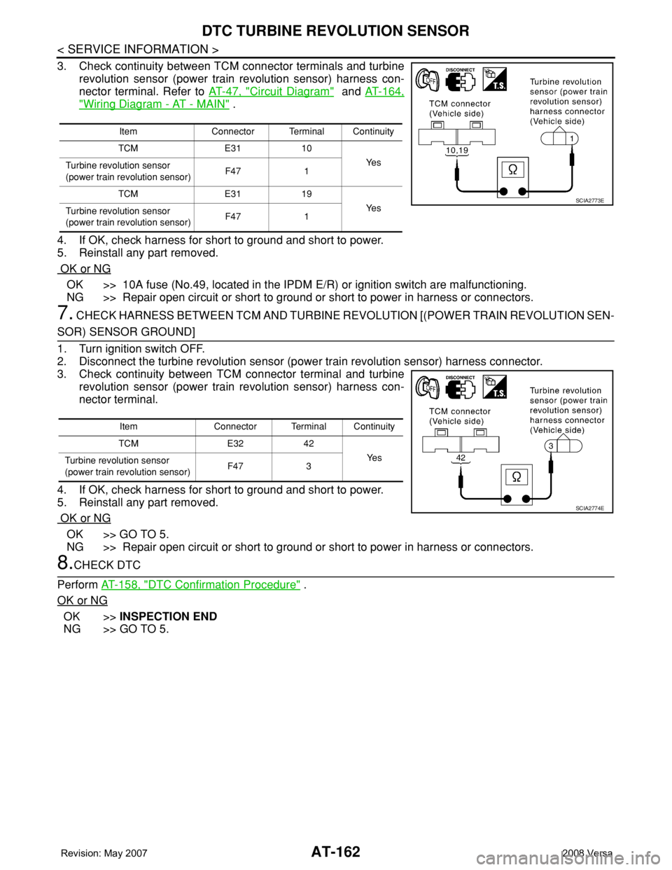
3. Check continuity between TCM connector terminals and turbine
revolution sensor (power train revolution sensor) harness con-
nector terminal. Refer to AT-47, "
Circuit Diagram" and AT-164,
"Wiring Diagram - AT - MAIN" .
4. If OK, check harness for short to ground and short to power.
5. Reinstall any part removed.
OK or NG
OK >> 10A fuse (No.49, located in the IPDM E/R) or ignition switch are malfunctioning.
NG >> Repair open circuit or short to ground or short to power in harness or connectors.
7. CHECK HARNESS BETWEEN TCM AND TURBINE REVOLUTION [(POWER TRAIN REVOLUTION SEN-
SOR) SENSOR GROUND]
1. Turn ignition switch OFF.
2. Disconnect the turbine revolution sensor (power train revolution sensor) harness connector.
3. Check continuity between TCM connector terminal and turbine
revolution sensor (power train revolution sensor) harness con-
nector terminal.
4. If OK, check harness for short to ground and short to power.
5. Reinstall any part removed.
OK or NG
OK >> GO TO 5.
NG >> Repair open circuit or short to ground or short to power in harness or connectors.
8.CHECK DTC
Perform AT-158, "
DTC Confirmation Procedure" .
OK or NG
OK >>INSPECTION END
NG >> GO TO 5.
Item Connector Terminal Continuity
TCM E31 10
Ye s
Turbine revolution sensor
(power train revolution sensor)F47 1
TCM E31 19
Ye s
Turbine revolution sensor
(power train revolution sensor)F47 1
SCIA2773E
Item Connector Terminal Continuity
TCM E32 42
Ye s
Turbine revolution sensor
(power train revolution sensor)F47 3
SCIA2774E
Page 177 of 2771
MAIN POWER SUPPLY AND GROUND CIRCUIT
AT-165
< SERVICE INFORMATION >
D
E
F
G
H
I
J
K
L
MA
B
AT
N
O
P
Diagnosis ProcedureINFOID:0000000001703326
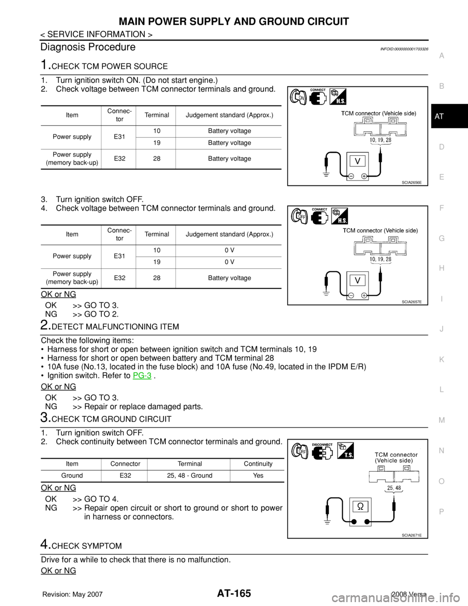
1.CHECK TCM POWER SOURCE
1. Turn ignition switch ON. (Do not start engine.)
2. Check voltage between TCM connector terminals and ground.
3. Turn ignition switch OFF.
4. Check voltage between TCM connector terminals and ground.
OK or NG
OK >> GO TO 3.
NG >> GO TO 2.
2.DETECT MALFUNCTIONING ITEM
Check the following items:
• Harness for short or open between ignition switch and TCM terminals 10, 19
• Harness for short or open between battery and TCM terminal 28
• 10A fuse (No.13, located in the fuse block) and 10A fuse (No.49, located in the IPDM E/R)
• Ignition switch. Refer to PG-3
.
OK or NG
OK >> GO TO 3.
NG >> Repair or replace damaged parts.
3.CHECK TCM GROUND CIRCUIT
1. Turn ignition switch OFF.
2. Check continuity between TCM connector terminals and ground.
OK or NG
OK >> GO TO 4.
NG >> Repair open circuit or short to ground or short to power
in harness or connectors.
4.CHECK SYMPTOM
Drive for a while to check that there is no malfunction.
OK or NG
ItemConnec-
torTerminal Judgement standard (Approx.)
Power supply E3110 Battery voltage
19 Battery voltage
Power supply
(memory back-up)E32 28 Battery voltage
SCIA2656E
ItemConnec-
torTerminal Judgement standard (Approx.)
Power supply E3110 0 V
19 0 V
Power supply
(memory back-up)E32 28 Battery voltage
SCIA2657E
Item Connector Terminal Continuity
Ground E32 25, 48 - Ground Yes
SCIA2671E
Page 181 of 2771
PNP, OD SWITCH AND CLOSED THROTTLE, WIDE OPEN THROTTLE POSI-
TION SIGNAL CIRCUIT
AT-169
< SERVICE INFORMATION >
D
E
F
G
H
I
J
K
L
MA
B
AT
N
O
P
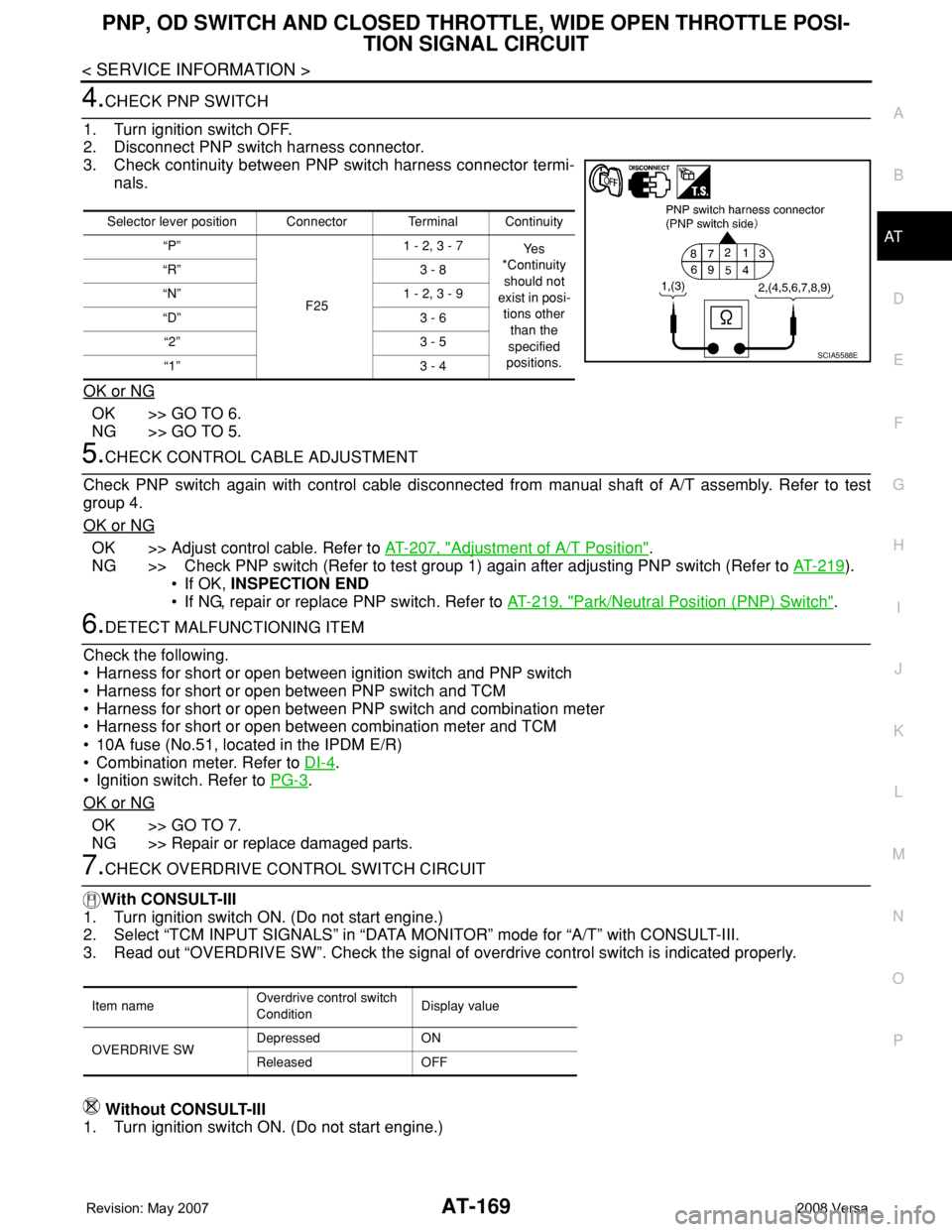
4.CHECK PNP SWITCH
1. Turn ignition switch OFF.
2. Disconnect PNP switch harness connector.
3. Check continuity between PNP switch harness connector termi-
nals.
OK or NG
OK >> GO TO 6.
NG >> GO TO 5.
5.CHECK CONTROL CABLE ADJUSTMENT
Check PNP switch again with control cable disconnected from manual shaft of A/T assembly. Refer to test
group 4.
OK or NG
OK >> Adjust control cable. Refer to AT-207, "Adjustment of A/T Position".
NG >> Check PNP switch (Refer to test group 1) again after adjusting PNP switch (Refer to AT-219
).
• If OK, INSPECTION END
• If NG, repair or replace PNP switch. Refer to AT-219, "
Park/Neutral Position (PNP) Switch".
6.DETECT MALFUNCTIONING ITEM
Check the following.
• Harness for short or open between ignition switch and PNP switch
• Harness for short or open between PNP switch and TCM
• Harness for short or open between PNP switch and combination meter
• Harness for short or open between combination meter and TCM
• 10A fuse (No.51, located in the IPDM E/R)
• Combination meter. Refer to DI-4
.
• Ignition switch. Refer to PG-3
.
OK or NG
OK >> GO TO 7.
NG >> Repair or replace damaged parts.
7.CHECK OVERDRIVE CONTROL SWITCH CIRCUIT
With CONSULT-III
1. Turn ignition switch ON. (Do not start engine.)
2. Select “TCM INPUT SIGNALS” in “DATA MONITOR” mode for “A/T” with CONSULT-III.
3. Read out “OVERDRIVE SW”. Check the signal of overdrive control switch is indicated properly.
Without CONSULT-III
1. Turn ignition switch ON. (Do not start engine.)
Selector lever position Connector Terminal Continuity
“P”
F251 - 2, 3 - 7
Ye s
*Continuity
should not
exist in posi-
tions other
than the
specified
positions. “R” 3 - 8
“N” 1 - 2, 3 - 9
“D” 3 - 6
“2” 3 - 5
“1” 3 - 4
SCIA5588E
Item nameOverdrive control switch
ConditionDisplay value
OVERDRIVE SWDepressed ON
Released OFF
Page 189 of 2771
TROUBLE DIAGNOSIS FOR SYMPTOMS
AT-177
< SERVICE INFORMATION >
D
E
F
G
H
I
J
K
L
MA
B
AT
N
O
P
OD OFF indicator lamp does not come on for about 2 seconds when turning ignition switch to ON.
DIAGNOSTIC PROCEDURE
1.CHECK CAN COMMUNICATION LINE
Perform self-diagnosis. Refer to AT-73, "
CONSULT-III Function (A/T)" .
Is a malfunction in CAN communication indicated in the results?
YES >> Check CAN communication line. Refer to AT- 8 3 .
NO >> GO TO 2.
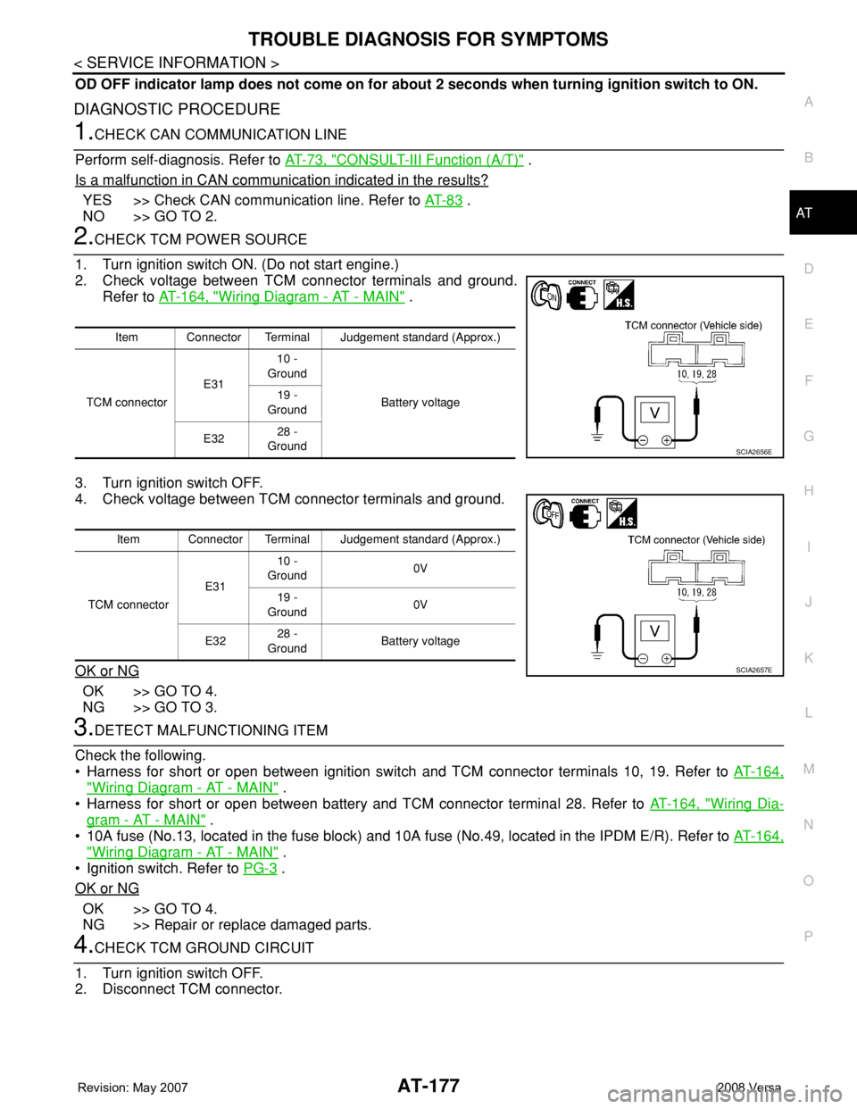
2.CHECK TCM POWER SOURCE
1. Turn ignition switch ON. (Do not start engine.)
2. Check voltage between TCM connector terminals and ground.
Refer to AT-164, "
Wiring Diagram - AT - MAIN" .
3. Turn ignition switch OFF.
4. Check voltage between TCM connector terminals and ground.
OK or NG
OK >> GO TO 4.
NG >> GO TO 3.
3.DETECT MALFUNCTIONING ITEM
Check the following.
• Harness for short or open between ignition switch and TCM connector terminals 10, 19. Refer to AT-164,
"Wiring Diagram - AT - MAIN" .
• Harness for short or open between battery and TCM connector terminal 28. Refer to AT-164, "
Wiring Dia-
gram - AT - MAIN" .
• 10A fuse (No.13, located in the fuse block) and 10A fuse (No.49, located in the IPDM E/R). Refer to AT-164,
"Wiring Diagram - AT - MAIN" .
• Ignition switch. Refer to PG-3
.
OK or NG
OK >> GO TO 4.
NG >> Repair or replace damaged parts.
4.CHECK TCM GROUND CIRCUIT
1. Turn ignition switch OFF.
2. Disconnect TCM connector.
Item Connector Terminal Judgement standard (Approx.)
TCM connectorE3110 -
Ground
Battery voltage 19 -
Ground
E3228 -
Ground
SCIA2656E
Item Connector Terminal Judgement standard (Approx.)
TCM connectorE3110 -
Ground0V
19 -
Ground0V
E3228 -
GroundBattery voltage
SCIA2657E
Page 420 of 2771
BCS-4
< SERVICE INFORMATION >
BCM (BODY CONTROL MODULE)
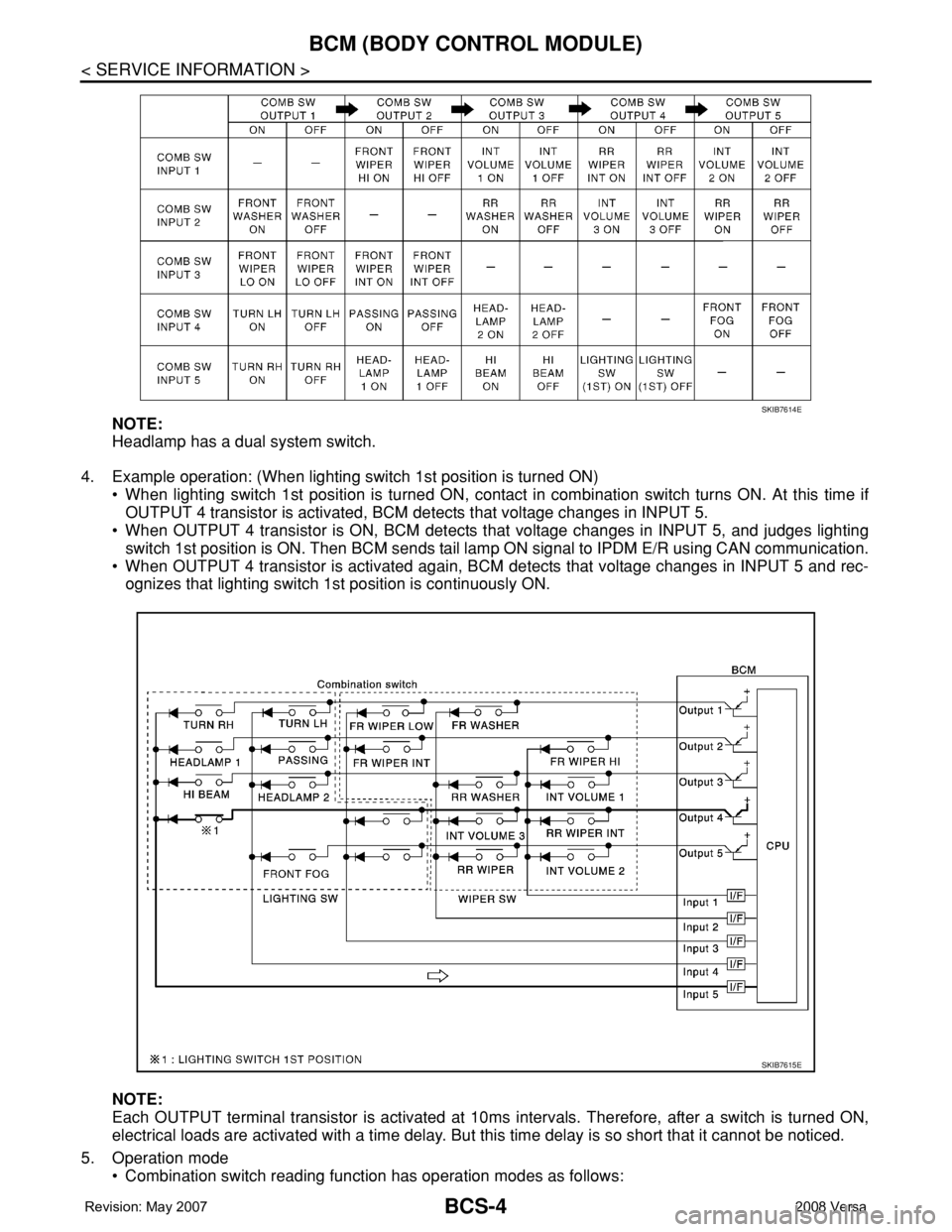
NOTE:
Headlamp has a dual system switch.
4. Example operation: (When lighting switch 1st position is turned ON)
• When lighting switch 1st position is turned ON, contact in combination switch turns ON. At this time if
OUTPUT 4 transistor is activated, BCM detects that voltage changes in INPUT 5.
• When OUTPUT 4 transistor is ON, BCM detects that voltage changes in INPUT 5, and judges lighting
switch 1st position is ON. Then BCM sends tail lamp ON signal to IPDM E/R using CAN communication.
• When OUTPUT 4 transistor is activated again, BCM detects that voltage changes in INPUT 5 and rec-
ognizes that lighting switch 1st position is continuously ON.
NOTE:
Each OUTPUT terminal transistor is activated at 10ms intervals. Therefore, after a switch is turned ON,
electrical loads are activated with a time delay. But this time delay is so short that it cannot be noticed.
5. Operation mode
• Combination switch reading function has operation modes as follows:
SKIB7614E
SKIB7615E
Page 421 of 2771
BCM (BODY CONTROL MODULE)
BCS-5
< SERVICE INFORMATION >
C
D
E
F
G
H
I
J
L
MA
B
BCS
N
O
P
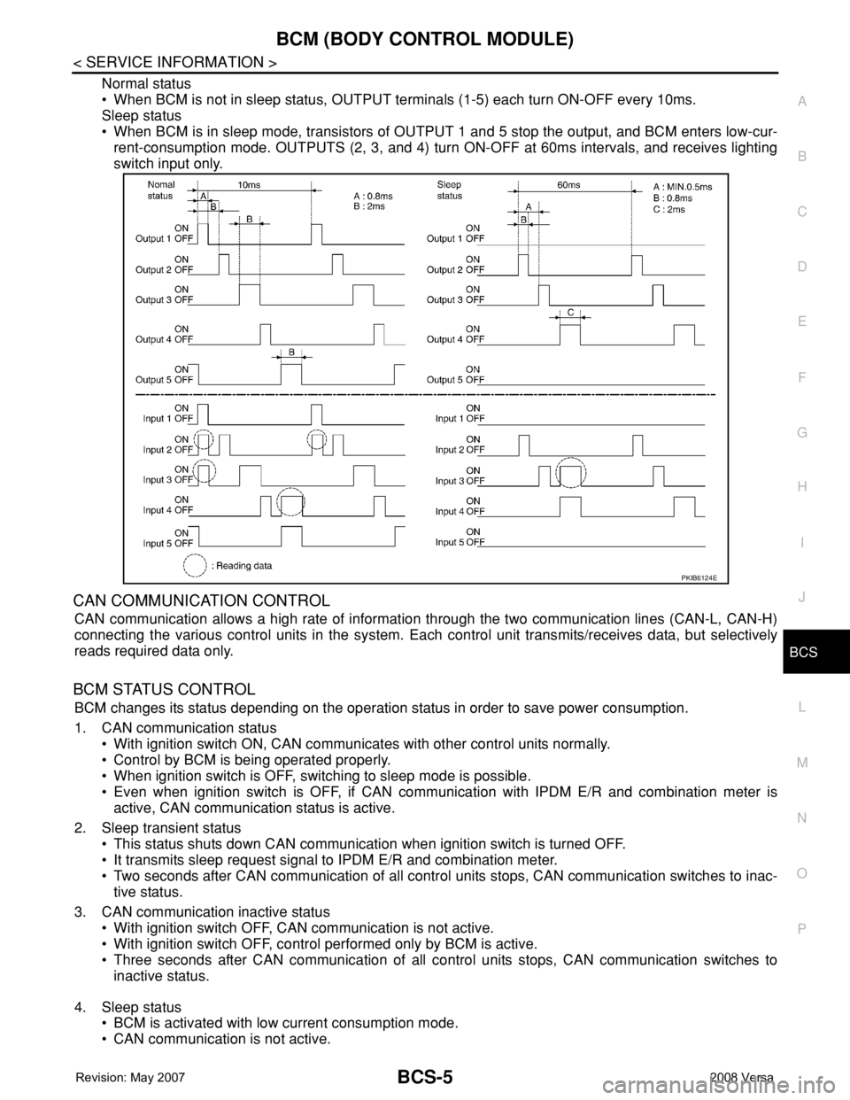
Normal status
• When BCM is not in sleep status, OUTPUT terminals (1-5) each turn ON-OFF every 10ms.
Sleep status
• When BCM is in sleep mode, transistors of OUTPUT 1 and 5 stop the output, and BCM enters low-cur-
rent-consumption mode. OUTPUTS (2, 3, and 4) turn ON-OFF at 60ms intervals, and receives lighting
switch input only.
CAN COMMUNICATION CONTROL
CAN communication allows a high rate of information through the two communication lines (CAN-L, CAN-H)
connecting the various control units in the system. Each control unit transmits/receives data, but selectively
reads required data only.
BCM STATUS CONTROL
BCM changes its status depending on the operation status in order to save power consumption.
1. CAN communication status
• With ignition switch ON, CAN communicates with other control units normally.
• Control by BCM is being operated properly.
• When ignition switch is OFF, switching to sleep mode is possible.
• Even when ignition switch is OFF, if CAN communication with IPDM E/R and combination meter is
active, CAN communication status is active.
2. Sleep transient status
• This status shuts down CAN communication when ignition switch is turned OFF.
• It transmits sleep request signal to IPDM E/R and combination meter.
• Two seconds after CAN communication of all control units stops, CAN communication switches to inac-
tive status.
3. CAN communication inactive status
• With ignition switch OFF, CAN communication is not active.
• With ignition switch OFF, control performed only by BCM is active.
• Three seconds after CAN communication of all control units stops, CAN communication switches to
inactive status.
4. Sleep status
• BCM is activated with low current consumption mode.
• CAN communication is not active.
PKIB6124E
Page 422 of 2771
BCS-6
< SERVICE INFORMATION >
BCM (BODY CONTROL MODULE)
• When CAN communication operation is detected, it switches to CAN communication status.
• When a state of the following switches changes, it switches to CAN communication state:
- Ignition switch
- Key switch (without Intelligent Key)
- Key switch and ignition knob switch (with Intelligent Key)
- Hazard switch
- Door lock/unlock switch
- Front door switch (LH, RH)
- Rear door switch (LH, RH)
- Back door lock assembly (Hatchback)
- Trunk key cylinder switch (Sedan)
- Trunk lamp switch and trunk release solenoid (Sedan)
- Combination switch (passing, lighting switch 1st position, front fog lamp)
- Keyfob (lock/unlock signal)
- Front door key cylinder switch LH
• When control performed only by BCM is required by switch, it shifts to CAN communication inactive
mode.
• Status of combination switch reading function is changed.
SYSTEMS CONTROLLED BY BCM DIRECTLY
• Power door lock system. Refer to BL-22 .
• Remote keyless entry system. Refer to BL-51
.
• Power window system. Refer to GW-18
. NOTE
• Sunroof system. Refer to RF-10. NOTE
• Room lamp timer. Refer to LT- 8 9 .
• Rear wiper and washer system. Refer to WW-24
.
NOTE:
Power supply only. No system control.
SYSTEMS CONTROLLED BY BCM AND IPDM E/R
• Panic system. Refer to BL-51 .
• Vehicle security (theft warning) system. Refer to BL-187
.
• NVIS(NATS) system. Refer to BL-210
.
• Headlamp, tail lamp and battery saver control systems. Refer to LT- 7 2
, LT- 4 or LT- 2 5 .
• Front fog lamp. Refer to LT- 3 9
.
• Front wiper and washer system. Refer to WW-3
.
• Rear window defogger system. Refer to GW-49
.
SYSTEMS CONTROLLED BY BCM AND COMBINATION METER
• Warning chime. Refer to DI-41 .
• Turn signal and hazard warning lamps. Refer to LT- 4 8
.
SYSTEMS CONTROLLED BY BCM AND INTELLIGENT KEY UNIT
• Intelligent Key system. Refer to BL-74 .
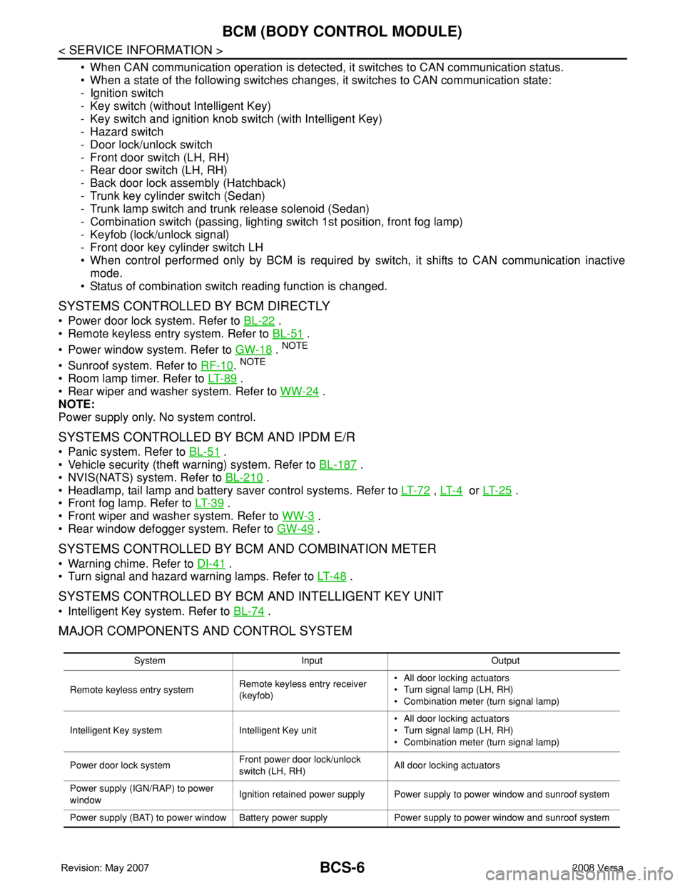
MAJOR COMPONENTS AND CONTROL SYSTEM
System Input Output
Remote keyless entry systemRemote keyless entry receiver
(keyfob)• All door locking actuators
• Turn signal lamp (LH, RH)
• Combination meter (turn signal lamp)
Intelligent Key system Intelligent Key unit• All door locking actuators
• Turn signal lamp (LH, RH)
• Combination meter (turn signal lamp)
Power door lock systemFront power door lock/unlock
switch (LH, RH)All door locking actuators
Power supply (IGN/RAP) to power
windowIgnition retained power supply Power supply to power window and sunroof system
Power supply (BAT) to power window Battery power supply Power supply to power window and sunroof system