Pressure NISSAN TIIDA 2008 Service Repair Manual
[x] Cancel search | Manufacturer: NISSAN, Model Year: 2008, Model line: TIIDA, Model: NISSAN TIIDA 2008Pages: 2771, PDF Size: 60.61 MB
Page 4 of 2771

2008
QUICK REFERENCE CHART: VERSA
QUICK REFERENCE CHART: VERSA
Engine Tune-up DataINFOID:0000000001903528
GENERAL SPECIFICATIONS
SPARK PLUG
Unit: mm (in)
Front Wheel Alignment (Unladen*)INFOID:0000000001903529
Engine typeMR18DE
Cylinder arrangement In-line 4
Displacement cm
3 (cu in)1,797 (109.65)
Bore and stroke mm (in) 84.0 x 81.1 (3.307 x 3.192)
Valve arrangement DOHC
Firing order 1-3-4-2
Number of piston rings Compression 2
Oil 1
Compression ratio 9.9
Compression pressure
kPa (bar, kg/cm
2 , psi) / 250 rpm Standard 1,500 (15.0, 15.3, 217.6)
Minimum 1,200 (12.0, 12.2, 174)
Differential limit between cylinders 100 (1.0, 1.0, 15)
Plug type
Iridium-tipped TYPE
Make DENSO
Standard type FXE20HR11
Spark plug gap Nominal: 1.1 (0.043)
Camber
Degree minute (Decimal degree)RH
Minimum - 1
° 05 ′ (- 1.08 °)
Nominal - 0 ° 20 ′ (- 0.33 °)
Maximum 0 ° 25 ′ (0.42 °)
LH Minimum - 0
° 55 ′ (- 0.92 °)
Nominal - 0 ° 10 ′ (- 0.17 °)
Maximum 0 ° 35 ′ (0.58 °)
Left and right difference
(RH - LH) Minimum -0
° 45 ′ (-0.75 °) or less
Nominal -0 ° 12 ′ (-0.20 °) or less
Maximum 0 ° 21 ′ (0.35 °) or less
Caster
Degree minute (Decimal degree) RH
Minimum 4
° 05 ′ (4.08 °)
Nominal 4 ° 50 ′ (4.83 °)
Maximum 5 ° 35 ′ (5.58 °)
LH Minimum 3
° 55 ′ (3.92 °)
Nominal 4 ° 40 ′ (4.67 °)
Maximum 5 ° 25 ′ (5.42 °)
Left and right difference
(RH - LH) Minimum -0
° 21 ′ (-0.35 °) or less
Nominal 0 ° 12 ′ (0.20 °) or less
Maximum 0 ° 45 ′ (0.75 °) or less
Page 13 of 2771

AT-1
TRANSMISSION/TRANSAXLE
D
E
F
G
H
I
J
K
L
M
SECTION AT
A
B
AT
N
O
P
CONTENTS
AUTOMATIC TRANSAXLE
SERVICE INFORMATION ............................5
INDEX FOR DTC .................................................5
Alphabetical Index .....................................................5
DTC No. Index ..........................................................5
PRECAUTIONS ...................................................7
Precaution for Supplemental Restraint System
(SRS) "AIR BAG" and "SEAT BELT PRE-TEN-
SIONER" ...................................................................
7
Precaution Necessary for Steering Wheel Rota-
tion After Battery Disconnect .....................................
7
Precaution for On Board Diagnosis (OBD) System
of A/T and Engine .....................................................
7
Precaution .................................................................8
Service Notice or Precaution .....................................9
PREPARATION ..................................................10
Special Service Tool ...............................................10
Commercial Service Tool ........................................13
A/T FLUID ...........................................................15
Checking A/T Fluid ..................................................15
Changing A/T Fluid .................................................15
A/T Fluid Cooler Cleaning .......................................16
A/T CONTROL SYSTEM ....................................19
Cross-Sectional View ..............................................19
Shift Mechanism ......................................................19
TCM Function ..........................................................27
CAN Communication ...............................................28
Input/Output Signal of TCM .....................................28
Line Pressure Control .............................................29
Shift Control ............................................................30
Lock-up Control .......................................................31
Engine Brake Control (Overrun Clutch Control) ......32
Control Valve ...........................................................34
Centrifugal Cancel Mechanism ...............................34
ON BOARD DIAGNOSTIC (OBD) SYSTEM ......36
Introduction .............................................................36
OBD-II Function for A/T System ..............................36
One or Two Trip Detection Logic of OBD-II .............36
OBD-II Diagnostic Trouble Code (DTC) ..................36
Malfunction Indicator Lamp (MIL) ............................38
TROUBLE DIAGNOSIS ....................................39
DTC Inspection Priority Chart ..................................39
Fail-Safe ..................................................................39
How to Perform Trouble Diagnosis for Quick and
Accurate Repair .......................................................
40
A/T Electrical Parts Location ...................................46
Circuit Diagram ........................................................47
Inspections Before Trouble Diagnosis .....................48
Road Test ................................................................52
Check Before Engine Is Started ..............................53
Check at Idle ............................................................53
Cruise Test - Part 1 .................................................55
Cruise Test - Part 2 .................................................58
Cruise Test - Part 3 .................................................59
Vehicle Speed at Which Gear Shifting Occurs ........61
Vehicle Speed at Which Lock-up Occurs/Releas-
es .............................................................................
61
Symptom Chart ........................................................61
TCM Terminal and Reference Value .......................71
CONSULT-III Function (A/T) ...................................73
Diagnosis Procedure without CONSULT-III ............78
DTC U1000 CAN COMMUNICATION LINE .....83
Description ...............................................................83
On Board Diagnosis Logic .......................................83
Possible Cause ........................................................83
DTC Confirmation Procedure ..................................83
Wiring Diagram - AT - CAN .....................................84
Diagnosis Procedure ...............................................85
DTC P0705 PARK/NEUTRAL POSITION
(PNP) SWITCH ..................................................
86
Description ...............................................................86
CONSULT-III Reference Value in Data Monitor
Mode ........................................................................
86
On Board Diagnosis Logic .......................................86
Possible Cause ........................................................86
Page 14 of 2771

AT-2
DTC Confirmation Procedure .................................86
Wiring Diagram - AT - PNP/SW ..............................87
Diagnosis Procedure ..............................................88
Component Inspection ............................................90
DTC P0710 A/T FLUID TEMPERATURE SEN-
SOR CIRCUIT ....................................................
91
Description ..............................................................91
CONSULT-III Reference Value in Data Monitor
Mode .......................................................................
91
On Board Diagnosis Logic ......................................91
Possible Cause .......................................................91
DTC Confirmation Procedure .................................91
Wiring Diagram - AT - FTS .....................................92
Diagnosis Procedure ..............................................92
Component Inspection ............................................95
DTC P0720 VEHICLE SPEED SENSOR A/T
(REVOLUTION SENSOR) .................................
96
Description ..............................................................96
CONSULT-III Reference Value in Data Monitor
Mode .......................................................................
96
On Board Diagnosis Logic ......................................96
Possible Cause .......................................................96
DTC Confirmation Procedure .................................96
Wiring Diagram - AT - VSSA/T ...............................97
Diagnosis Procedure ..............................................98
DTC P0725 ENGINE SPEED SIGNAL ............101
Description .............................................................101
CONSULT-III Reference Value in Data Monitor
Mode ......................................................................
101
On Board Diagnosis Logic .....................................101
Possible Cause ......................................................101
DTC Confirmation Procedure ................................101
Wiring Diagram - AT - ENGSS ..............................102
Diagnosis Procedure .............................................103
DTC P0731 A/T 1ST GEAR FUNCTION .........105
Description .............................................................105
On Board Diagnosis Logic .....................................105
Possible Cause ......................................................105
DTC Confirmation Procedure ................................105
Diagnosis Procedure .............................................106
DTC P0732 A/T 2ND GEAR FUNCTION .........108
Description .............................................................108
On Board Diagnosis Logic .....................................108
Possible Cause ......................................................108
DTC Confirmation Procedure ................................108
Diagnosis Procedure .............................................109
DTC P0733 A/T 3RD GEAR FUNCTION .........111
Description .............................................................111
On Board Diagnosis Logic .....................................111
Possible Cause ......................................................111
DTC Confirmation Procedure ................................111
Diagnosis Procedure .............................................112
DTC P0734 A/T 4TH GEAR FUNCTION .........114
Description ............................................................114
CONSULT-III Reference Value in Data Monitor
Mode .....................................................................
114
On Board Diagnosis Logic ....................................114
Possible Cause .....................................................114
DTC Confirmation Procedure ................................114
Diagnosis Procedure .............................................115
DTC P0740 TORQUE CONVERTER CLUTCH
SOLENOID VALVE ..........................................
119
Description ............................................................119
CONSULT-III Reference Value in Data Monitor
Mode .....................................................................
119
On Board Diagnosis Logic ....................................119
Possible Cause .....................................................119
DTC Confirmation Procedure ................................119
Wiring Diagram - AT - TCV ...................................120
Diagnosis Procedure .............................................121
Component Inspection ..........................................122
DTC P0744 A/T TCC S/V FUNCTION (LOCK-
UP) ....................................................................
124
Description ............................................................124
CONSULT-III Reference Value in Data Monitor
Mode .....................................................................
124
On Board Diagnosis Logic ....................................124
Possible Cause .....................................................124
DTC Confirmation Procedure ................................124
Diagnosis Procedure .............................................125
DTC P0745 LINE PRESSURE SOLENOID
VALVE ..............................................................
129
Description ............................................................129
CONSULT-III Reference Value in Data Monitor
Mode .....................................................................
129
On Board Diagnosis Logic ....................................129
Possible Cause .....................................................129
DTC Confirmation Procedure ................................129
Wiring Diagram - AT - LPSV .................................130
Diagnosis Procedure .............................................131
Component Inspection ..........................................133
DTC P0750 SHIFT SOLENOID VALVE A ........134
Description ............................................................134
CONSULT-III Reference Value in Data Monitor
Mode .....................................................................
134
On Board Diagnosis Logic ....................................134
Possible Cause .....................................................134
DTC Confirmation Procedure ................................134
Wiring Diagram - AT - SSV/A ................................135
Diagnosis Procedure .............................................136
Component Inspection ..........................................137
DTC P0755 SHIFT SOLENOID VALVE B ........139
Description ............................................................139
CONSULT-III Reference Value in Data Monitor
Mode .....................................................................
139
On Board Diagnosis Logic ....................................139
Possible Cause .....................................................139
DTC Confirmation Procedure ................................139
Page 16 of 2771

AT-4
Diagnosis Procedure .............................................210
KEY INTERLOCK CABLE ...............................213
Removal and Installation .......................................213
ON-VEHICLE SERVICE ..................................216
Control Valve Assembly and Accumulators ...........216
Park/Neutral Position (PNP) Switch ......................219
Revolution Sensor .................................................221
Turbine Revolution Sensor (Power Train Revolu-
tion Sensor) ...........................................................
222
Differential Side Oil Seal ........................................223
AIR BREATHER HOSE ...................................225
Removal and Installation .......................................225
TRANSAXLE ASSEMBLY ..............................226
Removal and Installation .......................................226
OVERHAUL .....................................................230
Component ............................................................230
Oil Channel ............................................................237
Location of Adjusting Shims, Needle Bearings and
Thrust Washers .....................................................
238
Location of Snap Rings .........................................239
DISASSEMBLY ...............................................240
Disassembly ..........................................................240
REPAIR FOR COMPONENT PARTS ..............257
Manual Shaft .........................................................257
Oil Pump ................................................................260
Control Valve Assembly ........................................263
Control Valve Upper Body .....................................272
Control Valve Lower Body .....................................276
Reverse Clutch ......................................................279
High Clutch ............................................................284
Forward and Overrun Clutches .............................288
Low & Reverse Brake ............................................295
Rear Internal Gear and Forward Clutch Hub .........299
Output Shaft, Output Gear, Idler Gear, Reduction
Pinion Gear and Bearing Retainer .........................
302
Band Servo Piston Assembly ................................307
Final Drive .............................................................313
ASSEMBLY ......................................................318
Assembly (1) .........................................................318
Adjustment (1) .......................................................319
Assembly (2) .........................................................325
Adjustment (2) .......................................................330
Assembly (3) .........................................................333
SERVICE DATA AND SPECIFICATIONS
(SDS) ................................................................
341
General Specification ............................................341
Vehicle Speed at Which Gear Shifting Occurs .....341
Vehicle Speed at When Lock-up Occurs/Releases
.
341
Stall Speed ............................................................341
Line Pressure ........................................................341
Adjusting shims, Needle Bearings, Thrust Wash-
ers and Snap Rings ..............................................
341
Control Valves .......................................................343
Accumulator ..........................................................343
Clutches and Brakes .............................................343
Final Drive .............................................................345
Planetary Carrier ...................................................345
Oil Pump ...............................................................345
Input Shaft .............................................................345
Reduction Pinion Gear ..........................................345
Band Servo ...........................................................345
Output Shaft ..........................................................346
Bearing Retainer ...................................................346
Total End Play .......................................................346
Reverse Clutch End Play ......................................346
Removal and Installation .......................................346
Shift Solenoid Valves ............................................346
Solenoid Valves ....................................................346
A/T Fluid Temperature Sensor ..............................347
Revolution Sensor .................................................347
Dropping Resistor .................................................347
Turbine Revolution Sensor (Power Train Revolu-
tion Sensor) ...........................................................
347
Page 17 of 2771

INDEX FOR DTC
AT-5
< SERVICE INFORMATION >
D
E
F
G
H
I
J
K
L
MA
B
AT
N
O
P
SERVICE INFORMATION
INDEX FOR DTC
Alphabetical IndexINFOID:0000000001703149
NOTE:
If DTC “CAN COMM CIRCUIT” is displayed with other DTCs, first perform the trouble diagnosis for
DTC “CAN COMM CIRCUIT”. Refer to AT- 8 3
.
*1: These numbers is prescribed by SAE J2012.
*2: When the fail-safe operation occurs, the MIL illuminates.
*3: The MIL illuminates when both the “Revolution sensor signal” and the “Vehicle speed sensor signal” meet the fail-safe condition at
the same time.
DTC No. IndexINFOID:0000000001703150
NOTE:
If DTC “CAN COMM CIRCUIT” is displayed with other DTCs, first perform the trouble diagnosis for
DTC “CAN COMM CIRCUIT”. Refer to AT- 8 3
.
Items
(CONSULT-III screen terms)DTC
Reference page
CONSULT-III or GST
*1
A/T 1ST GR FNCTN P0731AT-105
A/T 2ND GR FNCTN P0732AT-108
A/T 3RD GR FNCTN P0733AT- 111
A/T 4TH GR FNCTN P0734AT- 11 4
A/T TCC S/V FNCTN P0744AT-124
ATF TEMP SEN/CIRC P0710AT- 9 1
BATT/FLUID TEMP SEN —AT-152
CAN COMM CIRCUIT U1000AT- 8 3
CONTROL UNIT (RAM) —AT-163
CONTROL UNIT (ROM) —AT-163
ENGINE SPEED SIG P0725AT-101
LINE PRESSURE S/V P0745AT-129
OVERRUN CLUTCH S/V P1760AT-144
PNP SW/CIRC P0705AT- 8 6
SHIFT SOLENOID/V A*2P0750AT-134
SHIFT SOLENOID/V B*2P0755AT-139
T/C CLUTCH SOL/V P0740AT- 11 9
TURBINE SENSOR —AT-158
VHCL SPEED SEN-A/T*3P0720AT- 9 6
VHCL SPEED SEN-MTR —AT-149
DTC
Items
(CONSULT-III screen terms) Reference page
CONSULT-III or GST
*1
P0705 PNP SW/CIRCAT- 8 6
P0710 ATF TEMP SEN/CIRCAT- 9 1
P0720
VHCL SPEED SEN-A/T*3AT- 9 6
P0725 ENGINE SPEED SIGAT- 1 0 1
P0731 A/T 1ST GR FNCTNAT- 1 0 5
Page 18 of 2771
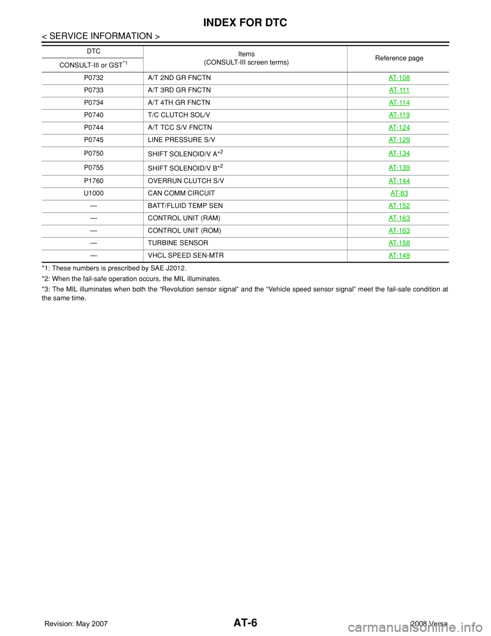
AT-6
< SERVICE INFORMATION >
INDEX FOR DTC
*1: These numbers is prescribed by SAE J2012.
*2: When the fail-safe operation occurs, the MIL illuminates.
*3: The MIL illuminates when both the “Revolution sensor signal” and the “Vehicle speed sensor signal” meet the fail-safe condition at
the same time.P0732 A/T 2ND GR FNCTNAT- 1 0 8
P0733 A/T 3RD GR FNCTNAT- 111
P0734 A/T 4TH GR FNCTNAT- 11 4
P0740 T/C CLUTCH SOL/VAT- 11 9
P0744 A/T TCC S/V FNCTNAT- 1 2 4
P0745 LINE PRESSURE S/VAT- 1 2 9
P0750
SHIFT SOLENOID/V A*2AT- 1 3 4
P0755
SHIFT SOLENOID/V B*2AT- 1 3 9
P1760 OVERRUN CLUTCH S/VAT- 1 4 4
U1000 CAN COMM CIRCUITAT- 8 3
— BATT/FLUID TEMP SENAT- 1 5 2
— CONTROL UNIT (RAM)AT- 1 6 3
— CONTROL UNIT (ROM)AT- 1 6 3
— TURBINE SENSORAT- 1 5 8
— VHCL SPEED SEN-MTRAT- 1 4 9
DTC
Items
(CONSULT-III screen terms) Reference page
CONSULT-III or GST
*1
Page 22 of 2771
AT-10
< SERVICE INFORMATION >
PREPARATION
PREPARATION
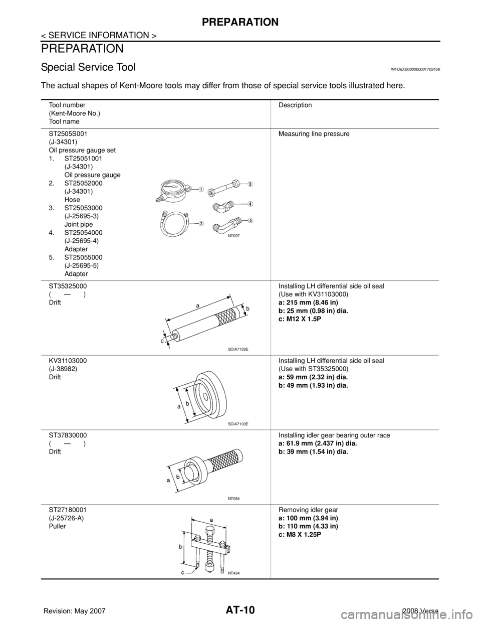
Special Service ToolINFOID:0000000001703156
The actual shapes of Kent-Moore tools may differ from those of special service tools illustrated here.
Tool number
(Kent-Moore No.)
Tool nameDescription
ST2505S001
(J-34301)
Oil pressure gauge set
1. ST25051001
(J-34301)
Oil pressure gauge
2. ST25052000
(J-34301)
Hose
3. ST25053000
(J-25695-3)
Joint pipe
4. ST25054000
(J-25695-4)
Adapter
5. ST25055000
(J-25695-5)
AdapterMeasuring line pressure
ST35325000
( — )
DriftInstalling LH differential side oil seal
(Use with KV31103000)
a: 215 mm (8.46 in)
b: 25 mm (0.98 in) dia.
c: M12 X 1.5P
KV31103000
(J-38982)
DriftInstalling LH differential side oil seal
(Use with ST35325000)
a: 59 mm (2.32 in) dia.
b: 49 mm (1.93 in) dia.
ST37830000
( — )
DriftInstalling idler gear bearing outer race
a: 61.9 mm (2.437 in) dia.
b: 39 mm (1.54 in) dia.
ST27180001
(J-25726-A)
PullerRemoving idler gear
a: 100 mm (3.94 in)
b: 110 mm (4.33 in)
c: M8 X 1.25P
NT097
SCIA7102E
SCIA7103E
NT084
NT424
Page 33 of 2771
A/T CONTROL SYSTEM
AT-21
< SERVICE INFORMATION >
D
E
F
G
H
I
J
K
L
MA
B
AT
N
O
P
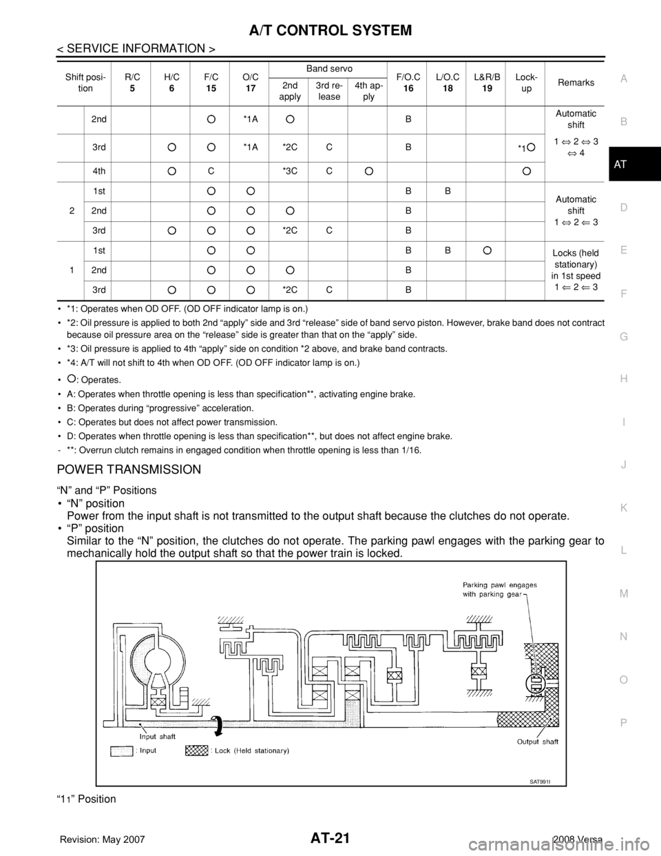
• *1: Operates when OD OFF. (OD OFF indicator lamp is on.)
• *2: Oil pressure is applied to both 2nd “apply” side and 3rd “release” side of band servo piston. However, brake band does not contract
because oil pressure area on the “release” side is greater than that on the “apply” side.
• *3: Oil pressure is applied to 4th “apply” side on condition *2 above, and brake band contracts.
• *4: A/T will not shift to 4th when OD OFF. (OD OFF indicator lamp is on.)
• : Operates.
• A: Operates when throttle opening is less than specification**, activating engine brake.
• B: Operates during “progressive” acceleration.
• C: Operates but does not affect power transmission.
• D: Operates when throttle opening is less than specification**, but does not affect engine brake.
- **: Overrun clutch remains in engaged condition when throttle opening is less than 1/16.
POWER TRANSMISSION
“N” and “P” Positions
• “N” position
Power from the input shaft is not transmitted to the output shaft because the clutches do not operate.
• “P” position
Similar to the “N” position, the clutches do not operate. The parking pawl engages with the parking gear to
mechanically hold the output shaft so that the power train is locked.
“11” Position
2nd *1A BAutomatic
shift
3rd *1A *2C C B
*11 ⇔ 2 ⇔ 3
⇔ 4
4th C *3C C
21stBB
Automatic
shift
1 ⇔ 2 ⇐ 3 2ndB
3rd *2C C B
11stBB
Locks (held
stationary)
in 1st speed
1 ⇐ 2 ⇐ 3 2ndB
3rd *2C C B Shift posi-
tionR/C
5H/C
6F/C
15O/C
17Band servo
F/O.C
16L/O.C
18L&R/B
19Lock-
upRemarks
2nd
apply3rd re-
lease4th ap-
ply
SAT991I
Page 39 of 2771
A/T CONTROL SYSTEM
AT-27
< SERVICE INFORMATION >
D
E
F
G
H
I
J
K
L
MA
B
AT
N
O
P
TCM FunctionINFOID:0000000001703163
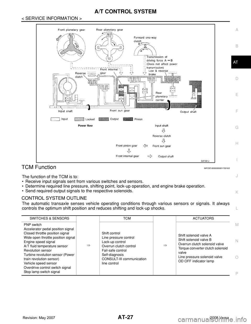
The function of the TCM is to:
• Receive input signals sent from various switches and sensors.
• Determine required line pressure, shifting point, lock-up operation, and engine brake operation.
• Send required output signals to the respective solenoids.
CONTROL SYSTEM OUTLINE
The automatic transaxle senses vehicle operating conditions through various sensors or signals. It always
controls the optimum shift position and reduces shifting and lock-up shocks.
SAT381J
SWITCHES & SENSORS
⇒TCM
⇒ACTUATORS
PNP switch
Accelerator pedal position signal
Closed throttle position signal
Wide open throttle position signal
Engine speed signal
A/T fluid temperature sensor
Revolution sensor
Turbine revolution sensor (Power
train revolution sensor)
Vehicle speed sensor
Overdrive control switch signal
Stop lamp switch signalShift control
Line pressure control
Lock-up control
Overrun clutch control
Fail-safe control
Self-diagnosis
CONSULT-III communication
line controlShift solenoid valve A
Shift solenoid valve B
Overrun clutch solenoid valve
Torque converter clutch solenoid
valve
Line pressure solenoid valve
OD OFF indicator lamp
Page 40 of 2771
AT-28
< SERVICE INFORMATION >
A/T CONTROL SYSTEM
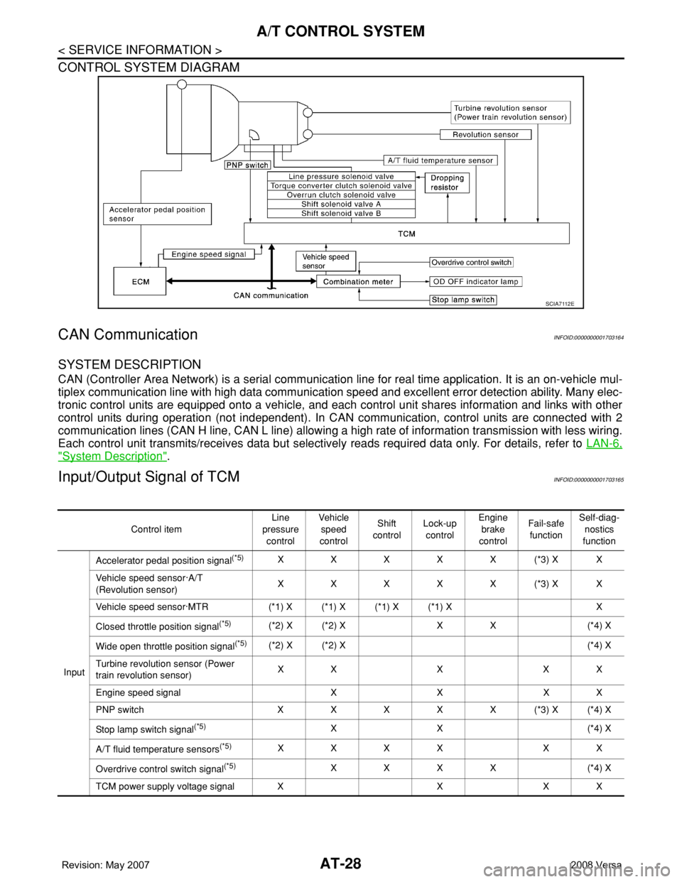
CONTROL SYSTEM DIAGRAM
CAN CommunicationINFOID:0000000001703164
SYSTEM DESCRIPTION
CAN (Controller Area Network) is a serial communication line for real time application. It is an on-vehicle mul-
tiplex communication line with high data communication speed and excellent error detection ability. Many elec-
tronic control units are equipped onto a vehicle, and each control unit shares information and links with other
control units during operation (not independent). In CAN communication, control units are connected with 2
communication lines (CAN H line, CAN L line) allowing a high rate of information transmission with less wiring.
Each control unit transmits/receives data but selectively reads required data only. For details, refer to LAN-6,
"System Description".
Input/Output Signal of TCMINFOID:0000000001703165
SCIA7112E
Control itemLine
pressure
controlVehicle
speed
controlShift
controlLock-up
controlEngine
brake
controlFail-safe
functionSelf-diag-
nostics
function
InputAccelerator pedal position signal
(*5)XXXXX(*3) XX
Vehicle speed sensor·A/T
(Revolution sensor)XXXXX(*3) XX
Vehicle speed sensor·MTR (*1) X (*1) X (*1) X (*1) X X
Closed throttle position signal
(*5)(*2) X (*2) X X X (*4) X
Wide open throttle position signal
(*5)(*2) X (*2) X (*4) X
Turbine revolution sensor (Power
train revolution sensor)XXXXX
Engine speed signal X X X X
PNP switch XXXXX(*3) X(*4) X
Stop lamp switch signal
(*5)XX (*4) X
A/T fluid temperature sensors
(*5)XXXX XX
Overdrive control switch signal
(*5)XXXX (*4) X
TCM power supply voltage signal X X X X