Ps-9 NISSAN TIIDA 2008 Service Repair Manual
[x] Cancel search | Manufacturer: NISSAN, Model Year: 2008, Model line: TIIDA, Model: NISSAN TIIDA 2008Pages: 2771, PDF Size: 60.61 MB
Page 1844 of 2771
FSU-10
< SERVICE INFORMATION >
FRONT SUSPENSION ASSEMBLY
Removal and Installation
INFOID:0000000001703724
REMOVAL
1. Separate intermediate shaft from steering gear pinion shaft. Refer to PS-9, "Removal and Installation".
2. Remove front tires from vehicle using a power tool.
3. Remove wheel sensor from steering knuckle. Refer to BRC-32
.
CAUTION:
Do not pull on wheel sensor harness.
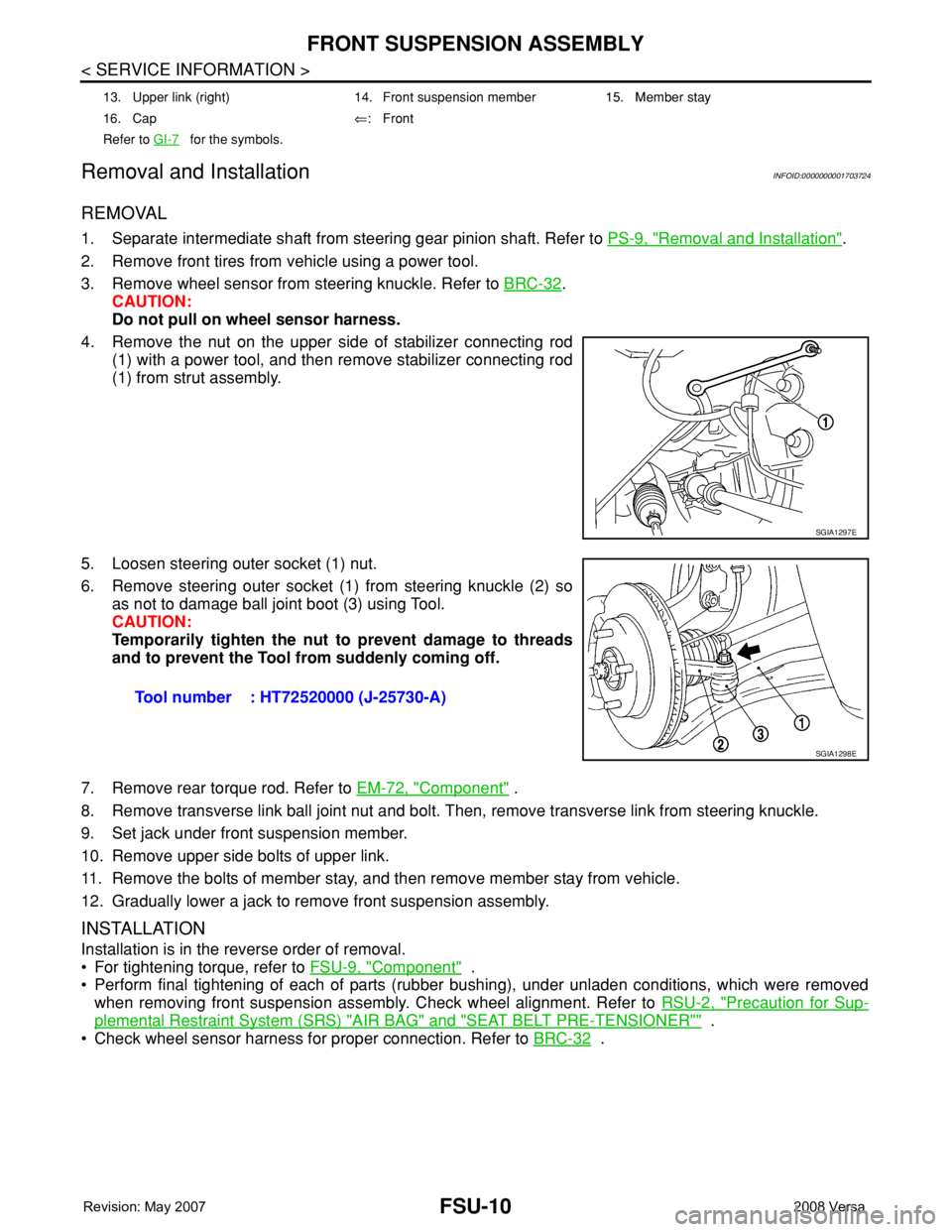
4. Remove the nut on the upper side of stabilizer connecting rod
(1) with a power tool, and then remove stabilizer connecting rod
(1) from strut assembly.
5. Loosen steering outer socket (1) nut.
6. Remove steering outer socket (1) from steering knuckle (2) so
as not to damage ball joint boot (3) using Tool.
CAUTION:
Temporarily tighten the nut to prevent damage to threads
and to prevent the Tool from suddenly coming off.
7. Remove rear torque rod. Refer to EM-72, "
Component" .
8. Remove transverse link ball joint nut and bolt. Then, remove transverse link from steering knuckle.
9. Set jack under front suspension member.
10. Remove upper side bolts of upper link.
11. Remove the bolts of member stay, and then remove member stay from vehicle.
12. Gradually lower a jack to remove front suspension assembly.
INSTALLATION
Installation is in the reverse order of removal.
• For tightening torque, refer to FSU-9, "
Component" .
• Perform final tightening of each of parts (rubber bushing), under unladen conditions, which were removed
when removing front suspension assembly. Check wheel alignment. Refer to RSU-2, "
Precaution for Sup-
plemental Restraint System (SRS) "AIR BAG" and "SEAT BELT PRE-TENSIONER"" .
• Check wheel sensor harness for proper connection. Refer to BRC-32
.
13. Upper link (right) 14. Front suspension member 15. Member stay
16. Cap⇐:Front
Refer to GI-7
for the symbols.
SGIA1297E
Tool number : HT72520000 (J-25730-A)
SGIA1298E
Page 1849 of 2771
STABILIZER BAR
FSU-15
< SERVICE INFORMATION >
C
D
F
G
H
I
J
K
L
MA
B
FSU
N
O
P
STABILIZER BAR
Removal and InstallationINFOID:0000000001703728
REMOVAL
1. Separate intermediate shaft from steering gear pinion shaft. Refer to PS-9, "Removal and Installation" .
2. Remove front tires using power tool.
3. Remove the nut on the lower side of stabilizer connecting rod using power tool, and then remove stabilizer
connecting rod from stabilizer bar.
4. If necessary remove stabilize connecting rod upper nut using power tool. Separate stabilizer connecting
rod and strut.
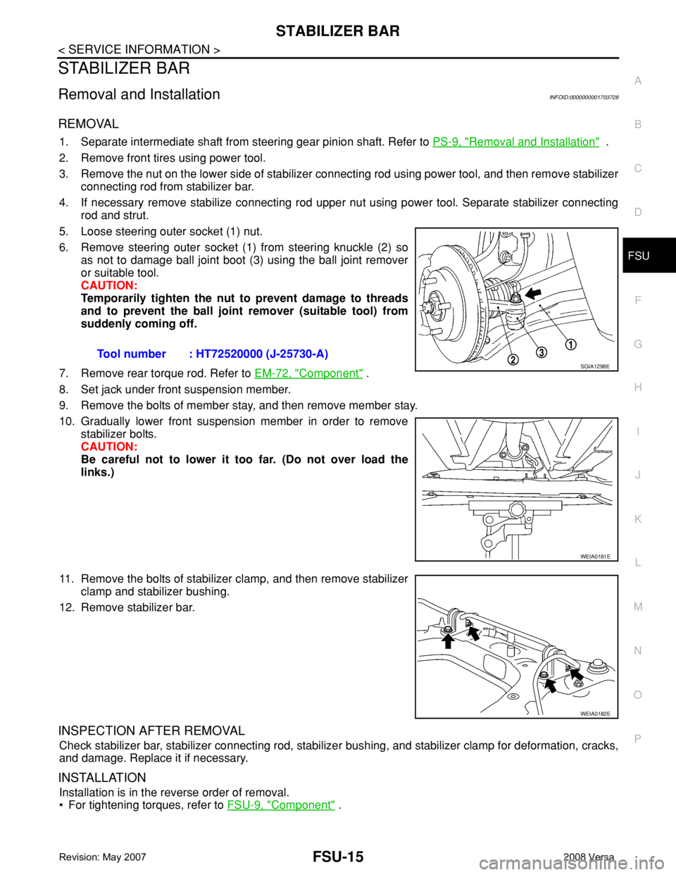
5. Loose steering outer socket (1) nut.
6. Remove steering outer socket (1) from steering knuckle (2) so
as not to damage ball joint boot (3) using the ball joint remover
or suitable tool.
CAUTION:
Temporarily tighten the nut to prevent damage to threads
and to prevent the ball joint remover (suitable tool) from
suddenly coming off.
7. Remove rear torque rod. Refer to EM-72, "
Component" .
8. Set jack under front suspension member.
9. Remove the bolts of member stay, and then remove member stay.
10. Gradually lower front suspension member in order to remove
stabilizer bolts.
CAUTION:
Be careful not to lower it too far. (Do not over load the
links.)
11. Remove the bolts of stabilizer clamp, and then remove stabilizer
clamp and stabilizer bushing.
12. Remove stabilizer bar.
INSPECTION AFTER REMOVAL
Check stabilizer bar, stabilizer connecting rod, stabilizer bushing, and stabilizer clamp for deformation, cracks,
and damage. Replace it if necessary.
INSTALLATION
Installation is in the reverse order of removal.
• For tightening torques, refer to FSU-9, "
Component" . Tool number : HT72520000 (J-25730-A)
SGIA1298E
WEIA0181E
WEIA0182E
Page 2027 of 2771
![NISSAN TIIDA 2008 Service Repair Manual LAN-36
< COMPONENT DIAGNOSIS >[CAN]
EPS BRANCH LINE CIRCUIT
EPS BRANCH LINE CIRCUIT
Diagnosis ProcedureINFOID:0000000001711232
INSPECTION PROCEDURE
1.CHECK CONNECTOR
1. Turn the ignition switch OFF.
2](/img/5/57399/w960_57399-2026.png "NISSAN TIIDA 2008 Service Repair Manual LAN-36
< COMPONENT DIAGNOSIS >[CAN]
EPS BRANCH LINE CIRCUIT
EPS BRANCH LINE CIRCUIT
Diagnosis ProcedureINFOID:0000000001711232
INSPECTION PROCEDURE
1.CHECK CONNECTOR
1. Turn the ignition switch OFF.
2")
LAN-36
< COMPONENT DIAGNOSIS >[CAN]
EPS BRANCH LINE CIRCUIT
EPS BRANCH LINE CIRCUIT
Diagnosis ProcedureINFOID:0000000001711232
INSPECTION PROCEDURE
1.CHECK CONNECTOR
1. Turn the ignition switch OFF.
2. Disconnect the battery cable from the negative terminal.
3. Check the terminals and connectors of the EPS control unit for damage, bend and loose connection (unit
side and connector side).
Is the inspection result normal?
YES >> GO TO 2.
NO >> Repair the terminal and connector.
2.CHECK HARNESS FOR OPEN CIRCUIT
1. Disconnect the connector of EPS control unit.
2. Check the resistance between the EPS control unit harness connector terminals.
Is the measurement value within the specification?
YES >> GO TO 3.
NO >> Repair the EPS control unit branch line.
3.CHECK POWER SUPPLY AND GROUND CIRCUIT
Check the power supply and the ground circuit of the EPS control unit. Refer to STC-14, "
DTC C1601 BAT-
TERY VOLT".
Is the inspection result normal?
YES (Present error)>>Replace the EPS control unit. Refer to PS-9, "Removal and Installation".
YES (Past error)>>Error was detected in the EPS control unit branch line.
NO >> Repair the power supply and the ground circuit.
EPS control unit harness connector
Resistance (Ω)
Connector No. Terminal No.
M53 9 16 Approx. 54 – 66
Page 2038 of 2771
![NISSAN TIIDA 2008 Service Repair Manual EPS BRANCH LINE CIRCUIT
LAN-47
< COMPONENT DIAGNOSIS >[CAN SYSTEM (TYPE 1)]
C
D
E
F
G
H
I
J
L
MA
B
LAN
N
O
P
EPS BRANCH LINE CIRCUIT
Diagnosis ProcedureINFOID:0000000001711348
INSPECTION PROCEDURE
1.C](/img/5/57399/w960_57399-2037.png "NISSAN TIIDA 2008 Service Repair Manual EPS BRANCH LINE CIRCUIT
LAN-47
< COMPONENT DIAGNOSIS >[CAN SYSTEM (TYPE 1)]
C
D
E
F
G
H
I
J
L
MA
B
LAN
N
O
P
EPS BRANCH LINE CIRCUIT
Diagnosis ProcedureINFOID:0000000001711348
INSPECTION PROCEDURE
1.C")
EPS BRANCH LINE CIRCUIT
LAN-47
< COMPONENT DIAGNOSIS >[CAN SYSTEM (TYPE 1)]
C
D
E
F
G
H
I
J
L
MA
B
LAN
N
O
P
EPS BRANCH LINE CIRCUIT
Diagnosis ProcedureINFOID:0000000001711348
INSPECTION PROCEDURE
1.CHECK CONNECTOR
1. Turn the ignition switch OFF.
2. Disconnect the battery cable from the negative terminal.
3. Check the terminals and connectors of the EPS control unit for damage, bend and loose connection (unit
side and connector side).
Is the inspection result normal?
YES >> GO TO 2.
NO >> Repair the terminal and connector.
2.CHECK HARNESS FOR OPEN CIRCUIT
1. Disconnect the connector of EPS control unit.
2. Check the resistance between the EPS control unit harness connector terminals.
Is the measurement value within the specification?
YES >> GO TO 3.
NO >> Repair the EPS control unit branch line.
3.CHECK POWER SUPPLY AND GROUND CIRCUIT
Check the power supply and the ground circuit of the EPS control unit. Refer to STC-14, "
DTC C1601 BAT-
TERY VOLT".
Is the inspection result normal?
YES (Present error)>>Replace the EPS control unit. Refer to PS-9, "Removal and Installation".
YES (Past error)>>Error was detected in the EPS control unit branch line.
NO >> Repair the power supply and the ground circuit.
EPS control unit harness connector
Resistance (Ω)
Connector No. Terminal No.
M53 9 16 Approx. 54 – 66
Page 2046 of 2771
![NISSAN TIIDA 2008 Service Repair Manual EPS BRANCH LINE CIRCUIT
LAN-55
< COMPONENT DIAGNOSIS >[CAN SYSTEM (TYPE 2)]
C
D
E
F
G
H
I
J
L
MA
B
LAN
N
O
P
EPS BRANCH LINE CIRCUIT
Diagnosis ProcedureINFOID:0000000001711368
INSPECTION PROCEDURE
1.C](/img/5/57399/w960_57399-2045.png "NISSAN TIIDA 2008 Service Repair Manual EPS BRANCH LINE CIRCUIT
LAN-55
< COMPONENT DIAGNOSIS >[CAN SYSTEM (TYPE 2)]
C
D
E
F
G
H
I
J
L
MA
B
LAN
N
O
P
EPS BRANCH LINE CIRCUIT
Diagnosis ProcedureINFOID:0000000001711368
INSPECTION PROCEDURE
1.C")
EPS BRANCH LINE CIRCUIT
LAN-55
< COMPONENT DIAGNOSIS >[CAN SYSTEM (TYPE 2)]
C
D
E
F
G
H
I
J
L
MA
B
LAN
N
O
P
EPS BRANCH LINE CIRCUIT
Diagnosis ProcedureINFOID:0000000001711368
INSPECTION PROCEDURE
1.CHECK CONNECTOR
1. Turn the ignition switch OFF.
2. Disconnect the battery cable from the negative terminal.
3. Check the terminals and connectors of the EPS control unit for damage, bend and loose connection (unit
side and connector side).
Is the inspection result normal?
YES >> GO TO 2.
NO >> Repair the terminal and connector.
2.CHECK HARNESS FOR OPEN CIRCUIT
1. Disconnect the connector of EPS control unit.
2. Check the resistance between the EPS control unit harness connector terminals.
Is the measurement value within the specification?
YES >> GO TO 3.
NO >> Repair the EPS control unit branch line.
3.CHECK POWER SUPPLY AND GROUND CIRCUIT
Check the power supply and the ground circuit of the EPS control unit. Refer to STC-14, "
DTC C1601 BAT-
TERY VOLT".
Is the inspection result normal?
YES (Present error)>>Replace the EPS control unit. Refer to PS-9, "Removal and Installation".
YES (Past error)>>Error was detected in the EPS control unit branch line.
NO >> Repair the power supply and the ground circuit.
EPS control unit harness connector
Resistance (Ω)
Connector No. Terminal No.
M53 9 16 Approx. 54 – 66
Page 2056 of 2771
![NISSAN TIIDA 2008 Service Repair Manual EPS BRANCH LINE CIRCUIT
LAN-65
< COMPONENT DIAGNOSIS >[CAN SYSTEM (TYPE 3)]
C
D
E
F
G
H
I
J
L
MA
B
LAN
N
O
P
EPS BRANCH LINE CIRCUIT
Diagnosis ProcedureINFOID:0000000001711388
INSPECTION PROCEDURE
1.C](/img/5/57399/w960_57399-2055.png "NISSAN TIIDA 2008 Service Repair Manual EPS BRANCH LINE CIRCUIT
LAN-65
< COMPONENT DIAGNOSIS >[CAN SYSTEM (TYPE 3)]
C
D
E
F
G
H
I
J
L
MA
B
LAN
N
O
P
EPS BRANCH LINE CIRCUIT
Diagnosis ProcedureINFOID:0000000001711388
INSPECTION PROCEDURE
1.C")
EPS BRANCH LINE CIRCUIT
LAN-65
< COMPONENT DIAGNOSIS >[CAN SYSTEM (TYPE 3)]
C
D
E
F
G
H
I
J
L
MA
B
LAN
N
O
P
EPS BRANCH LINE CIRCUIT
Diagnosis ProcedureINFOID:0000000001711388
INSPECTION PROCEDURE
1.CHECK CONNECTOR
1. Turn the ignition switch OFF.
2. Disconnect the battery cable from the negative terminal.
3. Check the terminals and connectors of the EPS control unit for damage, bend and loose connection (unit
side and connector side).
Is the inspection result normal?
YES >> GO TO 2.
NO >> Repair the terminal and connector.
2.CHECK HARNESS FOR OPEN CIRCUIT
1. Disconnect the connector of EPS control unit.
2. Check the resistance between the EPS control unit harness connector terminals.
Is the measurement value within the specification?
YES >> GO TO 3.
NO >> Repair the EPS control unit branch line.
3.CHECK POWER SUPPLY AND GROUND CIRCUIT
Check the power supply and the ground circuit of the EPS control unit. Refer to STC-14, "
DTC C1601 BAT-
TERY VOLT".
Is the inspection result normal?
YES (Present error)>>Replace the EPS control unit. Refer to PS-9, "Removal and Installation".
YES (Past error)>>Error was detected in the EPS control unit branch line.
NO >> Repair the power supply and the ground circuit.
EPS control unit harness connector
Resistance (Ω)
Connector No. Terminal No.
M53 9 16 Approx. 54 – 66
Page 2066 of 2771
![NISSAN TIIDA 2008 Service Repair Manual EPS BRANCH LINE CIRCUIT
LAN-75
< COMPONENT DIAGNOSIS >[CAN SYSTEM (TYPE 4)]
C
D
E
F
G
H
I
J
L
MA
B
LAN
N
O
P
EPS BRANCH LINE CIRCUIT
Diagnosis ProcedureINFOID:0000000001711408
INSPECTION PROCEDURE
1.C](/img/5/57399/w960_57399-2065.png "NISSAN TIIDA 2008 Service Repair Manual EPS BRANCH LINE CIRCUIT
LAN-75
< COMPONENT DIAGNOSIS >[CAN SYSTEM (TYPE 4)]
C
D
E
F
G
H
I
J
L
MA
B
LAN
N
O
P
EPS BRANCH LINE CIRCUIT
Diagnosis ProcedureINFOID:0000000001711408
INSPECTION PROCEDURE
1.C")
EPS BRANCH LINE CIRCUIT
LAN-75
< COMPONENT DIAGNOSIS >[CAN SYSTEM (TYPE 4)]
C
D
E
F
G
H
I
J
L
MA
B
LAN
N
O
P
EPS BRANCH LINE CIRCUIT
Diagnosis ProcedureINFOID:0000000001711408
INSPECTION PROCEDURE
1.CHECK CONNECTOR
1. Turn the ignition switch OFF.
2. Disconnect the battery cable from the negative terminal.
3. Check the terminals and connectors of the EPS control unit for damage, bend and loose connection (unit
side and connector side).
Is the inspection result normal?
YES >> GO TO 2.
NO >> Repair the terminal and connector.
2.CHECK HARNESS FOR OPEN CIRCUIT
1. Disconnect the connector of EPS control unit.
2. Check the resistance between the EPS control unit harness connector terminals.
Is the measurement value within the specification?
YES >> GO TO 3.
NO >> Repair the EPS control unit branch line.
3.CHECK POWER SUPPLY AND GROUND CIRCUIT
Check the power supply and the ground circuit of the EPS control unit. Refer to STC-14, "
DTC C1601 BAT-
TERY VOLT".
Is the inspection result normal?
YES (Present error)>>Replace the EPS control unit. Refer to PS-9, "Removal and Installation".
YES (Past error)>>Error was detected in the EPS control unit branch line.
NO >> Repair the power supply and the ground circuit.
EPS control unit harness connector
Resistance (Ω)
Connector No. Terminal No.
M53 9 16 Approx. 54 – 66
Page 2077 of 2771
![NISSAN TIIDA 2008 Service Repair Manual LAN-86
< COMPONENT DIAGNOSIS >[CAN SYSTEM (TYPE 5)]
EPS BRANCH LINE CIRCUIT
EPS BRANCH LINE CIRCUIT
Diagnosis ProcedureINFOID:0000000001711428
INSPECTION PROCEDURE
1.CHECK CONNECTOR
1. Turn the igniti](/img/5/57399/w960_57399-2076.png "NISSAN TIIDA 2008 Service Repair Manual LAN-86
< COMPONENT DIAGNOSIS >[CAN SYSTEM (TYPE 5)]
EPS BRANCH LINE CIRCUIT
EPS BRANCH LINE CIRCUIT
Diagnosis ProcedureINFOID:0000000001711428
INSPECTION PROCEDURE
1.CHECK CONNECTOR
1. Turn the igniti")
LAN-86
< COMPONENT DIAGNOSIS >[CAN SYSTEM (TYPE 5)]
EPS BRANCH LINE CIRCUIT
EPS BRANCH LINE CIRCUIT
Diagnosis ProcedureINFOID:0000000001711428
INSPECTION PROCEDURE
1.CHECK CONNECTOR
1. Turn the ignition switch OFF.
2. Disconnect the battery cable from the negative terminal.
3. Check the terminals and connectors of the EPS control unit for damage, bend and loose connection (unit
side and connector side).
Is the inspection result normal?
YES >> GO TO 2.
NO >> Repair the terminal and connector.
2.CHECK HARNESS FOR OPEN CIRCUIT
1. Disconnect the connector of EPS control unit.
2. Check the resistance between the EPS control unit harness connector terminals.
Is the measurement value within the specification?
YES >> GO TO 3.
NO >> Repair the EPS control unit branch line.
3.CHECK POWER SUPPLY AND GROUND CIRCUIT
Check the power supply and the ground circuit of the EPS control unit. Refer to STC-14, "
DTC C1601 BAT-
TERY VOLT".
Is the inspection result normal?
YES (Present error)>>Replace the EPS control unit. Refer to PS-9, "Removal and Installation".
YES (Past error)>>Error was detected in the EPS control unit branch line.
NO >> Repair the power supply and the ground circuit.
EPS control unit harness connector
Resistance (Ω)
Connector No. Terminal No.
M53 9 16 Approx. 54 – 66
Page 2087 of 2771
![NISSAN TIIDA 2008 Service Repair Manual LAN-96
< COMPONENT DIAGNOSIS >[CAN SYSTEM (TYPE 6)]
EPS BRANCH LINE CIRCUIT
EPS BRANCH LINE CIRCUIT
Diagnosis ProcedureINFOID:0000000001711448
INSPECTION PROCEDURE
1.CHECK CONNECTOR
1. Turn the igniti](/img/5/57399/w960_57399-2086.png "NISSAN TIIDA 2008 Service Repair Manual LAN-96
< COMPONENT DIAGNOSIS >[CAN SYSTEM (TYPE 6)]
EPS BRANCH LINE CIRCUIT
EPS BRANCH LINE CIRCUIT
Diagnosis ProcedureINFOID:0000000001711448
INSPECTION PROCEDURE
1.CHECK CONNECTOR
1. Turn the igniti")
LAN-96
< COMPONENT DIAGNOSIS >[CAN SYSTEM (TYPE 6)]
EPS BRANCH LINE CIRCUIT
EPS BRANCH LINE CIRCUIT
Diagnosis ProcedureINFOID:0000000001711448
INSPECTION PROCEDURE
1.CHECK CONNECTOR
1. Turn the ignition switch OFF.
2. Disconnect the battery cable from the negative terminal.
3. Check the terminals and connectors of the EPS control unit for damage, bend and loose connection (unit
side and connector side).
Is the inspection result normal?
YES >> GO TO 2.
NO >> Repair the terminal and connector.
2.CHECK HARNESS FOR OPEN CIRCUIT
1. Disconnect the connector of EPS control unit.
2. Check the resistance between the EPS control unit harness connector terminals.
Is the measurement value within the specification?
YES >> GO TO 3.
NO >> Repair the EPS control unit branch line.
3.CHECK POWER SUPPLY AND GROUND CIRCUIT
Check the power supply and the ground circuit of the EPS control unit. Refer to STC-14, "
DTC C1601 BAT-
TERY VOLT".
Is the inspection result normal?
YES (Present error)>>Replace the EPS control unit. Refer to PS-9, "Removal and Installation".
YES (Past error)>>Error was detected in the EPS control unit branch line.
NO >> Repair the power supply and the ground circuit.
EPS control unit harness connector
Resistance (Ω)
Connector No. Terminal No.
M53 9 16 Approx. 54 – 66
Page 2098 of 2771
![NISSAN TIIDA 2008 Service Repair Manual EPS BRANCH LINE CIRCUIT
LAN-107
< COMPONENT DIAGNOSIS >[CAN SYSTEM (TYPE 7)]
C
D
E
F
G
H
I
J
L
MA
B
LAN
N
O
P
EPS BRANCH LINE CIRCUIT
Diagnosis ProcedureINFOID:0000000001711468
INSPECTION PROCEDURE
1.](/img/5/57399/w960_57399-2097.png "NISSAN TIIDA 2008 Service Repair Manual EPS BRANCH LINE CIRCUIT
LAN-107
< COMPONENT DIAGNOSIS >[CAN SYSTEM (TYPE 7)]
C
D
E
F
G
H
I
J
L
MA
B
LAN
N
O
P
EPS BRANCH LINE CIRCUIT
Diagnosis ProcedureINFOID:0000000001711468
INSPECTION PROCEDURE
1.")
EPS BRANCH LINE CIRCUIT
LAN-107
< COMPONENT DIAGNOSIS >[CAN SYSTEM (TYPE 7)]
C
D
E
F
G
H
I
J
L
MA
B
LAN
N
O
P
EPS BRANCH LINE CIRCUIT
Diagnosis ProcedureINFOID:0000000001711468
INSPECTION PROCEDURE
1.CHECK CONNECTOR
1. Turn the ignition switch OFF.
2. Disconnect the battery cable from the negative terminal.
3. Check the terminals and connectors of the EPS control unit for damage, bend and loose connection (unit
side and connector side).
Is the inspection result normal?
YES >> GO TO 2.
NO >> Repair the terminal and connector.
2.CHECK HARNESS FOR OPEN CIRCUIT
1. Disconnect the connector of EPS control unit.
2. Check the resistance between the EPS control unit harness connector terminals.
Is the measurement value within the specification?
YES >> GO TO 3.
NO >> Repair the EPS control unit branch line.
3.CHECK POWER SUPPLY AND GROUND CIRCUIT
Check the power supply and the ground circuit of the EPS control unit. Refer to STC-14, "
DTC C1601 BAT-
TERY VOLT".
Is the inspection result normal?
YES (Present error)>>Replace the EPS control unit. Refer to PS-9, "Removal and Installation".
YES (Past error)>>Error was detected in the EPS control unit branch line.
NO >> Repair the power supply and the ground circuit.
EPS control unit harness connector
Resistance (Ω)
Connector No. Terminal No.
M53 9 16 Approx. 54 – 66