Ps-9 NISSAN TIIDA 2008 Service User Guide
[x] Cancel search | Manufacturer: NISSAN, Model Year: 2008, Model line: TIIDA, Model: NISSAN TIIDA 2008Pages: 2771, PDF Size: 60.61 MB
Page 2108 of 2771
![NISSAN TIIDA 2008 Service User Guide EPS BRANCH LINE CIRCUIT
LAN-117
< COMPONENT DIAGNOSIS >[CAN SYSTEM (TYPE 8)]
C
D
E
F
G
H
I
J
L
MA
B
LAN
N
O
P
EPS BRANCH LINE CIRCUIT
Diagnosis ProcedureINFOID:0000000001711488
INSPECTION PROCEDURE
1.](/img/5/57399/w960_57399-2107.png "NISSAN TIIDA 2008 Service User Guide EPS BRANCH LINE CIRCUIT
LAN-117
< COMPONENT DIAGNOSIS >[CAN SYSTEM (TYPE 8)]
C
D
E
F
G
H
I
J
L
MA
B
LAN
N
O
P
EPS BRANCH LINE CIRCUIT
Diagnosis ProcedureINFOID:0000000001711488
INSPECTION PROCEDURE
1.")
EPS BRANCH LINE CIRCUIT
LAN-117
< COMPONENT DIAGNOSIS >[CAN SYSTEM (TYPE 8)]
C
D
E
F
G
H
I
J
L
MA
B
LAN
N
O
P
EPS BRANCH LINE CIRCUIT
Diagnosis ProcedureINFOID:0000000001711488
INSPECTION PROCEDURE
1.CHECK CONNECTOR
1. Turn the ignition switch OFF.
2. Disconnect the battery cable from the negative terminal.
3. Check the terminals and connectors of the EPS control unit for damage, bend and loose connection (unit
side and connector side).
Is the inspection result normal?
YES >> GO TO 2.
NO >> Repair the terminal and connector.
2.CHECK HARNESS FOR OPEN CIRCUIT
1. Disconnect the connector of EPS control unit.
2. Check the resistance between the EPS control unit harness connector terminals.
Is the measurement value within the specification?
YES >> GO TO 3.
NO >> Repair the EPS control unit branch line.
3.CHECK POWER SUPPLY AND GROUND CIRCUIT
Check the power supply and the ground circuit of the EPS control unit. Refer to STC-14, "
DTC C1601 BAT-
TERY VOLT".
Is the inspection result normal?
YES (Present error)>>Replace the EPS control unit. Refer to PS-9, "Removal and Installation".
YES (Past error)>>Error was detected in the EPS control unit branch line.
NO >> Repair the power supply and the ground circuit.
EPS control unit harness connector
Resistance (Ω)
Connector No. Terminal No.
M53 9 16 Approx. 54 – 66
Page 2119 of 2771
![NISSAN TIIDA 2008 Service User Guide LAN-128
< COMPONENT DIAGNOSIS >[CAN SYSTEM (TYPE 9)]
EPS BRANCH LINE CIRCUIT
EPS BRANCH LINE CIRCUIT
Diagnosis ProcedureINFOID:0000000001711508
INSPECTION PROCEDURE
1.CHECK CONNECTOR
1. Turn the ignit](/img/5/57399/w960_57399-2118.png "NISSAN TIIDA 2008 Service User Guide LAN-128
< COMPONENT DIAGNOSIS >[CAN SYSTEM (TYPE 9)]
EPS BRANCH LINE CIRCUIT
EPS BRANCH LINE CIRCUIT
Diagnosis ProcedureINFOID:0000000001711508
INSPECTION PROCEDURE
1.CHECK CONNECTOR
1. Turn the ignit")
LAN-128
< COMPONENT DIAGNOSIS >[CAN SYSTEM (TYPE 9)]
EPS BRANCH LINE CIRCUIT
EPS BRANCH LINE CIRCUIT
Diagnosis ProcedureINFOID:0000000001711508
INSPECTION PROCEDURE
1.CHECK CONNECTOR
1. Turn the ignition switch OFF.
2. Disconnect the battery cable from the negative terminal.
3. Check the terminals and connectors of the EPS control unit for damage, bend and loose connection (unit
side and connector side).
Is the inspection result normal?
YES >> GO TO 2.
NO >> Repair the terminal and connector.
2.CHECK HARNESS FOR OPEN CIRCUIT
1. Disconnect the connector of EPS control unit.
2. Check the resistance between the EPS control unit harness connector terminals.
Is the measurement value within the specification?
YES >> GO TO 3.
NO >> Repair the EPS control unit branch line.
3.CHECK POWER SUPPLY AND GROUND CIRCUIT
Check the power supply and the ground circuit of the EPS control unit. Refer to STC-14, "
DTC C1601 BAT-
TERY VOLT".
Is the inspection result normal?
YES (Present error)>>Replace the EPS control unit. Refer to PS-9, "Removal and Installation".
YES (Past error)>>Error was detected in the EPS control unit branch line.
NO >> Repair the power supply and the ground circuit.
EPS control unit harness connector
Resistance (Ω)
Connector No. Terminal No.
M53 9 16 Approx. 54 – 66
Page 2130 of 2771
![NISSAN TIIDA 2008 Service User Guide EPS BRANCH LINE CIRCUIT
LAN-139
< COMPONENT DIAGNOSIS >[CAN SYSTEM (TYPE 10)]
C
D
E
F
G
H
I
J
L
MA
B
LAN
N
O
P
EPS BRANCH LINE CIRCUIT
Diagnosis ProcedureINFOID:0000000001711528
INSPECTION PROCEDURE
1](/img/5/57399/w960_57399-2129.png "NISSAN TIIDA 2008 Service User Guide EPS BRANCH LINE CIRCUIT
LAN-139
< COMPONENT DIAGNOSIS >[CAN SYSTEM (TYPE 10)]
C
D
E
F
G
H
I
J
L
MA
B
LAN
N
O
P
EPS BRANCH LINE CIRCUIT
Diagnosis ProcedureINFOID:0000000001711528
INSPECTION PROCEDURE
1")
EPS BRANCH LINE CIRCUIT
LAN-139
< COMPONENT DIAGNOSIS >[CAN SYSTEM (TYPE 10)]
C
D
E
F
G
H
I
J
L
MA
B
LAN
N
O
P
EPS BRANCH LINE CIRCUIT
Diagnosis ProcedureINFOID:0000000001711528
INSPECTION PROCEDURE
1.CHECK CONNECTOR
1. Turn the ignition switch OFF.
2. Disconnect the battery cable from the negative terminal.
3. Check the terminals and connectors of the EPS control unit for damage, bend and loose connection (unit
side and connector side).
Is the inspection result normal?
YES >> GO TO 2.
NO >> Repair the terminal and connector.
2.CHECK HARNESS FOR OPEN CIRCUIT
1. Disconnect the connector of EPS control unit.
2. Check the resistance between the EPS control unit harness connector terminals.
Is the measurement value within the specification?
YES >> GO TO 3.
NO >> Repair the EPS control unit branch line.
3.CHECK POWER SUPPLY AND GROUND CIRCUIT
Check the power supply and the ground circuit of the EPS control unit. Refer to STC-14, "
DTC C1601 BAT-
TERY VOLT".
Is the inspection result normal?
YES (Present error)>>Replace the EPS control unit. Refer to PS-9, "Removal and Installation".
YES (Past error)>>Error was detected in the EPS control unit branch line.
NO >> Repair the power supply and the ground circuit.
EPS control unit harness connector
Resistance (Ω)
Connector No. Terminal No.
M53 9 16 Approx. 54 – 66
Page 2397 of 2771
A/C UNIT ASSEMBLY
MTC-59
< SERVICE INFORMATION >
C
D
E
F
G
H
I
K
L
MA
B
MTC
N
O
P
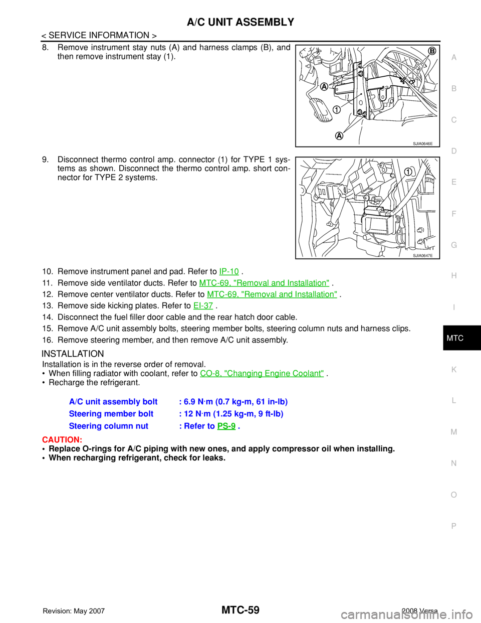
8. Remove instrument stay nuts (A) and harness clamps (B), and
then remove instrument stay (1).
9. Disconnect thermo control amp. connector (1) for TYPE 1 sys-
tems as shown. Disconnect the thermo control amp. short con-
nector for TYPE 2 systems.
10. Remove instrument panel and pad. Refer to IP-10
.
11. Remove side ventilator ducts. Refer to MTC-69, "
Removal and Installation" .
12. Remove center ventilator ducts. Refer to MTC-69, "
Removal and Installation" .
13. Remove side kicking plates. Refer to EI-37
.
14. Disconnect the fuel filler door cable and the rear hatch door cable.
15. Remove A/C unit assembly bolts, steering member bolts, steering column nuts and harness clips.
16. Remove steering member, and then remove A/C unit assembly.
INSTALLATION
Installation is in the reverse order of removal.
• When filling radiator with coolant, refer to CO-8, "
Changing Engine Coolant" .
• Recharge the refrigerant.
CAUTION:
• Replace O-rings for A/C piping with new ones, and apply compressor oil when installing.
• When recharging refrigerant, check for leaks.
SJIA0646E
SJIA0647E
A/C unit assembly bolt : 6.9 N·m (0.7 kg-m, 61 in-lb)
Steering member bolt : 12 N·m (1.25 kg-m, 9 ft-lb)
Steering column nut : Refer to PS-9
.
Page 2511 of 2771
NOISE, VIBRATION AND HARSHNESS (NVH) TROUBLESHOOTING
PS-5
< SERVICE INFORMATION >
C
D
E
F
H
I
J
K
L
MA
B
PS
N
O
P
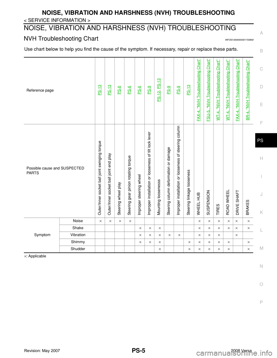
NOISE, VIBRATION AND HARSHNESS (NVH) TROUBLESHOOTING
NVH Troubleshooting ChartINFOID:0000000001703858
Use chart below to help you find the cause of the symptom. If necessary, repair or replace these parts.
×: ApplicableReference page
PS-13PS-13PS-6PS-6PS-6PS-9
PS-12
, PS-13PS-9PS-9PS-13
FAX-4, "
NVH Troubleshooting Chart
"
FSU-5, "
NVH Troubleshooting Chart
"
WT-4, "
NVH Troubleshooting Chart
"
WT-4, "
NVH Troubleshooting Chart
"
FAX-4, "
NVH Troubleshooting Chart
"
BR-4, "
NVH Troubleshooting Chart
"
Possible cause and SUSPECTED
PA R T S
Outer/Inner socket ball joint swinging torque
Outer/Inner socket ball joint end play
Steering wheel play
Steering gear pinion rotating torque
Improper steering wheel
Improper installation or looseness of tilt lock lever
Mounting loosenesss
Steering column deformation or damage
Improper installation or looseness of steering column
Steering linkage looseness
WHEEL HUB
SUSPENSION
TIRES
ROAD WHEEL
DRIVE SHAFT
BRAKES
SymptomNoise××× × ××××× ×
Shake××× ××××× ×
Vibration××××× ××× ×
Shimmy××× × ×××× ×
Shudder× × ×××× ×
Page 2515 of 2771
STEERING COLUMN
PS-9
< SERVICE INFORMATION >
C
D
E
F
H
I
J
K
L
MA
B
PS
N
O
P
STEERING COLUMN
Removal and InstallationINFOID:0000000001703861
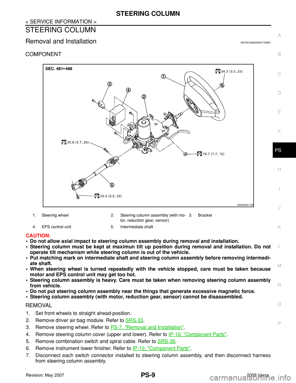
COMPONENT
CAUTION:
• Do not allow axial impact to steering column assembly during removal and installation.
• Steering column must be kept at maximun tilt up position during removal and installation. Do not
operate tilt mechanism while steering column is out of the vehicle.
• Put matching mark on intermediate shaft and steering column assembly before removing intermedi-
ate shaft.
• When steering wheel is turned repeatedly with the vehicle stopped, care must be taken because
motor and EPS control unit may get too hot.
• Steering column assembly is heavy. Care must be taken when removing steering column assembly
from vehicle.
• Do not put steering column assembly near the things that generate excessive magnetic force.
• Steering column assembly (with motor, reduction gear, sensor) cannot be disassembled.
REMOVAL
1. Set front wheels to straight ahead-position.
2. Remove driver air bag module. Refer to SRS-33
.
3. Remove steering wheel. Refer to PS-7, "
Removal and Installation".
4. Remove steering column cover (upper and lower). Refer to IP-10, "
Component Parts".
5. Remove combination switch and spiral cable. Refer to SRS-36
.
6. Remove instrument lower finisher. Refer to IP-10, "
Component Parts".
7. Disconnect each switch connector installed to steering column assembly, and then disconnect harness
from steering column assembly.
1. Steering wheel 2. Steering column assembly (with mo-
tor, reduction gear, sensor)3. Bracket
4. EPS control unit 5. Intermediate shaft
AWGIA0017GB
Page 2699 of 2771
![NISSAN TIIDA 2008 Service User Guide STC-16
< SERVICE INFORMATION >[EPS]
TROUBLE DIAGNOSIS FOR SYSTEM
3. Check continuity between EPS control unit harness connector
(A) M53 terminals 4, 5, 6, 7 and torque sensor harness connec-
tor (B) M](/img/5/57399/w960_57399-2698.png "NISSAN TIIDA 2008 Service User Guide STC-16
< SERVICE INFORMATION >[EPS]
TROUBLE DIAGNOSIS FOR SYSTEM
3. Check continuity between EPS control unit harness connector
(A) M53 terminals 4, 5, 6, 7 and torque sensor harness connec-
tor (B) M")
STC-16
< SERVICE INFORMATION >[EPS]
TROUBLE DIAGNOSIS FOR SYSTEM
3. Check continuity between EPS control unit harness connector
(A) M53 terminals 4, 5, 6, 7 and torque sensor harness connec-
tor (B) M63 terminals 1, 2, 3, 4.
Also check harness for short to ground and short to power.
4. Connect EPS control unit harness connector and torque sensor harness connector.
OK or NG
OK >> GO TO 3.
NG >> Repair or replace damaged parts.
3.CHECK EPS CONTROL UNIT
Check EPS control unit input/output signal. Refer to STC-9, "
EPS Control Unit Input/Output Signal Reference
Va l u e".
OK or NG
OK >> GO TO 4.
NG >> Check EPS control unit pin terminals for damage or loose connection with harness connector. If
any items are damaged, repair or replace damaged parts.
4.CHECK DTC
Perform the self-diagnosis, after driving the vehicle for a while.
OK or NG
OK >>INSPECTION END
NG >> Torque sensor is malfunctioning. Replace steering column assembly. Refer to PS-9, "
Removal
and Installation".
DTC C1606 EPS MOTORINFOID:0000000001703885
CONSULT-III REFERENCE VALUE IN DATA MONITOR MODE
Data are reference value.
* : Almost in accordance with the value of “MOTOR SIG”. It is not a malfunction though these values are not accorded when steering
quickly.
TERMINALS AND REFERENCE VALUES FOR EPS CONTROL UNIT
Refer to STC-10, "EPS Terminal and Reference Value".
DIAGNOSTIC PROCEDURE
1.CHECK EPS MOTOR SIGNAL
Terminal Continuity
4 – 3
Ye s 5 – 2
6 – 1
7 – 4
SGIA1629E
Monitor item (Unit) Content Condition Display value
MOTOR SIG (A)Command current to EPS
motorEngine runningSteering wheel: Not steering
(There is no steering force)0.00 A
Steering wheel: Steering0 – 65.00 A
(The value is changed
according to steering left
or right)
MOTOR CURRENT (A)Consumption current of
EPS motorEngine runningSteering wheel: Not steering
(There is no steering force)0.00 A
Steering wheel: Steering0 – 65.00 A*
(The value is changed
according to steering left
or right)
Page 2700 of 2771
![NISSAN TIIDA 2008 Service User Guide TROUBLE DIAGNOSIS FOR SYSTEM
STC-17
< SERVICE INFORMATION >[EPS]
C
D
E
F
H
I
J
K
L
MA
B
STC
N
O
P
With CONSULT-III
1. Start engine.
2. Select “DATA MONITOR” mode for “EPS” with CONSULT-III.
3.](/img/5/57399/w960_57399-2699.png "NISSAN TIIDA 2008 Service User Guide TROUBLE DIAGNOSIS FOR SYSTEM
STC-17
< SERVICE INFORMATION >[EPS]
C
D
E
F
H
I
J
K
L
MA
B
STC
N
O
P
With CONSULT-III
1. Start engine.
2. Select “DATA MONITOR” mode for “EPS” with CONSULT-III.
3.")
TROUBLE DIAGNOSIS FOR SYSTEM
STC-17
< SERVICE INFORMATION >[EPS]
C
D
E
F
H
I
J
K
L
MA
B
STC
N
O
P
With CONSULT-III
1. Start engine.
2. Select “DATA MONITOR” mode for “EPS” with CONSULT-III.
3. Check the values of “MOTOR SIG” and “MOTOR CURRENT”. Refer to STC-9, "
EPS Control Unit Input/
Output Signal Reference Value".
OK or NG
OK >> GO TO 3.
NG >> GO TO 2.
2.CHECK EPS MOTOR
1. Turn ignition switch “OFF”.
2. Disconnect EPS control unit harness connector.
3. Check resistance between EPS control unit harness connector
(A) terminals.
4. Connect EPS control unit harness connector.
OK or NG
OK >> GO TO 3.
NG >> EPS motor is malfunctioning. Replace steering column
assembly. Refer to PS-9, "
Removal and Installation".
3.CHECK EPS CONTROL UNIT
Check EPS control unit input/output signal. Refer to STC-9, "
EPS Control Unit Input/Output Signal Reference
Va l u e".
OK or NG
OK >> GO TO 4.
NG >> Check EPS control unit pin terminals for damage or loose connection with harness connector. If
any items are damaged, repair or replace damaged parts.
4.CHECK DTC
Perform the self-diagnosis, after driving the vehicle for a while.
OK or NG
OK >>INSPECTION END
NG >> GO TO 3.
DTC C1607 EEPROMINFOID:0000000001703886
DIAGNOSTIC PROCEDURE
1.PERFORM SELF-DIAGNOSIS
With CONSULT-III
1. Turn ignition switch “ON”. (Do not start engine.)
2. Select “SELF-DIAG RESULTS” mode for “EPS” with CONSULT-III.
3. Touch “ERASE”.
4. Turn ignition switch “OFF”, and wait at least 10 seconds.
5. Start engine.
6. Perform the self-diagnosis again.
Is the
“EEPROM [C1607]” displayed?
YES >> Replace EPS control unit. Refer to PS-9, "Removal and Installation".
NO >>INSPECTION END
DTC C1608 CONTROL UNITINFOID:0000000001703887
DIAGNOSTIC PROCEDURE
Connector Terminal Resistance
M60 19 – 20 Approx. 0.1 Ω or less
SGIA1630E
Page 2701 of 2771
![NISSAN TIIDA 2008 Service User Guide STC-18
< SERVICE INFORMATION >[EPS]
TROUBLE DIAGNOSIS FOR SYSTEM
1.PERFORM SELF-DIAGNOSIS
With CONSULT-III
1. Turn ignition switch “ON”. (Do not start engine.)
2. Select “SELF-DIAG RESULTS” mo](/img/5/57399/w960_57399-2700.png "NISSAN TIIDA 2008 Service User Guide STC-18
< SERVICE INFORMATION >[EPS]
TROUBLE DIAGNOSIS FOR SYSTEM
1.PERFORM SELF-DIAGNOSIS
With CONSULT-III
1. Turn ignition switch “ON”. (Do not start engine.)
2. Select “SELF-DIAG RESULTS” mo")
STC-18
< SERVICE INFORMATION >[EPS]
TROUBLE DIAGNOSIS FOR SYSTEM
1.PERFORM SELF-DIAGNOSIS
With CONSULT-III
1. Turn ignition switch “ON”. (Do not start engine.)
2. Select “SELF-DIAG RESULTS” mode for “EPS” with CONSULT-III.
3. Touch “ERASE”.
4. Turn ignition switch “OFF”, and wait at least 10 seconds.
5. Start engine.
6. Perform the self-diagnosis again.
Is the
“CONTROL UNIT [C1608]” displayed?
YES >> Replace EPS control unit. Refer to PS-9, "Removal and Installation".
NO >>INSPECTION END
DTC C1609 CAN VHCL SPEEDINFOID:0000000001703888
CONSULT-III REFERENCE VALUE IN DATA MONITOR MODE
Data are reference value.
* : It is not a malfunction, though it might not be corresponding just after ignition switch is turned ON.
DIAGNOSTIC PROCEDURE
1.CHECK DTC WITH COMBINATION METER
Perform self-diagnosis with combination meter. Refer to DI-13, "
CONSULT-III Function (METER/M&A)" .
Is any malfunction detected by self-diagnosis?
YES >> Check the malfunctioning system.
NO-1 >> With ABS: GO TO 2.
NO-2 >> Without ABS: GO TO 3.
2.CHECK DTC WITH ABS ACTUATOR AND ELECTRIC UNIT (CONTROL UNIT)
Perform self-diagnosis with ABS actuator and electric unit (control unit). Refer to BRC-18, "
CONSULT-III
Function (ABS)" .
Is any malfunction detected by self-diagnosis?
YES >> Check the malfunctioning system.
NO >> GO TO 4.
3.CHECK DTC WITH TRANSMISSON CONTROL MODULE (TCM)
Perform self-diagnosis with TCM. Refer to AT-73, "
CONSULT-III Function (A/T)" .
Is any malfunction detected by self-diagnosis?
YES >> Check the malfunctioning system.
NO >> GO TO 4.
4.CHECK EPS CONTROL UNIT
Check EPS control unit input/output signal. Refer to STC-9, "
EPS Control Unit Input/Output Signal Reference
Va l u e" .
OK or NG
OK >> GO TO 5.
NG >> Check EPS control unit pin terminals for damage or loose connection with harness connector. If
any items are damaged, repair or replace damaged parts.
5.CHECK DTC
Perform the self-diagnosis, after driving the vehicle for a while.
OK or NG
Monitor item (Unit) Content Condition Display value
VEHICLE SPEED (km/h) or (mph) Vehicle speedVehicle stopped 0 km/h (0 mph)
While drivingApproximately equal to the indication on speed-
ometer (Inside of ±10%)
Page 2703 of 2771
![NISSAN TIIDA 2008 Service User Guide STC-20
< SERVICE INFORMATION >[EPS]
TROUBLE DIAGNOSIS FOR SYSTEM
3. Check resistance between EPS control unit harness connector
(A) terminals.
4. If NG, replace the steering column assembly. Refer to](/img/5/57399/w960_57399-2702.png "NISSAN TIIDA 2008 Service User Guide STC-20
< SERVICE INFORMATION >[EPS]
TROUBLE DIAGNOSIS FOR SYSTEM
3. Check resistance between EPS control unit harness connector
(A) terminals.
4. If NG, replace the steering column assembly. Refer to")
STC-20
< SERVICE INFORMATION >[EPS]
TROUBLE DIAGNOSIS FOR SYSTEM
3. Check resistance between EPS control unit harness connector
(A) terminals.
4. If NG, replace the steering column assembly. Refer to PS-9,
"Removal and Installation".
Connector Terminal Resistance
M60 19 – 20 Approx. 0.1 Ω or less
SGIA1630E