ground clearance NISSAN TIIDA 2008 Service Repair Manual
[x] Cancel search | Manufacturer: NISSAN, Model Year: 2008, Model line: TIIDA, Model: NISSAN TIIDA 2008Pages: 2771, PDF Size: 60.61 MB
Page 2417 of 2771

REFRIGERANT LINES
MTC-79
< SERVICE INFORMATION >
C
D
E
F
G
H
I
K
L
MA
B
MTC
N
O
P
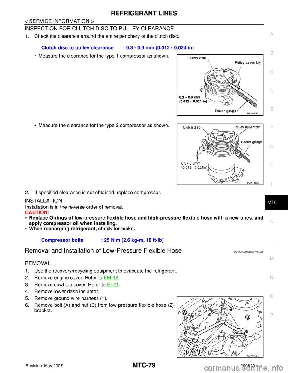
INSPECTION FOR CLUTCH DISC TO PULLEY CLEARANCE
1. Check the clearance around the entire periphery of the clutch disc.
• Measure the clearance for the type 1 compressor as shown.
• Measure the clearance for the type 2 compressor as shown.
2. If specified clearance is not obtained, replace compressor.
INSTALLATION
Installation is in the reverse order of removal.
CAUTION:
• Replace O-rings of low-pressure flexible hose and high-pressure flexible hose with a new ones, and
apply compressor oil when installing.
• When recharging refrigerant, check for leaks.
Removal and Installation of Low-Pressure Flexible HoseINFOID:0000000001704325
REMOVAL
1. Use the recovery/recycling equipment to evacuate the refrigerant.
2. Remove engine cover. Refer to EM-18
.
3. Remove cowl top cover. Refer to EI-21
.
4. Remove lower dash insulator.
5. Remove ground wire harness (1).
6. Remove bolt (A) and nut (B) from low-pressure flexible hose (2)
bracket.Clutch disc to pulley clearance : 0.3 - 0.6 mm (0.012 - 0.024 in)
RHA087E
RJIA1886E
Compressor bolts : 25 N·m (2.6 kg-m, 18 ft-lb)
SJIA0675E
Page 2608 of 2771

SC-26
< SERVICE INFORMATION >
SERVICE DATA AND SPECIFICATIONS (SDS)
SERVICE DATA AND SPECIFICATIONS (SDS)
BatteryINFOID:0000000001704356
StarterINFOID:0000000001704357
GeneratorINFOID:0000000001704358
M/T, A/T CVT
Type TR4 Gr.51 R
20 hours rate capacity 12 V - 47 AH 12 V - 47 AH
Cold Cranking Amps. (CCA) 470 470
Typ eS114 - 901
HITACHI make
Reduction gear type
System voltage12 V
No-loadTerminal voltage 11 V
Current Less than 110 A
Revolution More than 3,000 rpm
Minimum diameter of commutator 28.0 mm (1.102 in)
Minimum length of brush 10.5 mm (0.413 in)
Brush spring tension 16.2 N (1.65 kg, 3.64 lb)
Clearance between bearing metal and armature shaft Less than 0.2 mm (0.008 in)
Movement “L” in height of pinion assembly 0.3 - 2.5 mm (0.012 - 0.098 in)
Ty p eLR1140 - 803
MITSUBISHI make
Nominal rating12 V - 140 A
Ground polarityNegative
Minimum revolution under no-load (when 13.5 V is applied) Less than 1,200 rpm
Hot output current (when 13.5 V is applied)More than 27 A/1,300 rpm
More than 95 A/2,500 rpm
More than 116 A/5,000 rpm
Regulated output voltage14.1 - 14.7 V
Minimum length of brush More than 6.00 mm (0.236 in)
Brush spring pressure 1.1 - 3.7 N (112 - 378 g, 4.00 - 13.3 oz)
Slip ring minimum outer diameter More than 14.7 mm (0.579 in)
Rotor (field coil) resistance 1.61 - 1.91 Ω
Page 2686 of 2771
![NISSAN TIIDA 2008 Service Repair Manual PRECAUTIONS
STC-3
< SERVICE INFORMATION >[EPS]
C
D
E
F
H
I
J
K
L
MA
B
STC
N
O
P
• Check any possible causes by interviewing the symptom and it’s condition from the customer if any
malfunction, suc NISSAN TIIDA 2008 Service Repair Manual PRECAUTIONS
STC-3
< SERVICE INFORMATION >[EPS]
C
D
E
F
H
I
J
K
L
MA
B
STC
N
O
P
• Check any possible causes by interviewing the symptom and it’s condition from the customer if any
malfunction, suc](/img/5/57399/w960_57399-2685.png)
PRECAUTIONS
STC-3
< SERVICE INFORMATION >[EPS]
C
D
E
F
H
I
J
K
L
MA
B
STC
N
O
P
• Check any possible causes by interviewing the symptom and it’s condition from the customer if any
malfunction, such as EPS warning lamp turns ON, occurs.
• Check if air pressure and size of tires are proper, the specified part is used for the steering wheel,
and control unit is genuine part.
• Check if the connection of steering column assembly and steering gear assembly is proper (there is
not looseness of mounting bolts, damage of rods, boots or sealants, and leakage of grease, etc).
• Check if the wheel alignment is adjusted properly.
• Check if there is any damage or modification to suspension or body resulting in increased weight or
altered ground clearance.
• Check if installation conditions of each link and suspension are proper.
• Check if the battery voltage is proper
• Check connection conditions of each connector are proper.
• Before connecting or disconnecting the EPS control unit har-
ness connector, turn ignition switch “OFF” and disconnect
battery ground cable. Because battery voltage is applied to
EPS control unit even if ignition switch is turned “OFF”.
• When connecting or disconnecting pin connectors into or
from EPS control unit, take care not to damage pin terminals
(bend or break).
When connecting pin connectors, make sure that there are no
bends or breaks on EPS control unit pin terminal.
• Before replacing EPS control unit, perform EPS control unit
input/output signal inspection and make sure whether EPS
control unit functions properly or not. Refer to STC-9, "
EPS
Control Unit Input/Output Signal Reference Value".
SEF289H
SEF291H
SDIA1848E