nissan connect NISSAN TIIDA 2008 Service Repair Manual
[x] Cancel search | Manufacturer: NISSAN, Model Year: 2008, Model line: TIIDA, Model: NISSAN TIIDA 2008Pages: 2771, PDF Size: 60.61 MB
Page 9 of 2771

ACC-2
< SERVICE INFORMATION >
PRECAUTIONS
SERVICE INFORMATION
PRECAUTIONS
Precaution for Supplemental Restraint System (SRS) "AIR BAG" and "SEAT BELT
PRE-TENSIONER"
INFOID:0000000001703109
The Supplemental Restraint System such as “AIR BAG” and “SEAT BELT PRE-TENSIONER”, used along
with a front seat belt, helps to reduce the risk or severity of injury to the driver and front passenger for certain
types of collision. This system includes seat belt switch inputs and dual stage front air bag modules. The SRS
system uses the seat belt switches to determine the front air bag deployment, and may only deploy one front
air bag, depending on the severity of a collision and whether the front occupants are belted or unbelted.
Information necessary to service the system safely is included in the SR and SB section of this Service Man-
ual.
WARNING:
• To avoid rendering the SRS inoperative, which could increase the risk of personal injury or death in
the event of a collision which would result in air bag inflation, all maintenance must be performed by
an authorized NISSAN/INFINITI dealer.
• Improper maintenance, including incorrect removal and installation of the SRS, can lead to personal
injury caused by unintentional activation of the system. For removal of Spiral Cable and Air Bag
Module, see the SR section.
• Do not use electrical test equipment on any circuit related to the SRS unless instructed to in this
Service Manual. SRS wiring harnesses can be identified by yellow and/or orange harnesses or har-
ness connectors.
Page 19 of 2771

PRECAUTIONS
AT-7
< SERVICE INFORMATION >
D
E
F
G
H
I
J
K
L
MA
B
AT
N
O
P
PRECAUTIONS
Precaution for Supplemental Restraint System (SRS) "AIR BAG" and "SEAT BELT
PRE-TENSIONER"
INFOID:0000000001703151
The Supplemental Restraint System such as “AIR BAG” and “SEAT BELT PRE-TENSIONER”, used along
with a front seat belt, helps to reduce the risk or severity of injury to the driver and front passenger for certain
types of collision. This system includes seat belt switch inputs and dual stage front air bag modules. The SRS
system uses the seat belt switches to determine the front air bag deployment, and may only deploy one front
air bag, depending on the severity of a collision and whether the front occupants are belted or unbelted.
Information necessary to service the system safely is included in the SRS and SB section of this Service Man-
ual.
WARNING:
• To avoid rendering the SRS inoperative, which could increase the risk of personal injury or death in
the event of a collision which would result in air bag inflation, all maintenance must be performed by
an authorized NISSAN/INFINITI dealer.
• Improper maintenance, including incorrect removal and installation of the SRS, can lead to personal
injury caused by unintentional activation of the system. For removal of Spiral Cable and Air Bag
Module, see the SRS section.
• Do not use electrical test equipment on any circuit related to the SRS unless instructed to in this
Service Manual. SRS wiring harnesses can be identified by yellow and/or orange harnesses or har-
ness connectors.
Precaution Necessary for Steering Wheel Rotation After Battery Disconnect
INFOID:0000000001703152
NOTE:
• This Procedure is applied only to models with Intelligent Key system and NVIS/IVIS (NISSAN/INFINITI
VEHICLE IMMOBILIZER SYSTEM - NATS).
• Remove and install all control units after disconnecting both battery cables with the ignition knob in the
″LOCK″ position.
• Always use CONSULT-III to perform self-diagnosis as a part of each function inspection after finishing work.
If DTC is detected, perform trouble diagnosis according to self-diagnostic results.
For models equipped with the Intelligent Key system and NVIS/IVIS, an electrically controlled steering lock
mechanism is adopted on the key cylinder.
For this reason, if the battery is disconnected or if the battery is discharged, the steering wheel will lock and
steering wheel rotation will become impossible.
If steering wheel rotation is required when battery power is interrupted, follow the procedure below before
starting the repair operation.
OPERATION PROCEDURE
1. Connect both battery cables.
NOTE:
Supply power using jumper cables if battery is discharged.
2. Use the Intelligent Key or mechanical key to turn the ignition switch to the ″ACC″ position. At this time, the
steering lock will be released.
3. Disconnect both battery cables. The steering lock will remain released and the steering wheel can be
rotated.
4. Perform the necessary repair operation.
5. When the repair work is completed, return the ignition switch to the ″LOCK″ position before connecting
the battery cables. (At this time, the steering lock mechanism will engage.)
6. Perform a self-diagnosis check of all control units using CONSULT-III.
Precaution for On Board Diagnosis (OBD) System of A/T and EngineINFOID:0000000001703153
The ECM has an on board diagnostic system. It will light up the malfunction indicator lamp (MIL) to warn the
driver of a malfunction causing emission deterioration.
CAUTION:
Page 28 of 2771
AT-16
< SERVICE INFORMATION >
A/T FLUID
5. Run engine at idle speed for 5 minutes.
6. Check A/T fluid level and condition. Refer to MA-22, "
Checking A/T Fluid".
A/T Fluid Cooler CleaningINFOID:0000000001703160
Whenever the A/T is repaired, overhauled, or replaced, the A/T fluid cooler mounted in the radiator must be
inspected and cleaned.
Metal debris and friction material, if present, can become trapped in the A/T fluid cooler. This debris can con-
taminate the newly serviced A/T or, in severe cases, can block or restrict the flow of A/T fluid. In either case,
malfunction of the newly serviced A/T may result.
Debris, if present, may build up as A/T fluid enters the cooler inlet. It will be necessary to back flush the cooler
through the cooler outlet in order to flush out any built up debris.
A/T FLUID COOLER CLEANING PROCEDURE
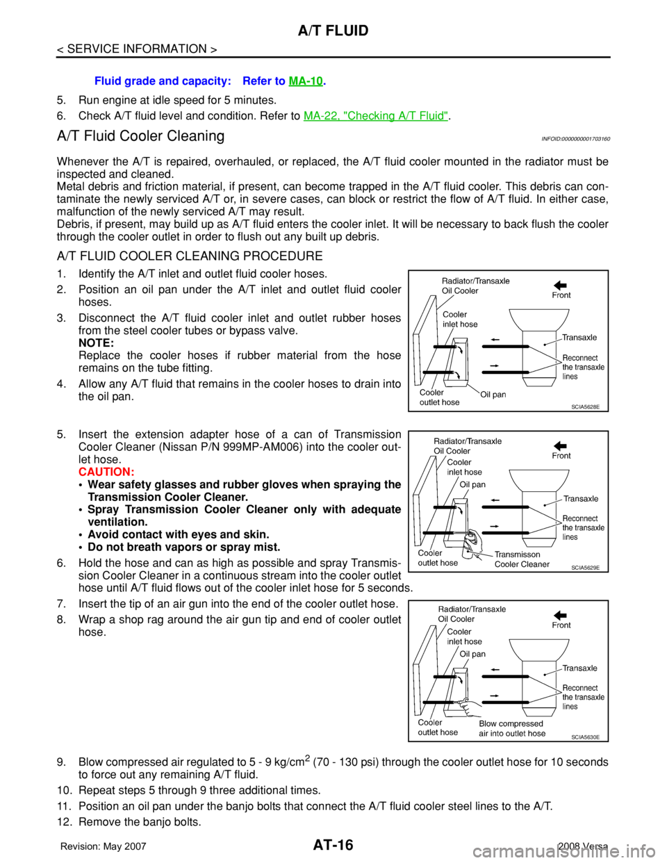
1. Identify the A/T inlet and outlet fluid cooler hoses.
2. Position an oil pan under the A/T inlet and outlet fluid cooler
hoses.
3. Disconnect the A/T fluid cooler inlet and outlet rubber hoses
from the steel cooler tubes or bypass valve.
NOTE:
Replace the cooler hoses if rubber material from the hose
remains on the tube fitting.
4. Allow any A/T fluid that remains in the cooler hoses to drain into
the oil pan.
5. Insert the extension adapter hose of a can of Transmission
Cooler Cleaner (Nissan P/N 999MP-AM006) into the cooler out-
let hose.
CAUTION:
• Wear safety glasses and rubber gloves when spraying the
Transmission Cooler Cleaner.
• Spray Transmission Cooler Cleaner only with adequate
ventilation.
• Avoid contact with eyes and skin.
• Do not breath vapors or spray mist.
6. Hold the hose and can as high as possible and spray Transmis-
sion Cooler Cleaner in a continuous stream into the cooler outlet
hose until A/T fluid flows out of the cooler inlet hose for 5 seconds.
7. Insert the tip of an air gun into the end of the cooler outlet hose.
8. Wrap a shop rag around the air gun tip and end of cooler outlet
hose.
9. Blow compressed air regulated to 5 - 9 kg/cm
2 (70 - 130 psi) through the cooler outlet hose for 10 seconds
to force out any remaining A/T fluid.
10. Repeat steps 5 through 9 three additional times.
11. Position an oil pan under the banjo bolts that connect the A/T fluid cooler steel lines to the A/T.
12. Remove the banjo bolts.Fluid grade and capacity: Refer to MA-10
.
SCIA5628E
SCIA5629E
SCIA5630E
Page 361 of 2771

AV-2
< SERVICE INFORMATION >
PRECAUTIONS
SERVICE INFORMATION
PRECAUTIONS
Precaution for Supplemental Restraint System (SRS) "AIR BAG" and "SEAT BELT
PRE-TENSIONER"
INFOID:0000000001704647
The Supplemental Restraint System such as “AIR BAG” and “SEAT BELT PRE-TENSIONER”, used along
with a front seat belt, helps to reduce the risk or severity of injury to the driver and front passenger for certain
types of collision. This system includes seat belt switch inputs and dual stage front air bag modules. The SRS
system uses the seat belt switches to determine the front air bag deployment, and may only deploy one front
air bag, depending on the severity of a collision and whether the front occupants are belted or unbelted.
Information necessary to service the system safely is included in the SR and SB section of this Service Man-
ual.
WARNING:
• To avoid rendering the SRS inoperative, which could increase the risk of personal injury or death in
the event of a collision which would result in air bag inflation, all maintenance must be performed by
an authorized NISSAN/INFINITI dealer.
• Improper maintenance, including incorrect removal and installation of the SRS, can lead to personal
injury caused by unintentional activation of the system. For removal of Spiral Cable and Air Bag
Module, see the SR section.
• Do not use electrical test equipment on any circuit related to the SRS unless instructed to in this
Service Manual. SRS wiring harnesses can be identified by yellow and/or orange harnesses or har-
ness connectors.
Page 402 of 2771
TELEPHONE
AV-43
< SERVICE INFORMATION >
C
D
E
F
G
H
I
J
L
MA
B
AV
N
O
P
TELEPHONE
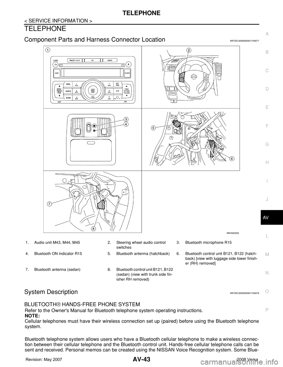
Component Parts and Harness Connector LocationINFOID:0000000001704677
System DescriptionINFOID:0000000001704678
BLUETOOTH® HANDS-FREE PHONE SYSTEM
Refer to the Owner's Manual for Bluetooth telephone system operating instructions.
NOTE:
Cellular telephones must have their wireless connection set up (paired) before using the Bluetooth telephone
system.
Bluetooth telephone system allows users who have a Bluetooth cellular telephone to make a wireless connec-
tion between their cellular telephone and the Bluetooth control unit. Hands-free cellular telephone calls can be
sent and received. Personal memos can be created using the NISSAN Voice Recognition system. Some Blue-
WKIA6000E
1. Audio unit M43, M44, M45 2. Steering wheel audio control
switches3. Bluetooth microphone R15
4. Bluetooth ON indicator R15 5. Bluetooth antenna (hatchback) 6. Bluetooth control unit B121, B122 (hatch-
back) [view with luggage side lower finish-
er (RH) removed]
7. Bluetooth antenna (sedan) 8. Bluetooth control unit B121, B122
(sedan) (view with trunk side fin-
isher RH removed)
Page 403 of 2771
AV-44
< SERVICE INFORMATION >
TELEPHONE
tooth cellular telephones may not be recognized by the Bluetooth control unit. When a cellular telephone or
the Bluetooth control unit is replaced, the telephone must be paired with the Bluetooth control unit. Different
cellular telephones may have different pairing procedures. Refer to the cellular telephone operating manual.
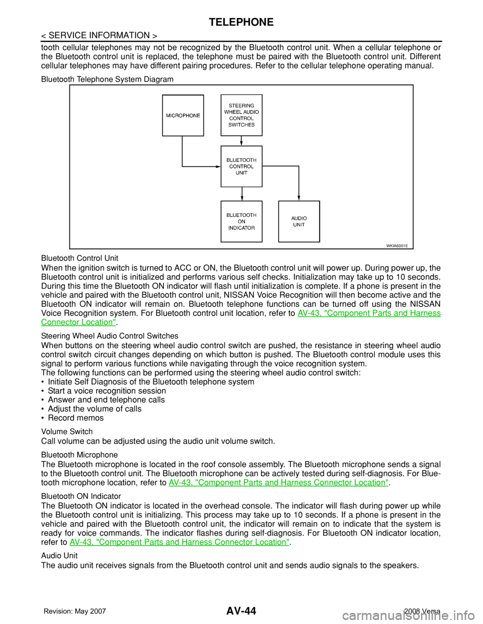
Bluetooth Telephone System Diagram
Bluetooth Control Unit
When the ignition switch is turned to ACC or ON, the Bluetooth control unit will power up. During power up, the
Bluetooth control unit is initialized and performs various self checks. Initialization may take up to 10 seconds.
During this time the Bluetooth ON indicator will flash until initialization is complete. If a phone is present in the
vehicle and paired with the Bluetooth control unit, NISSAN Voice Recognition will then become active and the
Bluetooth ON indicator will remain on. Bluetooth telephone functions can be turned off using the NISSAN
Voice Recognition system. For Bluetooth control unit location, refer to AV-43, "
Component Parts and Harness
Connector Location".
Steering Wheel Audio Control Switches
When buttons on the steering wheel audio control switch are pushed, the resistance in steering wheel audio
control switch circuit changes depending on which button is pushed. The Bluetooth control module uses this
signal to perform various functions while navigating through the voice recognition system.
The following functions can be performed using the steering wheel audio control switch:
• Initiate Self Diagnosis of the Bluetooth telephone system
• Start a voice recognition session
• Answer and end telephone calls
• Adjust the volume of calls
• Record memos
Volume Switch
Call volume can be adjusted using the audio unit volume switch.
Bluetooth Microphone
The Bluetooth microphone is located in the roof console assembly. The Bluetooth microphone sends a signal
to the Bluetooth control unit. The Bluetooth microphone can be actively tested during self-diagnosis. For Blue-
tooth microphone location, refer to AV-43, "
Component Parts and Harness Connector Location".
Bluetooth ON Indicator
The Bluetooth ON indicator is located in the overhead console. The indicator will flash during power up while
the Bluetooth control unit is initializing. This process may take up to 10 seconds. If a phone is present in the
vehicle and paired with the Bluetooth control unit, the indicator will remain on to indicate that the system is
ready for voice commands. The indicator flashes during self-diagnosis. For Bluetooth ON indicator location,
refer to AV-43, "
Component Parts and Harness Connector Location".
Audio Unit
The audio unit receives signals from the Bluetooth control unit and sends audio signals to the speakers.
WKIA6001E
Page 418 of 2771

BCS-2
< SERVICE INFORMATION >
PRECAUTIONS
SERVICE INFORMATION
PRECAUTIONS
Precaution for Supplemental Restraint System (SRS) "AIR BAG" and "SEAT BELT
PRE-TENSIONER"
INFOID:0000000001704583
The Supplemental Restraint System such as “AIR BAG” and “SEAT BELT PRE-TENSIONER”, used along
with a front seat belt, helps to reduce the risk or severity of injury to the driver and front passenger for certain
types of collision. This system includes seat belt switch inputs and dual stage front air bag modules. The SRS
system uses the seat belt switches to determine the front air bag deployment, and may only deploy one front
air bag, depending on the severity of a collision and whether the front occupants are belted or unbelted.
Information necessary to service the system safely is included in the SR and SB section of this Service Man-
ual.
WARNING:
• To avoid rendering the SRS inoperative, which could increase the risk of personal injury or death in
the event of a collision which would result in air bag inflation, all maintenance must be performed by
an authorized NISSAN/INFINITI dealer.
• Improper maintenance, including incorrect removal and installation of the SRS, can lead to personal
injury caused by unintentional activation of the system. For removal of Spiral Cable and Air Bag
Module, see the SR section.
• Do not use electrical test equipment on any circuit related to the SRS unless instructed to in this
Service Manual. SRS wiring harnesses can be identified by yellow and/or orange harnesses or har-
ness connectors.
Page 437 of 2771

BL-3
C
D
E
F
G
H
J
K
L
MA
B
BL
N
O
P
FUEL FILLER LID OPENER ............................186
Removal and Installation of Fuel Filler Lid Opener ..186
VEHICLE SECURITY (THEFT WARNING)
SYSTEM ...........................................................
187
Component Parts and Harness Connector Loca-
tion ........................................................................
187
System Description ...............................................188
CAN Communication System Description .............190
Schematic .............................................................191
Wiring Diagram - VEHSEC - .................................192
Terminal and Reference Value for BCM ...............195
Terminal and Reference Value for Intelligent Key
Unit ........................................................................
195
CONSULT-III Function (BCM) ...............................196
Trouble Diagnosis .................................................197
Preliminary Check .................................................197
Symptom Chart .....................................................199
Diagnosis Procedure 1 ..........................................200
Diagnosis Procedure 2 ..........................................203
Diagnosis Procedure 3 ..........................................204
Diagnosis Procedure 4 ..........................................204
Diagnosis Procedure 5 ..........................................204
Diagnosis Procedure 6 ..........................................204
Diagnosis Procedure 7 ..........................................204
Diagnosis Procedure 8 ..........................................206
Diagnosis Procedure 9 ..........................................207
NATS (Nissan Anti-Theft System) .................210
Component Parts and Harness Connector Loca-
tion .........................................................................
210
System Description ................................................210
System Composition ..............................................211
ECM Re-communicating Function .........................211
Wiring Diagram - NATS - .......................................213
Terminal and Reference Value for BCM ................213
CONSULT-III Function ..........................................213
Trouble Diagnosis Procedure ................................215
Trouble Diagnosis ..................................................217
Diagnosis Procedure 1 ..........................................218
Diagnosis Procedure 2 ..........................................220
Diagnosis Procedure 3 ..........................................221
Diagnosis Procedure 4 ..........................................222
Diagnosis Procedure 5 ..........................................223
How to Replace NATS Antenna Amp ....................224
BODY REPAIR ................................................225
Body Exterior Paint Color ......................................225
Body Component Parts .........................................227
Corrosion Protection ..............................................232
Body Sealing .........................................................236
Body Construction .................................................242
Body Alignment .....................................................244
Handling Precaution for Plastics ............................261
Precaution in Repairing High Strength Steel .........265
Foam Repair ..........................................................268
Replacement Operation .........................................271
Page 438 of 2771

BL-4
< SERVICE INFORMATION >
PRECAUTIONS
SERVICE INFORMATION
PRECAUTIONS
Precaution for Supplemental Restraint System (SRS) "AIR BAG" and "SEAT BELT
PRE-TENSIONER"
INFOID:0000000001703938
The Supplemental Restraint System such as “AIR BAG” and “SEAT BELT PRE-TENSIONER”, used along
with a front seat belt, helps to reduce the risk or severity of injury to the driver and front passenger for certain
types of collision. This system includes seat belt switch inputs and dual stage front air bag modules. The SRS
system uses the seat belt switches to determine the front air bag deployment, and may only deploy one front
air bag, depending on the severity of a collision and whether the front occupants are belted or unbelted.
Information necessary to service the system safely is included in the SRS and SB section of this Service Man-
ual.
WARNING:
• To avoid rendering the SRS inoperative, which could increase the risk of personal injury or death in
the event of a collision which would result in air bag inflation, all maintenance must be performed by
an authorized NISSAN/INFINITI dealer.
• Improper maintenance, including incorrect removal and installation of the SRS, can lead to personal
injury caused by unintentional activation of the system. For removal of Spiral Cable and Air Bag
Module, see the SRS section.
• Do not use electrical test equipment on any circuit related to the SRS unless instructed to in this
Service Manual. SRS wiring harnesses can be identified by yellow and/or orange harnesses or har-
ness connectors.
Precaution Necessary for Steering Wheel Rotation After Battery Disconnect
INFOID:0000000001703939
NOTE:
• This procedure is applied only to models with Intelligent Key system and NVIS/IVIS (NISSAN/INFINITI
VEHICLE IMMOBILIZER SYSTEM - NATS).
• Remove and install all control units after disconnecting both battery cables with the ignition in the ″LOCK″
position.
• Always use CONSULT-III to perform self-diagnosis as a part of each function inspection after finishing work.
If DTC is detected, perform trouble diagnosis according to self-diagnostic results.
For models equipped with the Intelligent Key system and NVIS/IVIS, an electrically controlled steering lock
mechanism is adopted on the key cylinder.
For this reason, if the battery is disconnected or if the battery is discharged, the steering wheel will lock and
steering wheel rotation will become impossible.
If steering wheel rotation is required when battery power is interrupted, follow the procedure below before
starting the repair operation.
OPERATION PROCEDURE
1. Connect both battery cables.
NOTE:
Supply power using jumper cables if battery is discharged.
2. Use the Intelligent Key or mechanical key to turn the ignition switch to the ″ACC″ position. At this time, the
steering lock will be released.
3. Disconnect both battery cables. The steering lock will remain released and the steering wheel can be
rotated.
4. Perform the necessary repair operation.
5. When the repair work is completed, return the ignition switch to the ″LOCK″ position before connecting
the battery cables. (At this time, the steering lock mechanism will engage.)
6. Perform a self-diagnosis check of all control units using CONSULT-III.
Page 442 of 2771

BL-8
< SERVICE INFORMATION >
SQUEAK AND RATTLE TROUBLE DIAGNOSES
If the noise can be duplicated easily during the test drive, to help identify the source of the noise, try to dupli-
cate the noise with the vehicle stopped by doing one or all of the following:
1) Close a door.
2) Tap or push/pull around the area where the noise appears to be coming from.
3) Rev the engine.
4) Use a floor jack to recreate vehicle “twist”.
5) At idle, apply engine load (electrical load, half-clutch on M/T model, drive position on A/T model).
6) Raise the vehicle on a hoist and hit a tire with a rubber hammer.
• Drive the vehicle and attempt to duplicate the conditions the customer states exist when the noise occurs.
• If it is difficult to duplicate the noise, drive the vehicle slowly on an undulating or rough road to stress the
vehicle body.
CHECK RELATED SERVICE BULLETINS
After verifying the customer concern or symptom, check ASIST for Technical Service Bulletins (TSBs) related
to that concern or symptom.
If a TSB relates to the symptom, follow the procedure to repair the noise.
LOCATE THE NOISE AND IDENTIFY THE ROOT CAUSE
1. Narrow down the noise to a general area.To help pinpoint the source of the noise, use a listening tool
(Chassis Ear: J-39570, Engine Ear: J-39565 and mechanic's stethoscope).
2. Narrow down the noise to a more specific area and identify the cause of the noise by:
• removing the components in the area that you suspect the noise is coming from.
Do not use too much force when removing clips and fasteners, otherwise clips and fasteners can be broken
or lost during the repair, resulting in the creation of new noise.
• tapping or pushing/pulling the component that you suspect is causing the noise.
Do not tap or push/pull the component with excessive force, otherwise the noise will be eliminated only tem-
porarily.
• feeling for a vibration with your hand by touching the component(s) that you suspect is (are) causing the
noise.
• placing a piece of paper between components that you suspect are causing the noise.
• looking for loose components and contact marks.
Refer to BL-9, "
Generic Squeak and Rattle Troubleshooting".
REPAIR THE CAUSE
• If the cause is a loose component, tighten the component securely.
• If the cause is insufficient clearance between components:
- separate components by repositioning or loosening and retightening the component, if possible.
- insulate components with a suitable insulator such as urethane pads, foam blocks, felt cloth tape or urethane
tape. A NISSAN Squeak and Rattle Kit (J-43980) is available through your authorized NISSAN Parts Depart-
ment.
CAUTION:
Do not use excessive force as many components are constructed of plastic and may be damaged.
Always check with the Parts Department for the latest parts information.
The following materials are contained in the NISSAN Squeak and Rattle Kit (J-43980). Each item can be
ordered separately as needed.
URETHANE PADS [1.5 mm (0.059 in) thick]
Insulates connectors, harness, etc.
76268-9E005: 100×135 mm (3.94×5.31 in)/76884-71L01: 60×85 mm (2.36×3.35 in)/76884-71L02: 15×25
mm (0.59×0.98 in)
INSULATOR (Foam blocks)
Insulates components from contact. Can be used to fill space behind a panel.
73982-9E000: 45 mm (1.77 in) thick, 50×50 mm (1.97×1.97 in)/73982-50Y00: 10 mm (0.39 in) thick,
50×50 mm (1.97×1.97 in)
INSULATOR (Light foam block)
80845-71L00: 30 mm (1.18 in) thick, 30×50 mm (1.18×1.97 in)
FELT CLOTH TAPE
Used to insulate where movement does not occur. Ideal for instrument panel applications.
68370-4B000: 15×25 mm (0.59×0.98 in) pad/68239-13E00: 5 mm (0.20 in) wide tape roll. The following
materials not found in the kit can also be used to repair squeaks and rattles.
UHMW (TEFLON) TAPE
Insulates where slight movement is present. Ideal for instrument panel applications.