wiring diagram NISSAN TIIDA 2009 Service Owners Manual
[x] Cancel search | Manufacturer: NISSAN, Model Year: 2009, Model line: TIIDA, Model: NISSAN TIIDA 2009Pages: 4331, PDF Size: 58.04 MB
Page 1361 of 4331
EC
A
N
O P
Diagnosis Procedure ...........................................
..
349
P0507 ISC SYSTEM ....................................... ..351
Description .......................................................... ..351
DTC Logic ........................................................... ..351
Diagnosis Procedure ........................................... ..351
P0603 ECM POWER SUPPLY ....................... ..353
Description .......................................................... ..353
DTC Logic ........................................................... ..353
Diagnosis Procedure ........................................... ..353
P0605 ECM ..................................................... ..355
Description .......................................................... ..355
DTC Logic ........................................................... ..355
Diagnosis Procedure ........................................... ..356
P0607 ECM ..................................................... ..357
Description .......................................................... ..357
DTC Logic ........................................................... ..357
Diagnosis Procedure ........................................... ..357
P0643 SENSOR POWER SUPPLY ............... ..358
DTC Logic ........................................................... ..358
Wiring Diagram ................................................... ..359
Diagnosis Procedure ........................................... ..359
P0850 PNP SWITCH ...................................... ..362
Description .......................................................... ..362
DTC Logic ........................................................... ..362
Component Function Check ................................ ..363
Wiring Diagram ................................................... ..364
Diagnosis Procedure ........................................... ..364
P1148 CLOSED LOOP CONTROL ................ ..367
DTC Logic ........................................................... ..367
P1217 ENGINE OVER TEMPERATURE ....... ..368
DTC Logic ........................................................... ..368
Component Function Check ................................ ..368
Diagnosis Procedure ........................................... ..369
P1225 TP SENSOR ........................................ ..372
Description .......................................................... ..372
DTC Logic ........................................................... ..372
Diagnosis Procedure ........................................... ..372
Special Repair Requirem ent .................................373
P1226 TP SENSOR ........................................ ..374
Description .......................................................... ..374
DTC Logic ........................................................... ..374
Diagnosis Procedure ........................................... ..374
Special Repair Requirem ent .................................375
P1421 COLD START CONTROL ................... ..376
Description .......................................................... ..376
DTC Logic ........................................................... ..376
Diagnosis Procedure ........................................... ..376
P1715 INPUT SPEED SENSOR (PRIMARY
SPEED SENSOR) .......................................... ..
378
Description .......................................................... ..378 DTC Logic ............................................................
..378
Diagnosis Procedure ........................................... ..378
P1805 BRAKE SWITCH ................................. 380
Description ........................................................... ..380
DTC Logic ............................................................ ..380
Wiring Diagram .................................................... ..381
Diagnosis Procedure ........................................... ..381
Component Inspection (Stop Lamp Switch) ........ ..383
P2100, P2103 THROTTLE CONTROL MO-
TOR RELAY .................................................... 384
Description ........................................................... ..384
DTC Logic ............................................................ ..384
Wiring Diagram .................................................... ..385
Diagnosis Procedure ........................................... ..385
P2101 ELECTRIC THROTTLE CONTROL
FUNCTION ....... ............................................... 388
Description ........................................................... ..388
DTC Logic ............................................................ ..388
Wiring Diagram .................................................... ..389
Diagnosis Procedure ........................................... ..389
Component Inspection ......................................... ..392
Special Repair Requiremen t ..................................392
P2118 THROTTLE CONTROL MOTOR ......... 393
Description ........................................................... ..393
DTC Logic ............................................................ ..393
Wiring Diagram .................................................... ..394
Diagnosis Procedure ........................................... ..394
Component Inspection ......................................... ..395
Special Repair Requiremen t ..................................396
P2119 ELECTRIC THROTTLE CONTROL
ACTUATOR ..................................................... 397
Description ........................................................... ..397
DTC Logic ............................................................ ..397
Diagnosis Procedure ........................................... ..397
Special Repair Requiremen t ..................................398
P2122, P2123 APP SENSOR ......................... 399
Description ........................................................... ..399
DTC Logic ............................................................ ..399
Wiring Diagram .................................................... ..400
Diagnosis Procedure ........................................... ..400
Component Inspection ......................................... ..402
Special Repair Requiremen t ..................................402
P2127, P2128 APP SENSOR ......................... 403
Description ........................................................... ..403
DTC Logic ............................................................ ..403
Wiring Diagram .................................................... ..404
Diagnosis Procedure ........................................... ..404
Component Inspection ......................................... ..406
Special Repair Requiremen t ..................................407
P2135 TP SENSOR ......................................... 408
Description ........................................................... ..408
DTC Logic ............................................................ ..408
Page 1365 of 4331
EC
A
N
O P
Component Description .......................................
..
679
CONSULT-III Refe rence Value in Data Monitor
Mode ................................................................... ..
679
On Board Diagnosis Logic .................................. ..679
DTC Confirmation Procedure .............................. ..679
Wiring Diagram ................................................... ..680
Diagnosis Procedure ........................................... ..681
Component Inspection ........................................ ..683
Removal and Installation .......................................683
DTC P0125 ECT SENSOR ............................. ..684
Description .......................................................... ..684
On Board Diagnosis Logic .................................. ..684
DTC Confirmation Procedure .............................. ..684
Diagnosis Procedure ........................................... ..685
Component Inspection ........................................ ..686
Removal and Installation .......................................686
DTC P0127 IAT SENSOR .............................. ..687
Component Description ....................................... ..687
On Board Diagnosis Logic .................................. ..687
DTC Confirmation Procedure .............................. ..687
Diagnosis Procedure ........................................... ..688
Component Inspection ........................................ ..688
Removal and Installation .......................................689
DTC P0128 THERMOSTAT FUNCTION ........ ..690
On Board Diagnosis Logic .................................. ..690
DTC Confirmation Procedure .............................. ..690
Diagnosis Procedure ........................................... ..690
Component Inspection ........................................ ..691
Removal and Installation .......................................691
DTC P0130 A/F SENSOR 1 ........................... ..692
Component Description ....................................... ..692
CONSULT-III Refe rence Value in Data Monitor
Mode ................................................................... ..
692
On Board Diagnosis Logic .................................. ..692
DTC Confirmation Procedure .............................. ..692
Overall Function Check ....................................... ..693
Wiring Diagram ................................................... ..694
Diagnosis Procedure ........................................... ..695
Removal and Installation .......................................697
DTC P0131 A/F SENSOR 1 ........................... ..698
Component Description ....................................... ..698
CONSULT-III Refe rence Value in Data Monitor
Mode ................................................................... ..
698
On Board Diagnosis Logic .................................. ..698
DTC Confirmation Procedure .............................. ..698
Wiring Diagram ................................................... ..700
Diagnosis Procedure ........................................... ..701
Removal and Installation .......................................703
DTC P0132 A/F SENSOR 1 ........................... ..704
Component Description ....................................... ..704
CONSULT-III Refe rence Value in Data Monitor
Mode ................................................................... ..
704
On Board Diagnosis Logic .................................. ..704
DTC Confirmation Procedure .............................. ..704 Wiring Diagram ....................................................
..706
Diagnosis Procedure ........................................... ..707
Removal and Installation ..................................... ..709
DTC P0133 A/F SENSOR 1 ............................ 710
Component Description ....................................... ..710
CONSULT-III Reference Va lue in Data Monitor
Mode .................................................................... ..
710
On Board Diagnosis Logic ................................... ..710
DTC Confirmation Procedure .............................. ..710
Wiring Diagram .................................................... ..712
Diagnosis Procedure ........................................... ..713
Removal and Installation ..................................... ..716
DTC P0137 HO2S2 ......................................... 717
Component Description ....................................... ..717
CONSULT-III Reference Va lue in Data Monitor
Mode .................................................................... ..
717
On Board Diagnosis Logic ................................... ..717
DTC Confirmation Procedure .............................. ..717
Overall Function Check ....................................... ..718
Wiring Diagram .................................................... ..719
Diagnosis Procedure ........................................... ..720
Component Inspection ......................................... ..722
Removal and Installation ..................................... ..723
DTC P0138 HO2S2 ......................................... 724
Component Description ....................................... ..724
CONSULT-III Reference Va lue in Data Monitor
Mode .................................................................... ..
724
On Board Diagnosis Logic ................................... ..724
DTC Confirmation Procedure .............................. ..725
Overall Function Check ....................................... ..725
Wiring Diagram .................................................... ..727
Diagnosis Procedure ........................................... ..728
Component Inspection ......................................... ..731
Removal and Installation ..................................... ..732
DTC P0139 HO2S2 ......................................... 733
Component Description ....................................... ..733
CONSULT-III Reference Va lue in Data Monitor
Mode .................................................................... ..
733
On Board Diagnosis Logic ................................... ..733
DTC Confirmation Procedure .............................. ..733
Overall Function Check ....................................... ..734
Wiring Diagram .................................................... ..735
Diagnosis Procedure ........................................... ..736
Component Inspection ......................................... ..738
Removal and Installation ..................................... ..739
DTC P0171 FUEL INJECTION SYSTEM
FUNCTION ....... ...............................................
740
On Board Diagnosis Logic ................................... ..740
DTC Confirmation Procedure .............................. ..740
Wiring Diagram .................................................... ..742
Diagnosis Procedure ........................................... ..743
DTC P0172 FUEL INJECTION SYSTEM
FUNCTION ....... ............................................... 746
On Board Diagnosis Logic ...................................
Page 1367 of 4331
EC
A
N
O P
Wiring Diagram ...................................................
..
818
Diagnosis Procedure ........................................... ..819
Component Inspection ........................................ ..821
DTC P0448 EVAP CANISTER VENT CON-
TROL VALVE ................................................. ..823
Component Description ....................................... ..823
CONSULT-III Refe rence Value in Data Monitor
Mode ................................................................... ..
823
On Board Diagnosis Logic .................................. ..823
DTC Confirmation Procedure .............................. ..823
Wiring Diagram ................................................... ..825
Diagnosis Procedure ........................................... ..826
Component Inspection ........................................ ..827
DTC P0451 EVAP CONTROL SYSTEM
PRESSURE SENSO R .................................... ..829
Component Description ....................................... ..829
CONSULT-III Refe rence Value in Data Monitor
Mode ................................................................... ..
829
On Board Diagnosis Logic .................................. ..829
DTC Confirmation Procedure .............................. ..829
Diagnosis Procedure ........................................... ..830
Component Inspection ........................................ ..831
DTC P0452 EVAP CONTROL SYSTEM
PRESSURE SENSO R .................................... ..
832
Component Description ....................................... ..832
CONSULT-III Refe rence Value in Data Monitor
Mode ................................................................... ..
832
On Board Diagnosis Logic .................................. ..832
DTC Confirmation Procedure .............................. ..832
Wiring Diagram ................................................... ..834
Diagnosis Procedure ........................................... ..835
Component Inspection ........................................ ..838
DTC P0453 EVAP CONTROL SYSTEM
PRESSURE SENSO R .................................... ..839
Component Description ....................................... ..839
CONSULT-III Refe rence Value in Data Monitor
Mode ................................................................... ..
839
On Board Diagnosis Logic .................................. ..839
DTC Confirmation Procedure .............................. ..839
Wiring Diagram ................................................... ..841
Diagnosis Procedure ........................................... ..842
Component Inspection ........................................ ..846
DTC P0455 EVAP CONTROL SYSTEM ........ ..847
On Board Diagnosis Logic .................................. ..847
DTC Confirmation Procedure .............................. ..847
Diagnosis Procedure ........................................... ..848
DTC P0456 EVAP CONTROL SYSTEM ........ ..853
On Board Diagnosis Logic .................................. ..853
DTC Confirmation Procedure .............................. ..854
Overall Function Check ....................................... ..854
Diagnosis Procedure ........................................... ..855
DTC P0460 FUEL LEVEL SENSOR .............. ..860
Component Description ....................................... ..860 On Board Diagnosis Logic ...................................
..860
DTC Confirmation Procedure .............................. ..860
Diagnosis Procedure ........................................... ..860
Removal and Installation ..................................... ..861
DTC P0461 FUEL LEVEL SENSOR ............... 862
Component Description ....................................... ..862
On Board Diagnosis Logic ................................... ..862
Overall Function Check ....................................... ..862
Diagnosis Procedure ........................................... ..863
Removal and Installation ..................................... ..863
DTC P0462, P0463 FUEL LEVEL SENSOR .. 864
Component Description ....................................... ..864
On Board Diagnosis Logic ................................... ..864
DTC Confirmation Procedure .............................. ..864
Diagnosis Procedure ........................................... ..864
Removal and Installation ..................................... ..865
DTC P0500 VSS .............................................. 866
Description ........................................................... ..866
On Board Diagnosis Logic ................................... ..866
DTC Confirmation Procedure .............................. ..866
Overall Function Check ....................................... ..867
Diagnosis Procedure ........................................... ..867
DTC P0506 ISC SYSTEM ............................... 868
Description ........................................................... ..868
On Board Diagnosis Logic ................................... ..868
DTC Confirmation Procedure .............................. ..868
Diagnosis Procedure ........................................... ..868
DTC P0507 ISC SYSTEM ............................... 870
Description ........................................................... ..870
On Board Diagnosis Logic ................................... ..870
DTC Confirmation Procedure .............................. ..870
Diagnosis Procedure ........................................... ..870
DTC P0605 ECM ............................................. 872
Component Description ....................................... ..872
On Board Diagnosis Logic ................................... ..872
DTC Confirmation Procedure .............................. ..872
Diagnosis Procedure ........................................... ..873
DTC P0643 SENSOR POWER SUPPLY ........ 874
On Board Diagnosis Logic ................................... ..874
DTC Confirmation Procedure .............................. ..874
Wiring Diagram .................................................... ..875
Diagnosis Procedure ........................................... ..876
DTC P0850 PNP SWITCH .............................. 879
Component Description ....................................... ..879
CONSULT-III Reference Va lue in Data Monitor
Mode .................................................................... ..
879
On Board Diagnosis Logic ................................... ..879
DTC Confirmation Procedure .............................. ..879
Overall Function Check ....................................... ..880
Wiring Diagram .................................................... ..881
Diagnosis Procedure ........................................... ..882
DTC P1148 CLOSED LOOP CONTROL ........ 885
Page 1369 of 4331
EC
A
N
O P
DTC Confirmation Procedure ..............................
..
940
Diagnosis Procedure ........................................... ..941
DTC P2122, P2123 APP SENSOR ................ ..942
Component Description ....................................... ..942
CONSULT-III Refe rence Value in Data Monitor
Mode ................................................................... ..
942
On Board Diagnosis Logic .................................. ..942
DTC Confirmation Procedure .............................. ..942
Wiring Diagram ................................................... ..943
Diagnosis Procedure ........................................... ..944
Component Inspection ........................................ ..946
Removal and Installation .......................................946
DTC P2127, P2128 APP SENSOR ................ ..947
Component Description ....................................... ..947
CONSULT-III Refe rence Value in Data Monitor
Mode ................................................................... ..
947
On Board Diagnosis Logic .................................. ..947
DTC Confirmation Procedure .............................. ..948
Wiring Diagram ................................................... ..949
Diagnosis Procedure ........................................... ..950
Component Inspection ........................................ ..952
Removal and Installation .......................................953
DTC P2135 TP SENSOR ............................... ..954
Component Description ....................................... ..954
CONSULT-III Refe rence Value in Data Monitor
Mode ................................................................... ..
954
On Board Diagnosis Logic .................................. ..954
DTC Confirmation Procedure .............................. ..954
Wiring Diagram ................................................... ..955
Diagnosis Procedure ........................................... ..956
Component Inspection ........................................ ..958
Removal and Installation .......................................958
DTC P2138 APP SENSOR ............................. ..959
Component Description ....................................... ..959
CONSULT-III Refe rence Value in Data Monitor
Mode ................................................................... ..
959
On Board Diagnosis Logic .................................. ..959
DTC Confirmation Procedure .............................. ..960
Wiring Diagram ................................................... ..961
Diagnosis Procedure ........................................... ..962
Component Inspection ........................................ ..965
Removal and Installation .......................................965
DTC P2A00 A/F SENSOR 1 ........................... ..966
Component Description ....................................... ..966
CONSULT-III Refe rence Value in Data Monitor
Mode ................................................................... ..
966
On Board Diagnosis Logic .................................. ..966
DTC Confirmation Procedure .............................. ..966
Wiring Diagram ................................................... ..968
Diagnosis Procedure ........................................... ..969
Removal and Installation .......................................972
ASCD BRAKE SWITCH ................................. ..973
Component Description ....................................... ..973 CONSULT-III Reference Va
lue in Data Monitor
Mode .................................................................... ..
973
Wiring Diagram .................................................... ..974
Diagnosis Procedure ........................................... ..975
Component Inspection ......................................... ..979
ASCD INDICATOR .......................................... 981
Component Description ....................................... ..981
CONSULT-III Reference Va lue in Data Monitor
Mode .................................................................... ..
981
Wiring Diagram .................................................... ..982
Diagnosis Procedure ........................................... ..982
ELECTRICAL LOAD SIGNAL ........................ 984
CONSULT-III Reference Va lue in Data Monitor
Mode .................................................................... ..
984
Diagnosis Procedure ........................................... ..984
FUEL INJECTOR ............................................ 986
Component Description ....................................... ..986
CONSULT-III Reference Va lue in Data Monitor
Mode .................................................................... ..
986
Wiring Diagram .................................................... ..987
Diagnosis Procedure ........................................... ..988
Component Inspection ......................................... ..990
Removal and Installation ..................................... ..990
FUEL PUMP .................................................... 991
Description ........................................................... ..991
CONSULT-III Reference Va lue in Data Monitor
Mode .................................................................... ..
991
Wiring Diagram .................................................... ..992
Diagnosis Procedure ........................................... ..993
Component Inspection ......................................... ..995
Removal and Installation ..................................... ..995
IGNITION SIGNAL .......................................... 996
Component Description ....................................... ..996
Wiring Diagram .................................................... ..997
Diagnosis Procedure ........................................... 1000
Component Inspection ......................................... 1003
Removal and Installation ..................................... 1004
REFRIGERANT PRESSURE SENSOR ......... 1005
Component Description ....................................... 1005
Wiring Diagram .................................................... 1006
Diagnosis Procedure ........................................... 1007
Removal and Installation ..................................... 1009
MIL AND DATA LINK CONNECTOR ............ 1010
Wiring Diagram .................................................... 1010
SERVICE DATA AND SPECIFICATIONS
(SDS) .............................................................. 1012
Fuel Pressure ...................................................... 1012
Idle Speed and Ignition Timing ............................ 1012
Calculated Load Value ........................................ 1012
Mass Air Flow Sensor .......................................... 1012
Intake Air Temperature Sensor ........................... 1012
Engine Coolant Temperature Sensor .................. 1012
Air Fuel Ratio (A/F) Sensor 1 Heater ................... 1013
Page 1371 of 4331
EC
A
N
O P
Description ..........................................................
1138
Diagnosis Procedure ........................................... 1138
POWER SUPPLY AND GROUND CIRCUIT .. 1139
Wiring Diagram ................................................... 1139
Diagnosis Procedure ........................................... 1140
Ground Inspection ............................................... 1144
DTC U0101 CAN COMMUNICATION LINE ... 1145
Description .......................................................... 1145
On Board Diagnosis Logic .................................. 1145
DTC Confirmation Procedure .............................. 1145
Wiring Diagram ................................................... 1146
Diagnosis Procedure ........................................... 1146
DTC U0140 CAN COMMUNICATION LINE ... 1147
Description .......................................................... 1147
On Board Diagnosis Logic .................................. 1147
DTC Confirmation Procedure .............................. 1147
Wiring Diagram ................................................... 1148
Diagnosis Procedure ........................................... 1148
DTC U1001 CAN COMMUNICATION LINE ... 1149
Description .......................................................... 1149
On Board Diagnosis Logic .................................. 1149
DTC Confirmation Procedure .............................. 1149
Wiring Diagram ................................................... 1150
Diagnosis Procedure ........................................... 1150
DTC P0011 IVT CONTROL ............................ 1151
Description .......................................................... 1151
CONSULT-III Refe rence Value in Data Monitor
Mode ................................................................... 1151
On Board Diagnosis Logic .................................. 1152
DTC Confirmation Procedure .............................. 1152
Diagnosis Procedure ........................................... 1153
Component Inspection ........................................ 1154
Removal and Installation .....................................1154
DTC P0031, P0032 A/F SENSOR 1 HEATER 1155
Description .......................................................... 1155
CONSULT-III Refe rence Value in Data Monitor
Mode ................................................................... 1155
On Board Diagnosis Logic .................................. 1155
DTC Confirmation Procedure .............................. 1155
Wiring Diagram ................................................... 1156
Diagnosis Procedure ........................................... 1157
Component Inspection ........................................ 1158
Removal and Installation .....................................1159
DTC P0037, P0038 HO2S2 HEATER ............ 1160
Description .......................................................... 1160
CONSULT-III Refe rence Value in Data Monitor
Mode ................................................................... 1160
On Board Diagnosis Logic .................................. 1160
DTC Confirmation Procedure .............................. 1160
Wiring Diagram ................................................... 1161
Diagnosis Procedure ........................................... 1162
Component Inspection ........................................ 1164
Removal and Installation .....................................1164DTC P0075 IVT CONTROL SOLENOID
VALVE ............................................................ 1165
Component Description ....................................... 1165
CONSULT-III Reference Va lue in Data Monitor
Mode .................................................................... 1165
On Board Diagnosis Logic ................................... 1165
DTC Confirmation Procedure .............................. 1165
Wiring Diagram .................................................... 1166
Diagnosis Procedure ........................................... 1167
Component Inspection ......................................... 1168
Removal and Installation ..................................... 1169
DTC P0101 MAF SENSOR ............................ 1170
Component Description ....................................... 1170
CONSULT-III Reference Va lue in Data Monitor
Mode .................................................................... 1170
On Board Diagnosis Logic ................................... 1170
DTC Confirmation Procedure .............................. 1170
Overall Function Check ....................................... 1171
Wiring Diagram .................................................... 1173
Diagnosis Procedure ........................................... 1174
Component Inspection ......................................... 1176
Removal and Installation ..................................... 1177
DTC P0102, P0103 MAF SENSOR ................ 1178
Component Description ....................................... 1178
CONSULT-III Reference Va lue in Data Monitor
Mode .................................................................... 1178
On Board Diagnosis Logic ................................... 1178
DTC Confirmation Procedure .............................. 1178
Wiring Diagram .................................................... 1180
Diagnosis Procedure ........................................... 1181
Component Inspection ......................................... 1183
Removal and Installation ..................................... 1184
DTC P0112, P0113 IAT SENSOR .................. 1185
Component Description ....................................... 1185
On Board Diagnosis Logic ................................... 1185
DTC Confirmation Procedure .............................. 1185
Wiring Diagram .................................................... 1186
Diagnosis Procedure ........................................... 1186
Component Inspection ......................................... 1188
Removal and Installation ..................................... 1188
DTC P0116 ECT SENSOR ............................. 1189
Component Description ....................................... 1189
On Board Diagnosis Logic ................................... 1189
DTC Confirmation Procedure .............................. 1189
Diagnosis Procedure ........................................... 1190
Component Inspection ......................................... 1190
Removal and Installation ..................................... 1191
DTC P0117, P0118 ECT SENSOR ................ 1192
Component Description ....................................... 1192
On Board Diagnosis Logic ................................... 1192
DTC Confirmation Procedure .............................. 1193
Wiring Diagram .................................................... 1194
Diagnosis Procedure ........................................... 1194
Component Inspection ......................................... 1196
Removal and Installation ..................................... 1196
Page 1373 of 4331
EC
A
N
O P
On Board Diagnosis Logic ..................................
1264
DTC Confirmation Procedure .............................. 1264
Wiring Diagram ................................................... 1266
Diagnosis Procedure ........................................... 1267
DTC P0181 FTT SENSOR ............................. 1270
Component Description ....................................... 1270
On Board Diagnosis Logic .................................. 1270
DTC Confirmation Procedure .............................. 1270
Wiring Diagram ................................................... 1271
Diagnosis Procedure ........................................... 1271
Component Inspection ........................................ 1273
Removal and Installation .....................................1273
DTC P0182, P0183 FTT SENSOR ................. 1274
Component Description ....................................... 1274
On Board Diagnosis Logic .................................. 1274
DTC Confirmation Procedure .............................. 1274
Wiring Diagram ................................................... 1275
Diagnosis Procedure ........................................... 1275
Component Inspection ........................................ 1277
Removal and Installation .....................................1277
DTC P0222, P0223 TP SENSOR ................... 1278
Component Description ....................................... 1278
CONSULT-III Refe rence Value in Data Monitor
Mode ................................................................... 1278
On Board Diagnosis Logic .................................. 1278
DTC Confirmation Procedure .............................. 1278
Wiring Diagram ................................................... 1279
Diagnosis Procedure ........................................... 1280
Component Inspection ........................................ 1282
Removal and Installation .....................................1282
DTC P0300 - P0304 MULTIPLE CYLINDER
MISFIRE, NO. 1 - 4 CYLINDER MISFIRE ...... 1283
On Board Diagnosis Logic .................................. 1283
DTC Confirmation Procedure .............................. 1283
Diagnosis Procedure ........................................... 1284
DTC P0327, P0328 KS ................................... 1289
Component Description ....................................... 1289
On Board Diagnosis Logic .................................. 1289
DTC Confirmation Procedure .............................. 1289
Wiring Diagram ................................................... 1290
Diagnosis Procedure ........................................... 1291
Component Inspection ........................................ 1292
Removal and Installation .....................................1292
DTC P0335 CKP SENSOR (POS) ................. 1293
Component Description ....................................... 1293
CONSULT-III Refe rence Value in Data Monitor
Mode ................................................................... 1293
On Board Diagnosis Logic .................................. 1293
DTC Confirmation Procedure .............................. 1293
Wiring Diagram ................................................... 1294
Diagnosis Procedure ........................................... 1295
Component Inspection ........................................ 1298
Removal and Installation .....................................1298DTC P0340 CMP SENSOR (PHASE) ............
1299
Component Description ....................................... 1299
CONSULT-III Reference Va lue in Data Monitor
Mode .................................................................... 1299
On Board Diagnosis Logic ................................... 1299
DTC Confirmation Procedure .............................. 1299
Wiring Diagram .................................................... 1300
Diagnosis Procedure ........................................... 1301
Component Inspection ......................................... 1303
Removal and Installation ..................................... 1304
DTC P0420 THREE WAY CATALYST FUNC-
TION ............................................................... 1305
On Board Diagnosis Logic ................................... 1305
DTC Confirmation Procedure .............................. 1305
Overall Function Check ....................................... 1305
Diagnosis Procedure ........................................... 1306
DTC P0441 EVAP CONTROL SYSTEM ........ 1310
System Description .............................................. 1310
On Board Diagnosis Logic ................................... 1310
DTC Confirmation Procedure .............................. 1310
Overall Function Check ....................................... 1311
Diagnosis Procedure ........................................... 1311
Component Inspection ......................................... 1314
DTC P0442 EVAP CONTROL SYSTEM ........ 1315
On Board Diagnosis Logic ................................... 1315
DTC Confirmation Procedure .............................. 1316
Diagnosis Procedure ........................................... 1316
Component Inspection ......................................... 1321
DTC P0443 EVAP CANISTER PURGE VOL-
UME CONTROL SOLENOID VALVE ............ 1322
Description ........................................................... 1322
CONSULT-III Reference Va lue in Data Monitor
Mode .................................................................... 1322
On Board Diagnosis Logic ................................... 1323
DTC Confirmation Procedure .............................. 1323
Wiring Diagram .................................................... 1325
Diagnosis Procedure ........................................... 1326
Component Inspection ......................................... 1329
Removal and Installation ..................................... 1329
DTC P0444, P0445 EVAP CANISTER PURGE
VOLUME CONTROL SOLENOID VALVE ..... 1330
Description ........................................................... 1330
CONSULT-III Reference Va lue in Data Monitor
Mode .................................................................... 1330
On Board Diagnosis Logic ................................... 1331
DTC Confirmation Procedure .............................. 1331
Wiring Diagram .................................................... 1332
Diagnosis Procedure ........................................... 1333
Component Inspection ......................................... 1334
Removal and Installation ..................................... 1335
DTC P0447 EVAP CANISTER VENT CON-
TROL VALVE ................................................. 1336
Component Description ....................................... 1336
Page 1375 of 4331
EC
A
N
O P
DTC P0850 PNP SWITCH ..............................
1401
Component Description ....................................... 1401
CONSULT-III Refe rence Value in Data Monitor
Mode ................................................................... 1401
On Board Diagnosis Logic .................................. 1401
DTC Confirmation Procedure .............................. 1401
Overall Function Check ....................................... 1402
Wiring Diagram ................................................... 1403
Diagnosis Procedure ........................................... 1404
DTC P1148 CLOSED LOOP CONTROL ....... 1407
On Board Diagnosis Logic .................................. 1407
DTC P1217 ENGINE OVER TEMPERATURE 1408
System Description ............................................. 1408
CONSULT-III Refe rence Value in Data Monitor
Mode ................................................................... 1409
On Board Diagnosis Logic .................................. 1409
Overall Function Check ....................................... 1409
Wiring Diagram ................................................... 1411
Diagnosis Procedure ........................................... 1412
Main 13 Causes of Overheating .......................... 1415
Component Inspection ........................................ 1416
DTC P1225 TP SENSOR ............................... 1417
Component Description ....................................... 1417
On Board Diagnosis Logic .................................. 1417
DTC Confirmation Procedure .............................. 1417
Diagnosis Procedure ........................................... 1417
Removal and Installation .....................................1418
DTC P1226 TP SENSOR ............................... 1419
Component Description ....................................... 1419
On Board Diagnosis Logic .................................. 1419
DTC Confirmation Procedure .............................. 1419
Diagnosis Procedure ........................................... 1419
Removal and Installation .....................................1420
DTC P1421 COLD START CONTROL .......... 1421
Description .......................................................... 1421
On Board Diagnosis Logic .................................. 1421
DTC Confirmation Procedure .............................. 1421
Diagnosis Procedure ........................................... 1421
DTC P1564 ASCD STEERING SWITCH ....... 1423
Component Description ....................................... 1423
CONSULT-III Refe rence Value in Data Monitor
Mode ................................................................... 1423
On Board Diagnosis Logic .................................. 1423
DTC Confirmation Procedure .............................. 1424
Wiring Diagram ................................................... 1425
Diagnosis Procedure ........................................... 1426
Component Inspection ........................................ 1428
DTC P1572 ASCD BRAKE SWITCH ............. 1429
Component Description ....................................... 1429
CONSULT-III Refe rence Value in Data Monitor
Mode ................................................................... 1429
On Board Diagnosis Logic .................................. 1429
DTC Confirmation Procedure .............................. 1430Wiring Diagram ....................................................
1431
Diagnosis Procedure ........................................... 1432
Component Inspection ......................................... 1436
DTC P1574 ASCD VEH ICLE SPEED SEN-
SOR ................................................................ 1438
Component Description ....................................... 1438
On Board Diagnosis Logic ................................... 1438
DTC Confirmation Procedure .............................. 1438
Diagnosis Procedure ........................................... 1438
DTC P1715 INPUT SPEED SENSOR (TUR-
BINE REVOLUTION SENSOR) ..................... 1440
Description ........................................................... 1440
CONSULT-III Reference Va lue in Data Monitor
Mode .................................................................... 1440
On Board Diagnosis Logic ................................... 1440
Diagnosis Procedure ........................................... 1440
DTC P1715 INPUT SPEED SENSOR (PRIMA-
RY SPEED SENSOR) ....................................
1441
Description ........................................................... 1441
CONSULT-III Reference Va lue in Data Monitor
Mode .................................................................... 1441
On Board Diagnosis Logic ................................... 1441
DTC Confirmation Procedure .............................. 1441
Diagnosis Procedure ........................................... 1441
DTC P1805 BRAKE SWITCH ........................ 1443
Description ........................................................... 1443
CONSULT-III Reference Va lue in Data Monitor
Mode .................................................................... 1443
On Board Diagnosis Logic ................................... 1443
DTC Confirmation Procedure .............................. 1443
Wiring Diagram .................................................... 1444
Diagnosis Procedure ........................................... 1445
Component Inspection ......................................... 1446
DTC P2100, P2103 THROTTLE CONTROL
MOTOR RELAY ............................................. 1447
Component Description ....................................... 1447
CONSULT-III Reference Va lue in Data Monitor
Mode .................................................................... 1447
On Board Diagnosis Logic ................................... 1447
DTC Confirmation Procedure .............................. 1447
Wiring Diagram .................................................... 1448
Diagnosis Procedure ........................................... 1449
DTC P2101 ELECTRIC THROTTLE CON-
TROL FUNCTION .......................................... 1451
Description ........................................................... 1451
On Board Diagnosis Logic ................................... 1451
DTC Confirmation Procedure .............................. 1451
Wiring Diagram .................................................... 1452
Diagnosis Procedure ........................................... 1453
Component Inspection ......................................... 1456
Removal and Installation ..................................... 1456
DTC P2118 THROTTLE CONTROL MOTOR 1457
Component Description ....................................... 1457
Page 1477 of 4331
EC
NP
O
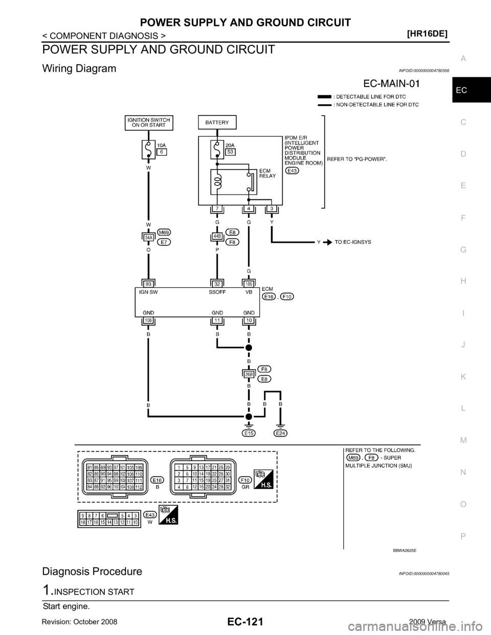
POWER SUPPLY AND GROUND CIRCUIT
Wiring Diagram INFOID:0000000004780556
Diagnosis Procedure INFOID:0000000004780045
Page 1483 of 4331
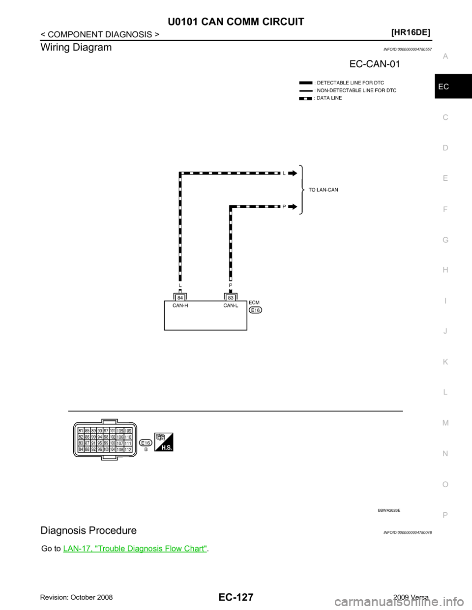
EC
NP
O
Wiring Diagram
INFOID:0000000004780557
Diagnosis Procedure INFOID:0000000004780048
Go to LAN-17, " Trouble Diagnosis Flow Chart " .
Page 1485 of 4331
![NISSAN TIIDA 2009 Service Owners Manual U0140 CAN COMM CIRCUIT
EC-129
< COMPONENT DIAGNOSIS >
[HR16DE] C
D E
F
G H
I
J
K L
M A EC
NP
O
Wiring Diagram
INFOID:0000000004780678
Diagnosis Procedure INFOID:0000000004780051
Go to LAN-17, " Troub NISSAN TIIDA 2009 Service Owners Manual U0140 CAN COMM CIRCUIT
EC-129
< COMPONENT DIAGNOSIS >
[HR16DE] C
D E
F
G H
I
J
K L
M A EC
NP
O
Wiring Diagram
INFOID:0000000004780678
Diagnosis Procedure INFOID:0000000004780051
Go to LAN-17, " Troub](/img/5/57398/w960_57398-1484.png)
U0140 CAN COMM CIRCUIT
EC-129
< COMPONENT DIAGNOSIS >
[HR16DE] C
D E
F
G H
I
J
K L
M A EC
NP
O
Wiring Diagram
INFOID:0000000004780678
Diagnosis Procedure INFOID:0000000004780051
Go to LAN-17, " Trouble Diagnosis Flow Chart " . BBWA2626E