NISSAN TIIDA 2009 Service Manual PDF
TIIDA 2009
NISSAN
NISSAN
https://www.carmanualsonline.info/img/5/57398/w960_57398-0.png
NISSAN TIIDA 2009 Service Manual PDF
Page 1029 of 4331
CVT
N
O P
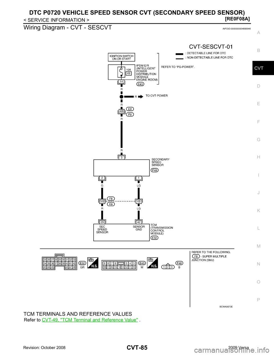
Wiring Diagram - CVT - SESCVT
INFOID:0000000004666946
TCM TERMINALS AND REFERENCE VALUES Refer to CVT-49, " TCM Terminal and Reference Value " .
Page 1037 of 4331
CVT
N
O P
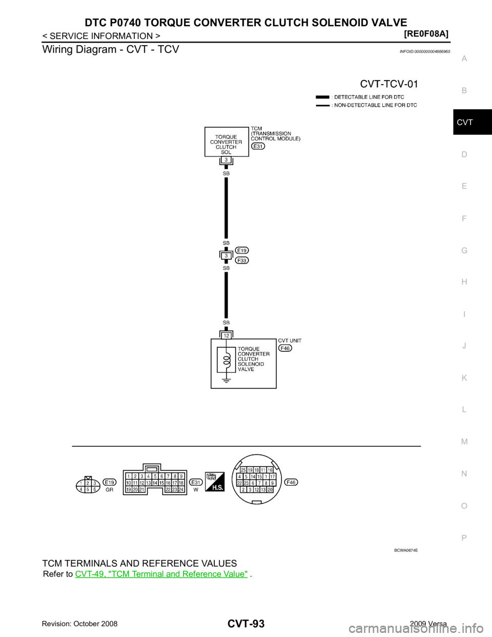
Wiring Diagram - CVT - TCV
INFOID:0000000004666965
TCM TERMINALS AND REFERENCE VALUES Refer to CVT-49, " TCM Terminal and Reference Value " .
Page 1049 of 4331
CVT
N
O P
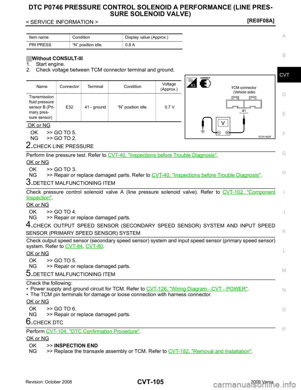
Without CONSULT-III
1. Start engine.
2. Check voltage between TCM connector terminal and ground.
OK or NG OK >> GO TO 5.
NG >> GO TO 2. Inspections before Trouble Diagnosis " .
OK or NG OK >> GO TO 3.
NG >> Repair or replace damaged parts. Refer to CVT-40, " Inspections before Trouble Diagnosis " .
Component
Inspection " .
OK or NG OK >> GO TO 4.
NG >> Repair or replace damaged parts.
4. CHECK OUTPUT SPEED SENSOR (SECONDARY SPEED SENSOR) SYSTEM AND INPUT SPEED ,
CVT-80 .
OK or NG OK >> GO TO 5.
NG >> Repair or replace damaged parts. Wiring Diagram - CVT - POWER " .
• The TCM pin terminals for damage or loose connection with harness connector.
OK or NG OK >> GO TO 6.
NG >> Repair or replace damaged parts. DTC Confirmation Procedure " .
OK or NG OK >>
INSPECTION END
NG >> Replace the transaxle assembly or TCM. Refer to CVT-182, " Removal and Installation " .
Item name Condition Display value (Approx.)
PRI PRESS “N” position idle. 0.8 A Name Connector Terminal Condition
Voltage
(Approx.)
Transmission
fluid pressure
sensor B (Pri-
mary pres-
sure sensor) E32 41 - ground “N” position idle. 0.7 V
Page 1051 of 4331
CVT
N
O P
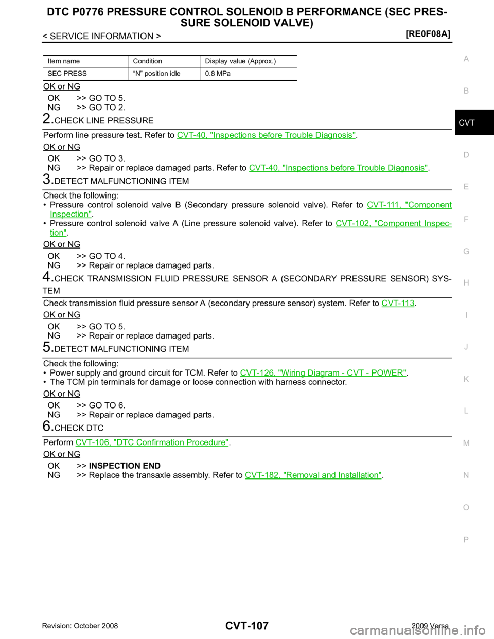
OK or NG OK >> GO TO 5.
NG >> GO TO 2. Inspections before Trouble Diagnosis " .
OK or NG OK >> GO TO 3.
NG >> Repair or replace damaged parts. Refer to CVT-40, " Inspections before Trouble Diagnosis " .
Component
Inspection " .
• Pressure control solenoid valve A (Line pressure solenoid valve). Refer to CVT-102, " Component Inspec-
tion " .
OK or NG OK >> GO TO 4.
NG >> Repair or replace damaged parts.
4. CHECK TRANSMISSION FLUID PRESSURE SENSOR A (SECONDARY PRESSURE SENSOR) SYS- .
OK or NG OK >> GO TO 5.
NG >> Repair or replace damaged parts. Wiring Diagram - CVT - POWER " .
• The TCM pin terminals for damage or loose connection with harness connector.
OK or NG OK >> GO TO 6.
NG >> Repair or replace damaged parts. DTC Confirmation Procedure " .
OK or NG OK >>
INSPECTION END
NG >> Replace the transaxle assembly. Refer to CVT-182, " Removal and Installation " .
Item name Condition Display value (Approx.)
SEC PRESS “N” position idle 0.8 MPa
Page 1053 of 4331
CVT
N
O P
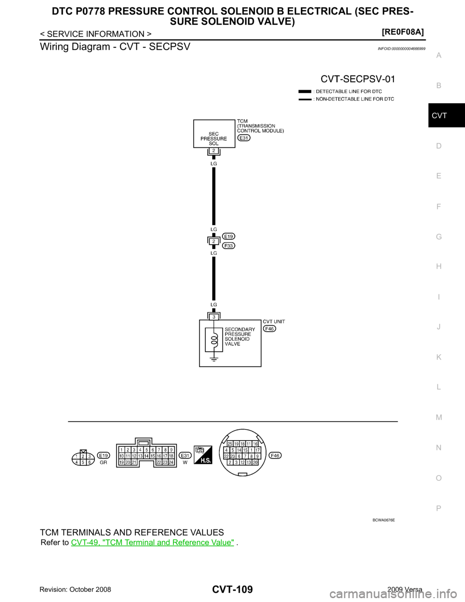
Wiring Diagram - CVT - SECPSV
INFOID:0000000004666999
TCM TERMINALS AND REFERENCE VALUES Refer to CVT-49, " TCM Terminal and Reference Value " .
Page 1068 of 4331
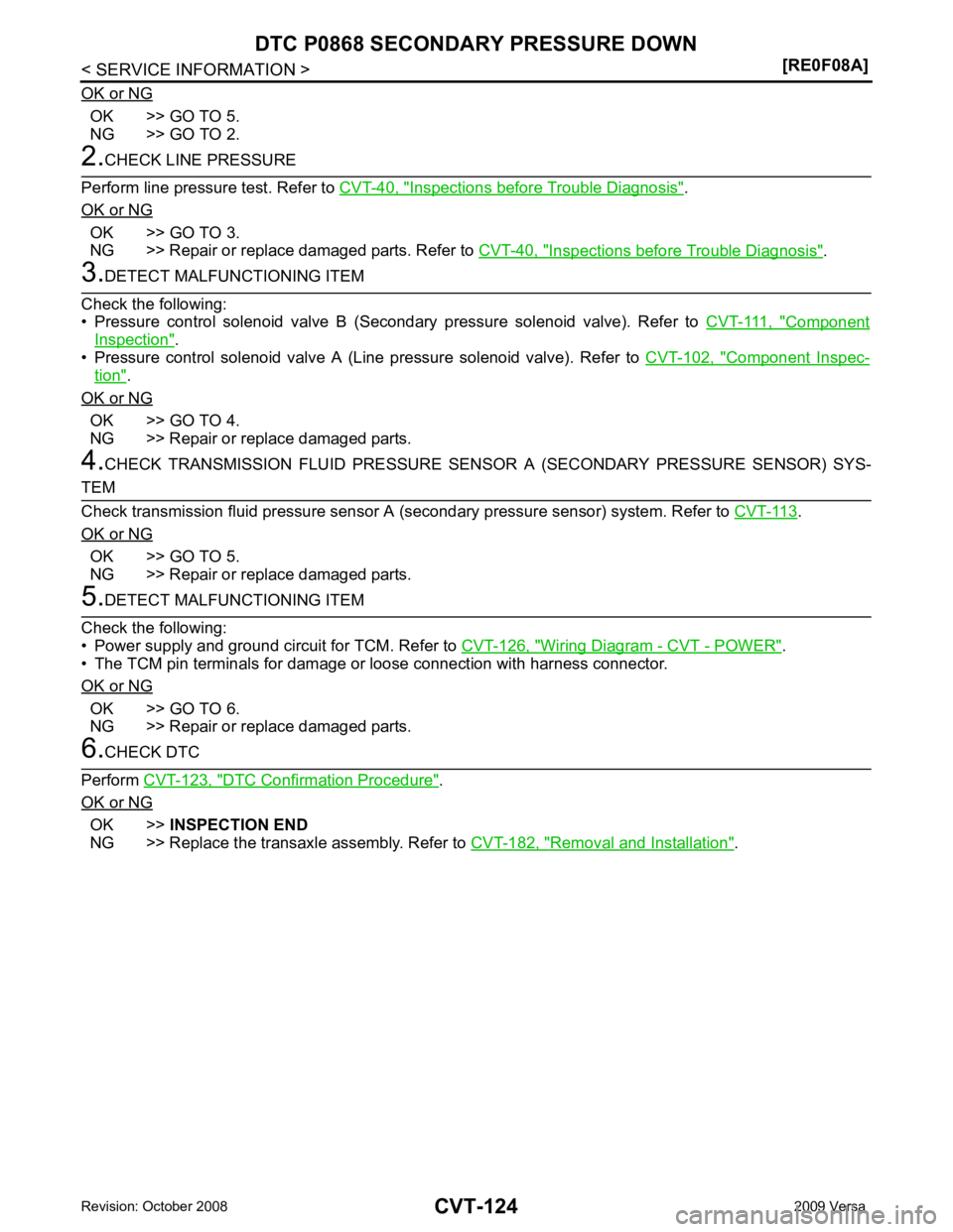
OK >> GO TO 5.
NG >> GO TO 2. Inspections before Trouble Diagnosis " .
OK or NG OK >> GO TO 3.
NG >> Repair or replace damaged parts. Refer to CVT-40, " Inspections before Trouble Diagnosis " .
Component
Inspection " .
• Pressure control solenoid valve A (Line pressure solenoid valve). Refer to CVT-102, " Component Inspec-
tion " .
OK or NG OK >> GO TO 4.
NG >> Repair or replace damaged parts.
4. CHECK TRANSMISSION FLUID PRESSURE SENS OR A (SECONDARY PRESSURE SENSOR) SYS- .
OK or NG OK >> GO TO 5.
NG >> Repair or replace damaged parts. Wiring Diagram - CVT - POWER " .
• The TCM pin terminals for damage or loose connection with harness connector.
OK or NG OK >> GO TO 6.
NG >> Repair or replace damaged parts. DTC Confirmation Procedure " .
OK or NG OK >>
INSPECTION END
NG >> Replace the transaxle assembly. Refer to CVT-182, " Removal and Installation " .
Page 1081 of 4331
CVT
N
O P
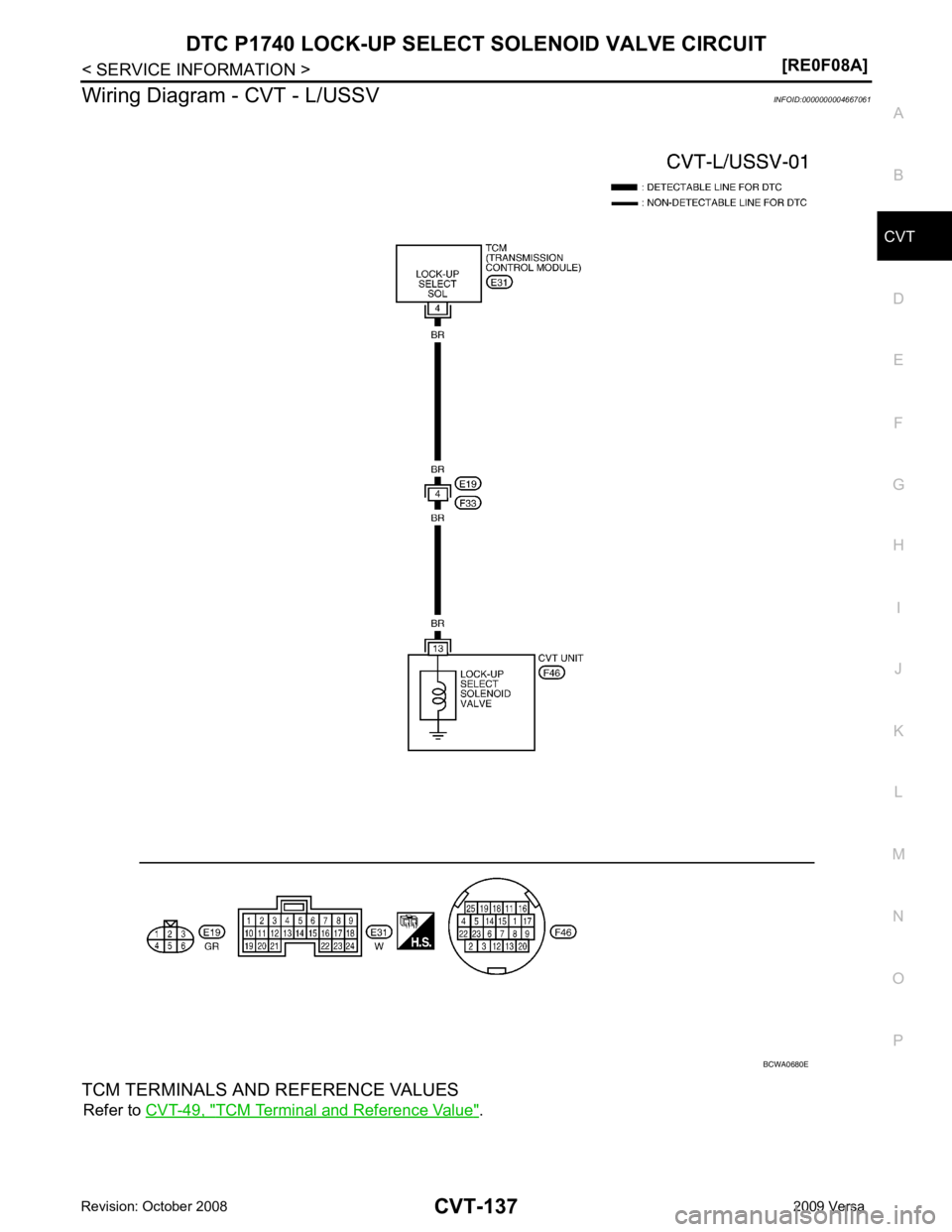
Wiring Diagram - CVT - L/USSV
INFOID:0000000004667061
TCM TERMINALS AND REFERENCE VALUES Refer to CVT-49, " TCM Terminal and Reference Value " .
Page 1097 of 4331
CVT
N
O P
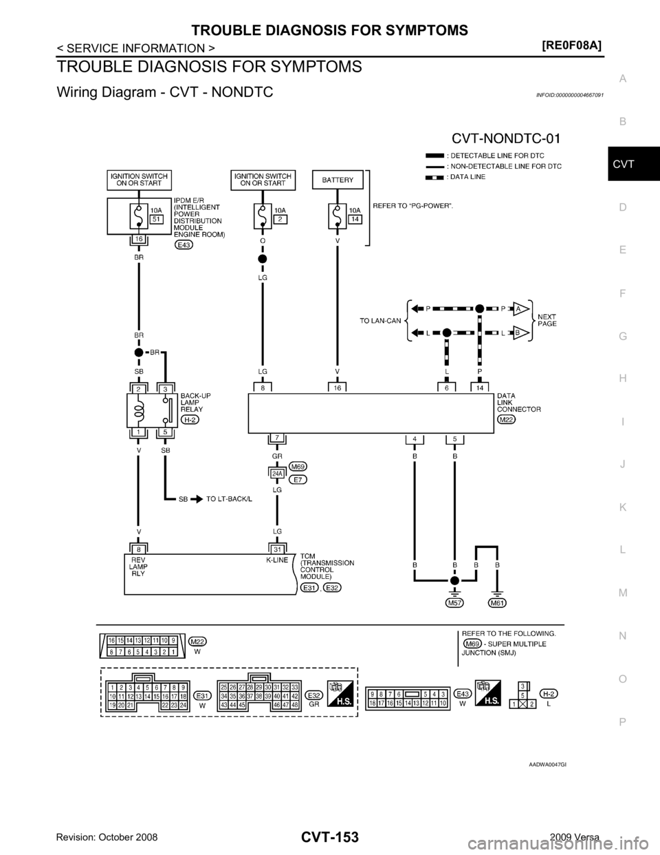
TROUBLE DIAGNOSIS FOR SYMPTOMS
Wiring Diagram - CVT - NONDTC INFOID:0000000004667091 B
Page 1100 of 4331
CONSULT-III Function (TRANSMISSION) " .
Is any malfunction of the “ U1000 CAN COMM CIRCUIT ” indicated in the results?
YES >> Check CAN communication line. Refer to
CVT-60 .
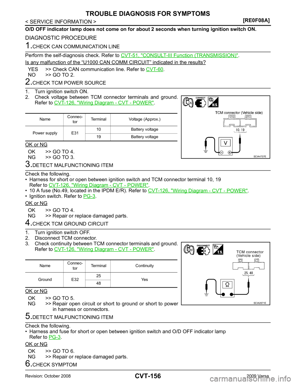
NO >> GO TO 2. Wiring Diagram - CVT - POWER " .
OK or NG OK >> GO TO 4.
NG >> GO TO 3. Wiring Diagram - CVT - POWER " .
• 10 A fuse (No.49, located in the IPDM E/R). Refer to CVT-126, " Wiring Diagram - CVT - POWER " .
• Ignition switch. Refer to PG-3 .
OK or NG OK >> GO TO 4.
NG >> Repair or replace damaged parts. Wiring Diagram - CVT - POWER " .
OK or NG OK >> GO TO 5.
NG >> Repair open circuit or short to ground or short to power
in harness or connectors. .
OK or NG OK >> GO TO 6.
NG >> Repair or replace damaged parts.
Page 1155 of 4331
ON BOARD DIAGNOSTIC (OBD) SYSTEM
CVT-211
< SERVICE INFORMATION >
[RE0F08B] D
E
F
G H
I
J
K L
M A
B CVT
N
O P
The MIL is located on the instrument panel.
1. The MIL will light up when the ignition switch is turned ON with- out the engine running. This is a bulb check.
• If the MIL does not light up, refer to DI-20, " Schematic " , or see
EC-1532, " Wiring Diagram " .
2. When the engine is start ed, the MIL should go off.
If the MIL remains on, the on board diagnostic system has
detected an engine system malfunction. SEF217U

![NISSAN TIIDA 2009 Service Manual PDF ON BOARD DIAGNOSTIC (OBD) SYSTEM
CVT-211
< SERVICE INFORMATION >
[RE0F08B] D
E
F
G H
I
J
K L
M A
B CVT
N
O P
The MIL is located on the instrument panel.
1. The MIL will light up when the ignition swit NISSAN TIIDA 2009 Service Manual PDF ON BOARD DIAGNOSTIC (OBD) SYSTEM
CVT-211
< SERVICE INFORMATION >
[RE0F08B] D
E
F
G H
I
J
K L
M A
B CVT
N
O P
The MIL is located on the instrument panel.
1. The MIL will light up when the ignition swit](/img/5/57398/w960_57398-1154.png)