brake light NISSAN TIIDA 2009 Service User Guide
[x] Cancel search | Manufacturer: NISSAN, Model Year: 2009, Model line: TIIDA, Model: NISSAN TIIDA 2009Pages: 4331, PDF Size: 58.04 MB
Page 1288 of 4331
![NISSAN TIIDA 2009 Service User Guide CVT-344< SERVICE INFORMATION >
[RE0F08B]
SHIFT CONTROL SYSTEM
• When installing the control cable (1) to the control device assembly (2), make sure that the control cable (1) is fully pressed in wit](/img/5/57398/w960_57398-1287.png "NISSAN TIIDA 2009 Service User Guide CVT-344< SERVICE INFORMATION >
[RE0F08B]
SHIFT CONTROL SYSTEM
• When installing the control cable (1) to the control device assembly (2), make sure that the control cable (1) is fully pressed in wit")
CVT-344< SERVICE INFORMATION >
[RE0F08B]
SHIFT CONTROL SYSTEM
• When installing the control cable (1) to the control device assembly (2), make sure that the control cable (1) is fully pressed in with the
ribbed surface (A) facing downward from the vehicle.
: Vehicle front
• After installation is completed, adjust and check the CVT position.
Refer to CVT-345, " Adjustment of CVT Position " and
CVT-345, " Checking of CVT Position " .
Control Device Disassembly and Assembly INFOID:0000000004305817
DISASSEMBLY
NOTE:
Refer to CVT-341, " Removal and Installation " to disassemble.
1. Remove selector lever knob from control device assembly. Refer to CVT-344, " Selector Lever Knob
Removal and Installation " .
2. Remove position lamp from position indicator plate (1).
3. Insert a suitable tool to (A) (at 4 locations) as shown, and bend each hook slightly to raise position indicator plate (1) and
remove from control device assembly (2).
4. Remove bracket from control device assembly (2).
5. Remove CVT device harness c onnector from control device
assembly (2).
6. Release tabs (A) on shift lock solenoid and park position switch assembly from hooks (B) on control device assembly to shift
lock solenoid and park position switch assembly.
ASSEMBLY
Assembly is in the reverse order of disassembly.
Selector Lever Knob Re moval and Installation INFOID:0000000004305818
REMOVAL
CAUTION:
Make sure that parking brake is applied before removal/installation. SCIA6253E
SCIA6969E
SCIA6977E
Page 1303 of 4331

DI
N
O P
CONTENTS
DRIVER INFORMATION SYSTEM
SERVICE INFORMATION .. ..........................2
PRECAUTION ................................................ .....2
Precaution for Supplemental Restraint System
(SRS) "AIR BAG" and "SEAT BELT PRE-TEN-
SIONER" ............................................................. ......
2
COMBINATION METERS .............................. .....3
Component Parts and Harness Connector Loca-
tion ...................................................................... ......
3
System Description ............................................. ......3
Arrangement of Combination Meter .................... ......5
Internal Circuit ..................................................... ......6
Wiring Diagram - METER - ................................. ......7
Combination Meter Harness Connector Terminal
Layout ................................................................. ......
9
Terminal and Reference Value for Combination
Meter ................................................................... ......
9
Self-Diagnosis Mode of Combination Meter ........ ....10
CONSULT-III Function (METER/M&A) ............... ....12
Trouble Diagnosis ............................................... ....13
Symptom Chart ................................................... ....14
Power Supply and Ground Circuit Inspection ..... ....14
Vehicle Speed Signal Inspection ......................... ....15
Engine Speed Signal Inspection ......................... ....16
Fuel Level Sensor Signal Inspection ................... ....16
Fuel Gauge Fluctuates, Indicates Wrong Value, or
Varies .................................................................. ....
18
Fuel Gauge Does Not Move to Full-position ...........18
DTC [U1000] CAN Communication Circuit ......... ....18
Electrical Component Inspection ......................... ....19
Removal and Installation .........................................19
WARNING LAMPS ......................................... ....20
Schematic ........................................................... ....20
Wiring Diagram - WARN - ................................... ....21 Oil Pressure Wa
rning Lamp Stays Off (Ignition
Switch ON) .......................................................... ....
29
Oil Pressure Wa rning Lamp Does Not Turn Off
(Oil Pressure Is Normal) ...................................... ....
31
Component Inspection ......................................... ....31
A/T INDICATOR ................................................ 33
System Description .............................................. ....33
Wiring Diagram - AT/IND - ................................... ....34
A/T Indicator Does Not Illuminate ........................ ....35
CVT INDICATOR ............................................... 37
System Description .............................................. ....37
Schematic ............................................................ ....37
Wiring Diagram - CVTIND - ................................. ....38
CVT Indicator Does Not Illuminate ...................... ....40
WARNING CHIME ............................................. 42
Component Parts and Harness Connector Loca-
tion ....................................................................... ....
42
System Description .............................................. ....42
Wiring Diagram - CHIME - ................................... ....45
Terminal and Reference Value for BCM ..................46
CONSULT-III Function (B CM) .................................46
Trouble Diagnosis ................................................ ....47
Combination Meter Buzzer Cir cuit Inspection .........48
Front Door Switch LH Signal Inspection .............. ....49
Key Switch Signal Inspec tion (Without Intelligent
Key) ..................................................................... ....
50
Key Switch and Ignition Knob Switch Signal In-
spection (With Intelligent Key, When Mechanical
Key Is Used) ........................................................ ....
51
Lighting Switch Signal Inspection ........................ ....53
Parking Brake Switch Signal Inspection .............. ....53
Electrical Component Inspection ......................... ....54
Page 1350 of 4331
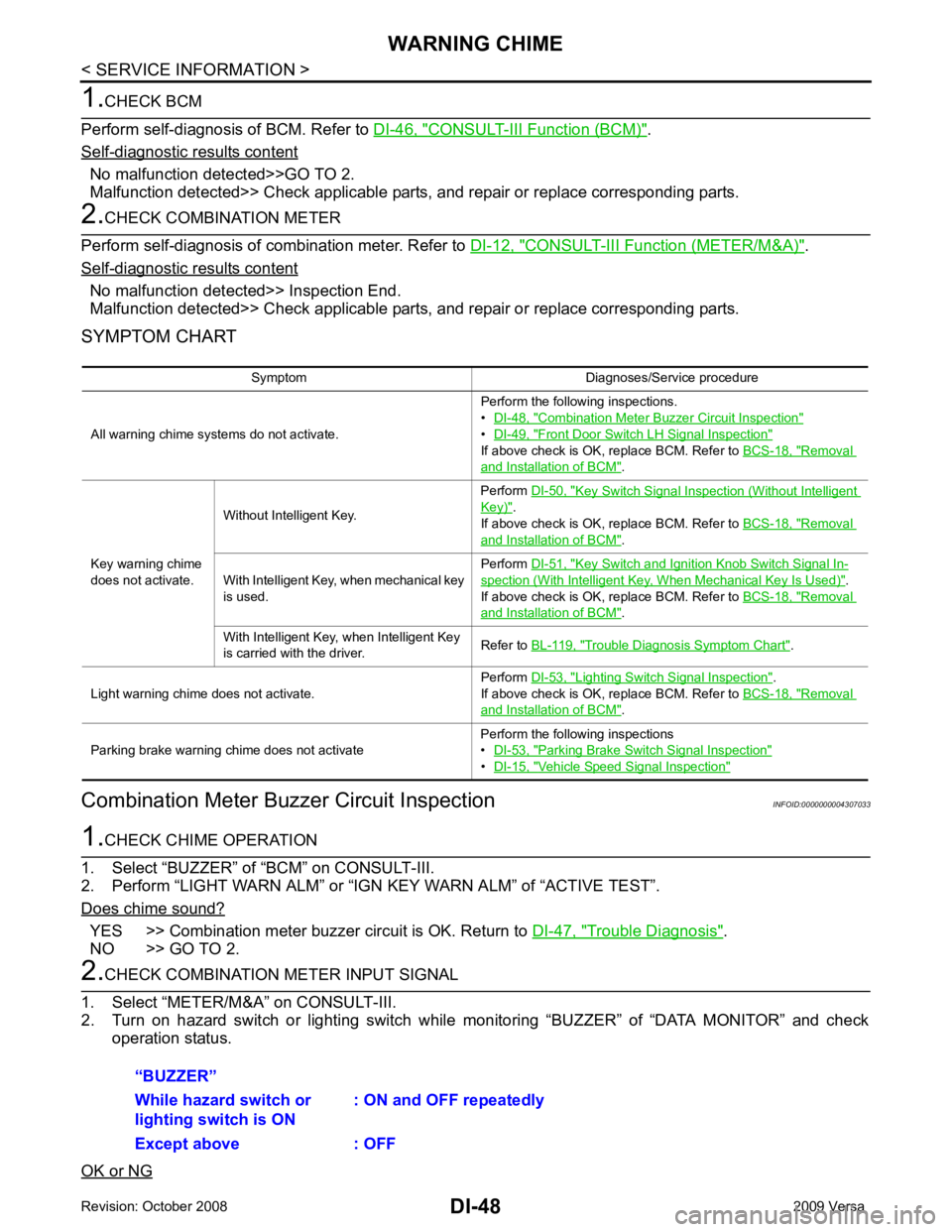
CONSULT-III Function (BCM) " .
Self - diagnostic results content
No malfunction detected>>GO TO 2.
Malfunction detected>> Check applicable parts, and repair or replace corresponding parts. CONSULT-III Function (METER/M&A) " .
Self - diagnostic results content
No malfunction detected>> Inspection End.
Malfunction detected>> Check applicable parts, and repair or replace corresponding parts.
SYMPTOM CHART
Combination Meter Buzzer Circuit Inspection INFOID:0000000004307033YES >> Combination meter buzzer circuit is OK. Return to
DI-47, " Trouble Diagnosis " .
NO >> GO TO 2. Combination Meter Buzzer Circuit Inspection "
•
DI-49, " Front Door Switch LH Signal Inspection "
If above check is OK, replace BCM. Refer to
BCS-18, " Removal
and Installation of BCM " .
Key warning chime
does not activate. Without Intelligent Key.
Perform
DI-50, " Key Switch Signal Inspection (Without Intelligent
Key) " .
If above check is OK, replace BCM. Refer to BCS-18, " Removal
and Installation of BCM " .
With Intelligent Key, when mechanical key
is used. Perform
DI-51, " Key Switch and Ignition Knob Switch Signal In-
spection (With Intelligent Key, When Mechanical Key Is Used) " .
If above check is OK, replace BCM. Refer to BCS-18, " Removal
and Installation of BCM " .
With Intelligent Key, when Intelligent Key
is carried with the driver. Refer to
BL-119, " Trouble Diagnosis Symptom Chart " .
Light warning chime does not activate. Perform
DI-53, " Lighting Switch Signal Inspection " .
If above check is OK, replace BCM. Refer to BCS-18, " Removal
and Installation of BCM " .
Parking brake warning chime does not activate Perform the following inspections
• DI-53, " Parking Brake Switch Signal Inspection "
•
DI-15, " Vehicle Speed Signal Inspection "
Page 1355 of 4331
DI
N
O P
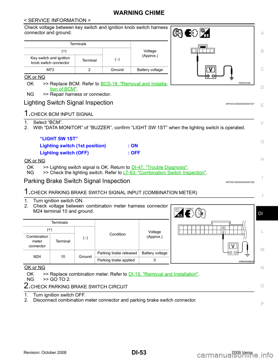
Check voltage between key switch and ignition knob switch harness
connector and ground.
OK or NG OK >> Replace BCM. Refer to
BCS-18, " Removal and Installa-
tion of BCM " .
NG >> Repair harness or connector.
Lighting Switch Signal Inspection INFOID:0000000004307037OK >> Lighting switch signal is OK. Return to
DI-47, " Trouble Diagnosis " .
NG >> Check the lighting switch. Refer to LT-63, " Combination Switch Inspection " .
Parking Brake Switch Signal Inspection INFOID:0000000004307038OK >> Replace combination meter. Refer to
DI-19, " Removal and Installation " .
NG >> GO TO 2. B
Page 1463 of 4331

EC
NP
O
HO2S2 (B1) V
• The signal voltage of the heated oxygen sensor 2 is
displayed.
HO2S2 MNTR(B1) RICH/
LEAN • Display of heated oxygen sensor 2 signal:
RICH: means the amount of oxygen after three way
catalyst is relatively small.
LEAN: means the amount of oxygen after three way
catalyst is relatively large. • When the engine is stopped, a certain
value is indicated.
VHCL SPEED SE km/h or
mph • The vehicle speed computed from the vehicle speed
signal sent from combination meter is displayed.
BATTERY VOLT V • The power supply voltage of ECM is displayed.
ACCEL SEN 1 V• The accelerator pedal position sensor signal voltage is
displayed. • ACCEL SEN 2 signal is converted by
ECM internally. Thus, it differs from
ECM terminal voltage signal.
ACCEL SEN 2
TP SEN 1-B1 V• The throttle position sensor signal voltage is dis-
played. • TP SEN 2-B1 signal is converted by
ECM internally. Thus, it differs from
ECM terminal voltage signal.
TP SEN 2-B1
FUEL T/TMP SE °C or °F • The fuel temperature (determined by the signal volt-
age of the fuel tank temperature sensor) is displayed.
INT/A TEMP SE °C or °F • The intake air temperature (determined by the signal
voltage of the intake air temperature sensor) is indicat-
ed.
EVAP SYS PRES V • The signal voltage of EVAP control system pressure
sensor is displayed.
FUEL LEVEL SE V • The signal voltage of the fuel level sensor is displayed.
START SIGNAL ON/OFF • Indicates start signal status [ON/OFF] computed by
the ECM according to the signals of engine speed and
battery voltage. • After starting the engine, [OFF] is dis-
played regardless of the starter sig-
nal.
CLSD THL POS ON/OFF • Indicates idle position [ON/OFF] computed by ECM
according to the accelerator pedal position sensor sig-
nal.
AIR COND SIG ON/OFF • Indicates [ON/OFF] condition of the air conditioner
switch determined by the air conditioner ON signal.
P/N POSI SW ON/OFF • Indicates [ON/OFF] condit
ion from the park/neutral
position (PNP) switch signal.
PW/ST SIGNAL ON/OFF • [ON/OFF] condition of the power steering system (de-
termined by the signal sent from EPS control unit) is
indicated.
LOAD SIGNAL ON/OFF • Indicates [ON/OFF] condition from the electrical load
signal.
ON: Rear window defogger switch is ON and/or light-
ing switch is in 2nd position.
OFF: Both rear window defogger switch and lighting
switch are OFF.
IGNITION SW ON/OFF • Indicates [ON/OFF] condition from ignition switch sig-
nal.
HEATER FAN SW ON/OFF • Indicates [ON/OFF] condition from the heater fan
switch signal.
BRAKE SW ON/OFF • Indicates [ON/OFF] condition from the stop lamp
switch signal.
INJ PULSE-B1 msec • Indicates the actual fuel injection pulse width compen-
sated by ECM according to the input signals. • When the engine is stopped, a certain
computed value is indicated.
IGN TIMING BTDC • Indicates the ignition timing computed by ECM ac-
cording to the input signals. • When the engine is stopped, a certain
value is indicated.
CAL/LD VALUE % • “Calculated load value” indicates the value of the cur-
rent air flow divided by peak air flow.
Monitored item Unit Description Remarks
Page 1738 of 4331
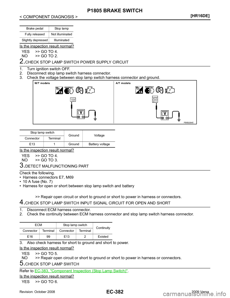
YES >> GO TO 4.
NO >> GO TO 2. YES >> GO TO 4.
NO >> GO TO 3. YES >> GO TO 5.
NO >> Repair open circuit or short to ground or short to power in harness or connectors. Component Inspection (Stop Lamp Switch) " .
Is the inspection result normal? YES >> GO TO 6.Brake pedal Stop lamp
Fully released Not illuminated
Slightly depressed Illuminated Stop lamp switch
Ground Voltage
Connector Terminal
E13 1 Ground Battery voltage
Page 1739 of 4331
EC
NP
O
NO >> Replace stop lamp switch. Diagnosis Procedure " .
>> INSPECTION END
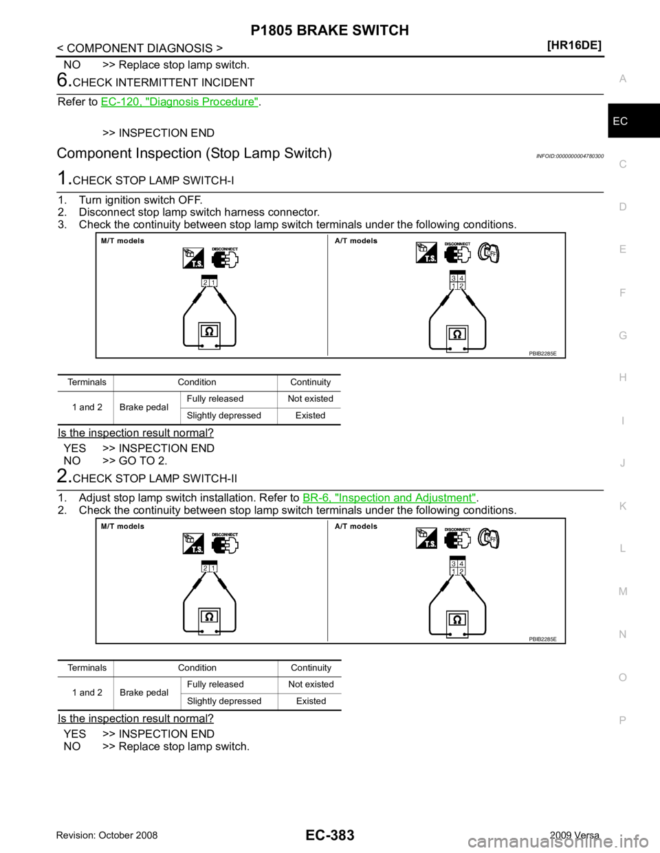
Component Inspection (Stop Lamp Switch) INFOID:0000000004780300YES >> INSPECTION END
NO >> GO TO 2. Inspection and Adjustment " .
2. Check the continuity between stop lamp switch terminals under the following conditions.
Is the inspection result normal? YES >> INSPECTION END
NO >> Replace stop lamp switch. Terminals Condition Continuity
1 and 2 Brake pedal Fully released Not existed
Slightly depressed Existed
Page 1825 of 4331
![NISSAN TIIDA 2009 Service User Guide EC
NP
O
73 P
Intake valve timing control
solenoid valve [Engine is running]
• Warm-up condition
• Idle speed BATTERY VOLTAGE
(11 - 14 V)
[Engine is running]
• Warm-up condition
• When revving](/img/5/57398/w960_57398-1824.png "NISSAN TIIDA 2009 Service User Guide EC
NP
O
73 P
Intake valve timing control
solenoid valve [Engine is running]
• Warm-up condition
• Idle speed BATTERY VOLTAGE
(11 - 14 V)
[Engine is running]
• Warm-up condition
• When revving")
EC
NP
O
73 P
Intake valve timing control
solenoid valve [Engine is running]
• Warm-up condition
• Idle speed BATTERY VOLTAGE
(11 - 14 V)
[Engine is running]
• Warm-up condition
• When revving engine up to 2,000 rpm quick- ly 7 - 10 V
74 W Sensor power supply
(Refrigerant pressure
sensor) [Ignition switch: ON]
Approximately 5 V
75 BR Sensor power supply
[Crankshaft position sensor
(POS)] [Ignition switch: ON]
Approximately 5 V
76 W EVAP control system pres-
sure sensor power supply [Ignition switch: ON]
Approximately 5 V
78 O Sensor power supply
[Camshaft position sensor
(PHASE)] [Ignition switch: ON]
Approximately 5 V
83 P CAN communication line — —
84 L CAN communication line — —
88 LG DATA link connector — —
93 O Ignition switch [Ignition switch: OFF]
0V
[Ignition switch: ON] BATTERY VOLTAGE
(11 - 14 V)
99 R Stop lamp switch [Ignition switch: OFF]
• Brake pedal: Fully released Approximately 0 V
[Ignition switch: OFF]
• Brake pedal: Slightly depressed BATTERY VOLTAGE
(11 - 14 V)
102 SB Sensor power supply
(Accelerator pedal position
sensor 2) [Ignition switch: ON]
Approximately 5 V
103 GR Accelerator pedal position
sensor 2 [Ignition switch: ON]
• Engine stopped
• Accelerator pedal: Fully released 0.3 - 0.6 V
[Ignition switch: ON]
• Engine stopped
• Accelerator pedal: Fully depressed 1.95 - 2.4 V
104 Y Sensor ground
(Accelerator pedal position
sensor 2) [Engine is running]
• Warm-up condition
• Idle speed Approximately 0 V
105 G Power supply for ECM [Ignition switch: ON]BATTERY VOLTAGE
(11 - 14 V)
106 P Sensor power supply
(Accelerator pedal position
sensor 1) [Ignition switch: ON]
Approximately 5 V
108 B ECM ground [Engine is running]
• Idle speed Body ground
TERMI-
NAL
NO. WIRE
COLOR ITEM CONDITION DATA (DC Voltage)
Page 1829 of 4331

EC
NP
O
DTC RELATED ITEM
Detected items
Engine operating condition in
fail-safe mode Remarks
Malfunction indicator
lamp circuit Engine speed will not rise
more than 2,500 rpm due to
the fuel cut When there is an open circuit on MIL circuit, the ECM cannot warn the driver by
lighting up MIL when there is malfunction on engine control system.
Therefore, when electrical controlled throttle and part of ECM related diagnoses
are continuously detected as NG for 5 trips, ECM warns the driver that engine
control system malfunctions and MIL circuit is open by means of operating fail-
safe function.
The fail-safe function also operates when above diagnoses except MIL circuit
are detected and demands the driver to repair the malfunction. DTC No. Detected items Engine operating condition in fail-safe mode
P0011 Intake valve timing control The signal is not energized to the intake valve timing control solenoid valve and the valve control does not function.
P0102
P0103 Mass air flow sensor circuit Engine speed will not rise more than 2,400 rpm due to the fuel cut.
P0117
P0118 Engine coolant tempera-
ture sensor circuit Engine coolant temperature will be determined by ECM based on the following condition.
CONSULT-III displays the engine coolant temperature decided by ECM.
Condition Engine coolant temperature decided
(CONSULT-III display)
Just as ignition switch is turned ON
or START 40
°C (104 °F)
More than approx. 4 minutes after
engine starting 80
°C (176 °F)
Except as shown above 40 - 80
°C (104 - 176 °F)
(Depends on the time)
When the fail-safe system for engine coolant temperature sensor is activated, the cooling
fan operates while engine is running.
P0122
P0123
P0222
P0223
P2135 Throttle position sensor The ECM controls the electric throttle control actuator in regulating the throttle opening in
order for the idle position to be within +10 degrees.
The ECM regulates the opening speed of the throttle valve to be slower than the normal
condition.
So, the acceleration will be poor.
P0643 Sensor power supply ECM stops the electric throttle control actuator control, throttle valve is maintained at a fixed opening (approx. 5 degrees) by the return spring.
P0605 ECM (When ECM calculation function is malfunctioning:) ECM stops the electric throttle control actuator control, throttle valve is maintained at a
fixed opening (approx. 5 degrees) by the return spring.
P1805 Brake switch ECM controls the electric throttle control actuator by regulating the throttle opening to a small range.
Therefore, acceleration will be poor.
Vehicle condition Driving condition
When engine is idling Normal
When accelerating Poor acceleration
P2100
P2103 Throttle control motor relay ECM stops the electric throttle control actuator control, throttle valve is maintained at a
fixed opening (approx. 5 degrees) by the return spring.
P2101 Electric th rottle control
function ECM stops the electric throttle control actuator control, throttle valve is maintained at a
fixed opening (approx. 5 degrees) by the return spring.
P2118 Throttle control motor ECM stops the electric throttle control actuator control, throttle valve is maintained at a fixed opening (approx. 5 degrees) by the return spring.
Page 1900 of 4331

(A/T),
CVT-258 (CVT)
ENGINE SPEED SIG P0725 0725 — 2 ×CVT-263 A/T 1ST GR FNCTN P0731 0731 — 2
×AT-110 A/T 2ND GR FNCTN P0732 0732 — 2
×AT-113 A/T 3RD GR FNCTN P0733 0733 — 2
×AT-116 A/T 4TH GR FNCTN P0734 0734 — 2
×AT-119 TCC SOLENOID/CIRC P0740 0740 — 2
×AT-124 A/T TCC S/V FNCTN P0744 0744 — 2
×AT-129 (A/T),
CVT-271 (CVT)
L/PRESS SOL/CIRC P0745 0745 — 2 ×CVT-273 PRS CNT SOL/A FCTN P0746 0746 — 1
×CVT-278 SFT SOL A/CIRC P0750 0750 — 1
×AT-139 SFT SOL B/CIRC P0755 0755 — 1
×AT-144 PRS CNT SOL/B FCTN P0776 0776 — 2
×CVT-280 PRS CNT SOL/B CIRC P0778 0778 — 2
×CVT-282 TR PRS SENS/A CIRC P0840 0840 — 2
×CVT-287 TR PRS SENS/B CIRC P0845 0845 — 2
×CVT-119 P-N POS SW/CIRCUIT P0850 0850 — 2
×EC-879 CLOSED LOOP-B1 P1148 1148 — 1
×EC-885 ENG OVER TEMP P1217 1217 — 1
×EC-886 CTP LEARNING-B1 P1225 1225 — 2 —
EC-895CTP LEARNING-B1 P1226 1226 — 2 —
EC-897COLD START CONTROL P1421 1421 — 2
×EC-899 ASCD SW P1564 1564 — 1 —
EC-901ASCD BRAKE SW P1572 1572 — 1 —
EC-907ASCD VHL SPD SEN P1574 1574 — 1 —
EC-916LOCK MODE P1610 1610 — 2 —
BL-259ID DISCORD,IMMU-ECM P1611 1611 — 2 —
BL-259CHAIN OF ECM-IMMU P1612 1612 — 2 —
BL-259CHAIN OF IMMU-KEY P1614 1614 — 2 —
BL-259DIFFERENCE OF KEY P1615 1615 — 2 —
BL-259TP SEN/CIRC A/T P1705 1705 — 1
×CVT-299 IN PULY SPEED P1715 1715 — 2 —
EC-918 (A/T),
EC-919 (CVT)
LU-SLCT SOL/CIRC P1740 1740 — 2 ×CVT-306 O/R CLTCH SOL/CIRC P1760 1760 — 2
×AT-149 STEP MOTR CIRC P1777 1777 — 1
×CVT-311 STEP MOTR FNC P1778 1778 — 2
×CVT-315 BRAKE SW/CIRCUIT P1805 1805 — 2 —
EC-921ETC MOT PWR-B1 P2100 2100 — 1
×EC-925 ETC FNCTN/CIRC-B1 P2101 2101 — 1
×EC-929 ETC MOT PWR P2103 2103 — 1
×EC-925 Items
(CONSULT-III screen terms) DTC*
1
SRT code Trip MIL lighting up Reference page
CONSULT-III
GST* 2
ECM*3