air condition NISSAN TIIDA 2009 Service Owner's Manual
[x] Cancel search | Manufacturer: NISSAN, Model Year: 2009, Model line: TIIDA, Model: NISSAN TIIDA 2009Pages: 4331, PDF Size: 58.04 MB
Page 162 of 4331
AT
N
O P
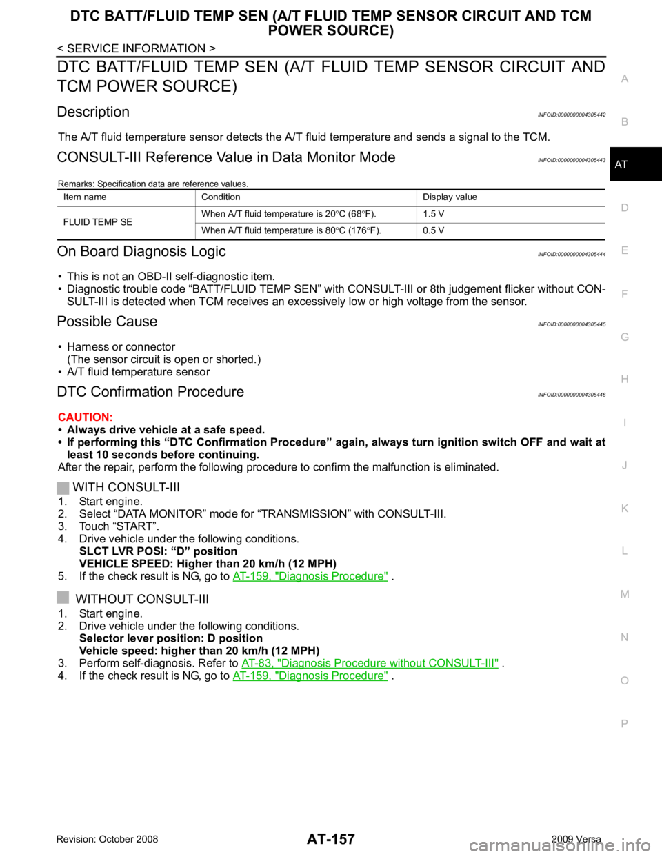
DTC BATT/FLUID TEMP SEN (A/T FL
UID TEMP SENSOR CIRCUIT AND
TCM POWER SOURCE)
Description INFOID:0000000004305442
The A/T fluid temperature sensor detects the A/ T fluid temperature and sends a signal to the TCM.
CONSULT-III Reference Val ue in Data Monitor Mode INFOID:0000000004305443
Remarks: Specification data are reference values.
On Board Diagnosis Logic INFOID:0000000004305444
• This is not an OBD-II self-diagnostic item.
• Diagnostic trouble code “BATT/FLUID TEMP SEN” with CONSULT-III or 8th judgement flicker without CON-
SULT-III is detected when TCM receives an exce ssively low or high voltage from the sensor.
Possible Cause INFOID:0000000004305445
• Harness or connector (The sensor circuit is open or shorted.)
• A/T fluid temperature sensor
DTC Confirmation Procedure INFOID:0000000004305446
CAUTION:
• Always drive vehicle at a safe speed.
• If performing this “DTC Confirmation Procedure” again, always turn ignition switch OFF and wait at
least 10 seconds before continuing.
After the repair, perform the following procedure to confirm the malfunction is eliminated.
WITH CONSULT-III
1. Start engine.
2. Select “DATA MONITOR” mode for “TRANSMISSION” with CONSULT-III.
3. Touch “START”.
4. Drive vehicle under the following conditions. SLCT LVR POSI: “D” position
VEHICLE SPEED: Higher than 20 km/h (12 MPH)
5. If the check result is NG, go to AT-159, " Diagnosis Procedure " .
WITHOUT CONSULT-III
1. Start engine.
2. Drive vehicle under the following conditions. Selector lever position: D position
Vehicle speed: higher than 20 km/h (12 MPH)
3. Perform self-diagnosis. Refer to AT-83, " Diagnosis Procedure without CONSULT-III " .
4. If the check result is NG, go to AT-159, " Diagnosis Procedure " .
Item name Condition Display value
FLUID TEMP SE When A/T fluid temperature is 20
°C (68 °F). 1.5 V
When A/T fluid temperature is 80 °C (176 °F). 0.5 V
Page 165 of 4331
AT-160< SERVICE INFORMATION >
DTC BATT/FLUID TEMP SEN (A/T FLU
ID TEMP SENSOR CIRCUIT AND TCM
POWER SOURCE)
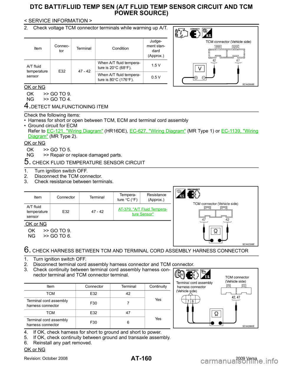
2. Check voltage TCM connector terminals while warming up A/T.
OK or NG OK >> GO TO 9.
NG >> GO TO 4. 4.
DETECT MALFUNCTIONING ITEM
Check the following items:
• Harness for short or open between TCM, ECM and terminal cord assembly
• Ground circuit for ECM
Refer to EC-121, " Wiring Diagram " (HR16DE),
EC-627, " Wiring Diagram " (MR Type 1) or
EC-1139, " Wiring
Diagram " (MR Type 2).
OK or NG OK >> GO TO 5.
NG >> Repair or replace damaged parts. 5.
CHECK FLUID TEMPERATURE SENSOR CIRCUIT
1. Turn ignition switch OFF.
2. Disconnect the TCM connector.
3. Check resistance between terminals.
OK or NG OK >> GO TO 9.
NG >> GO TO 6. 6.
CHECK HARNESS BETWEEN TCM AND TERM INAL CORD ASSEMBLY HARNESS CONNECTOR
1. Turn ignition switch OFF.
2. Disconnect terminal cord assembly harness connector and TCM connector.
3. Check continuity between terminal cord assembly harness con-
nector terminal and TCM connector terminal.
4. If OK, check harness for short to ground and short to power.
5. If OK, check continuity bet ween ground and transaxle assembly.
6. Reinstall any part removed.
OK or NG Item
Connec-
tor Terminal Condition Judge-
ment stan-
dard
(Approx.)
A/T fluid
temperature
sensor E32 47 - 42 When A/T fluid tempera-
ture is 20 °C (68 °F). 1.5 V
When A/T fluid tempera-
ture is 80 °C (176 °F). 0.5 V SCIA2658E
Item Connector Terminal
Tempera-
ture °C ( °F) Resistance
(Approx.)
A/T fluid
temperature
sensor E32 47 - 42
AT-379, " A/T Fluid Tempera-
ture Sensor "
SCIA2338E
Item Connector Terminal Continuity
TCM E32 42 Yes
Terminal cord assembly
harness connector F30 7
TCM E32 47 Yes
Terminal cord assembly
harness connector F30 6 SCIA2660E
Page 168 of 4331
AT
N
O P
DTC TURBINE REVOLUTION SENSOR
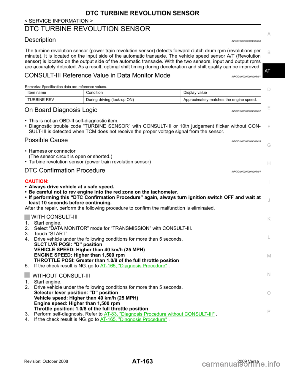
Description INFOID:0000000004305450
The turbine revolution sensor (power train revolution s ensor) detects forward clutch drum rpm (revolutions per
minute). It is located on the input side of the automat ic transaxle. The vehicle speed sensor A/T (Revolution
sensor) is located on the output side of the automatic transaxle. With the two sensors, input and output rpms
are accurately detected. As a resu lt, optimal shift timing during deceleration and shift quality can be improved.
CONSULT-III Reference Val ue in Data Monitor Mode INFOID:0000000004305451
Remarks: Specification data are reference values.
On Board Diagnosis Logic INFOID:0000000004305452
• This is not an OBD-II self-diagnostic item.
• Diagnostic trouble code “TURBINE SENSOR” with CO NSULT-III or 10th judgement flicker without CON-
SULT-III is detected when TCM does not receiv e the proper voltage signal from the sensor.
Possible Cause INFOID:0000000004305453
• Harness or connector (The sensor circuit is open or shorted.)
• Turbine revolution sensor (power train revolution sensor)
DTC Confirmation Procedure INFOID:0000000004305454
CAUTION:
• Always drive vehicle at a safe speed.
• Be careful not to rev engine into the red zone on the tachometer.
• If performing this “DTC Confirmation Procedure” again, always turn ignition switch OFF and wait at
least 10 seconds before continuing.
After the repair, perform the following procedure to confirm the malfunction is eliminated.
WITH CONSULT-III
1. Start engine.
2. Select “DATA MONITOR” mode for “TRANSMISSION” with CONSULT-III.
3. Touch “START”.
4. Drive vehicle under the following conditions for more than 5 seconds. SLCT LVR POSI: “D” position
VEHICLE SPEED: Higher than 40 km/h (25 MPH)
ENGINE SPEED: Higher than 1,500 rpm
THROTTLE POSI: Greater than 1.0/ 8 of the full throttle position
5. If the check result is NG, go to AT-165, " Diagnosis Procedure " .
WITHOUT CONSULT-III
1. Start engine.
2. Drive vehicle under the following conditions for more than 5 seconds. Selector lever posi tion: “D” position
Vehicle speed: Higher than 40 km/h (25 MPH)
Engine speed: Higher than 1,500 rpm
Throttle position: 1.0/8 of the full throttle position
3. Perform self-diagnosis. Refer to AT-83, " Diagnosis Procedure without CONSULT-III " .
4. If the check result is NG, go to AT-165, " Diagnosis Procedure " .
Item name Condition Display value
TURBINE REV During driving (lock-up ON) Approximately matches the engine speed.
Page 179 of 4331
AT-174< SERVICE INFORMATION >
PNP, OD SWITCH AND CLOSED THRO
TTLE, WIDE OPEN THROTTLE POSI-
TION SIGNAL CIRCUIT 4.
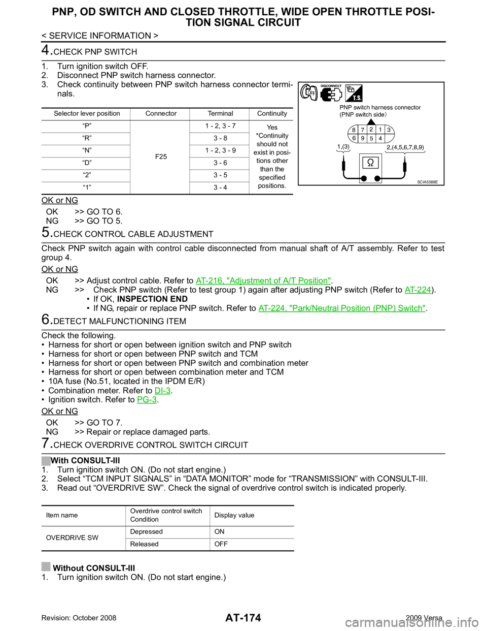
CHECK PNP SWITCH
1. Turn ignition switch OFF.
2. Disconnect PNP switch harness connector.
3. Check continuity between PNP switch harness connector termi- nals.
OK or NG OK >> GO TO 6.
NG >> GO TO 5. 5.
CHECK CONTROL CABLE ADJUSTMENT
Check PNP switch again with control cable disconnected from manual shaft of A/T assembly. Refer to test
group 4.
OK or NG OK >> Adjust control cable. Refer to
AT-216, " Adjustment of A/T Position " .
NG >> Check PNP switch (Refer to test group 1) again after adjusting PNP switch (Refer to AT-224 ).
• If OK, INSPECTION END
• If NG, repair or replace PNP switch. Refer to AT-224, " Park/Neutral Position (PNP) Switch " .
6.
DETECT MALFUNCTIONING ITEM
Check the following.
• Harness for short or open between ignition switch and PNP switch
• Harness for short or open between PNP switch and TCM
• Harness for short or open between PNP switch and combination meter
• Harness for short or open between combination meter and TCM
• 10A fuse (No.51, located in the IPDM E/R)
• Combination meter. Refer to DI-3 .
• Ignition switch. Refer to PG-3 .
OK or NG OK >> GO TO 7.
NG >> Repair or replace damaged parts. 7.
CHECK OVERDRIVE CONTROL SWITCH CIRCUIT
With CONSULT-III
1. Turn ignition switch ON. (Do not start engine.)
2. Select “TCM INPUT SIGNALS” in “DATA MONITO R” mode for “TRANSMISSION” with CONSULT-III.
3. Read out “OVERDRIVE SW”. Check the signal of ov erdrive control switch is indicated properly.
Without CONSULT-III
1. Turn ignition switch ON. (Do not start engine.) Selector lever position Connector Terminal Continuity
“P”
F251 - 2, 3 - 7
Yes
*Continuity
should not
exist in posi-
tions other than the
specified
positions.
“R” 3 - 8
“N” 1 - 2, 3 - 9
“D” 3 - 6 “2” 3 - 5
“1” 3 - 4 SCIA5588E
Item name
Overdrive control switch
Condition Display value
OVERDRIVE SW Depressed ON
Released OFF
Page 180 of 4331
AT
N
O P
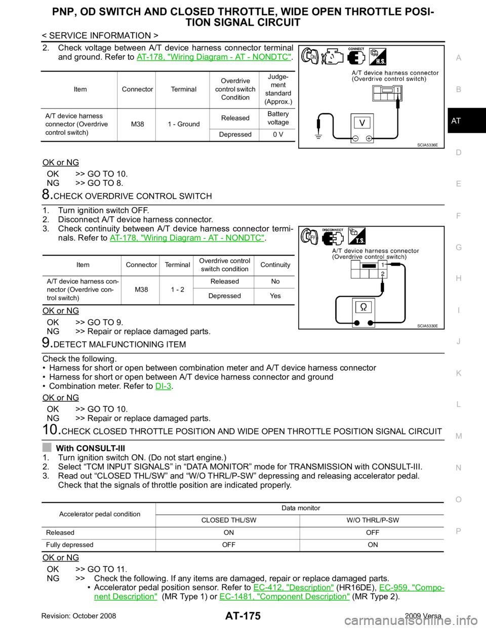
2. Check voltage between A/T device harness connector terminal
and ground. Refer to AT-178, " Wiring Diagram - AT - NONDTC " .
OK or NG OK >> GO TO 10.
NG >> GO TO 8. Wiring Diagram - AT - NONDTC " .
OK or NG OK >> GO TO 9.
NG >> Repair or replace damaged parts. .
OK or NG OK >> GO TO 10.
NG >> Repair or replace damaged parts. OK >> GO TO 11.
NG >> Check the following. If any items are damaged, repair or replace damaged parts. • Accelerator pedal position sensor. Refer to EC-412, " Description " (HR16DE),
EC-959, " Compo-
nent Description " (MR Type 1) or
EC-1481, " Component Description " (MR Type 2).
Item Connector Terminal
Overdrive
control switch Condition Judge-
ment
standard
(Approx.)
A/T device harness
connector (Overdrive
control switch) M38 1 - Ground
Released
Battery
voltage
Depressed 0 V
Page 181 of 4331
AT-176< SERVICE INFORMATION >
PNP, OD SWITCH AND CLOSED THRO
TTLE, WIDE OPEN THROTTLE POSI-
TION SIGNAL CIRCUIT 11.
PERFORM SELF-DIAGNOSIS
Without CONSULT-III
Perform self-diagnosis. Refer to AT-83, " Diagnosis Procedure without CONSULT-III " .
OK or NG OK >>
INSPECTION END
NG − 1 >> Self-diagnosis does not activate: GO TO 12.
NG − 2 >> DTC is displayed: Check the malfunctioning system. Refer to AT-83, " Diagnosis Procedure with-
out CONSULT-III " .
12.
CHECK TCM
1. Check TCM input/output signal. Refer to AT-77, " TCM Terminal and Reference Value " .
2. If NG, recheck TCM pin terminals for damage or loose connection with harness connector.
OK or NG OK >>
INSPECTION END
NG >> Repair or replace damaged parts.
Component Inspection INFOID:0000000004305467
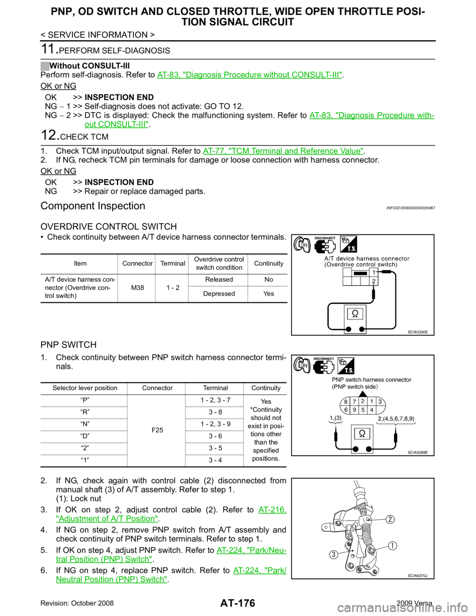
OVERDRIVE CONTROL SWITCH
• Check continuity between A/T device harness connector terminals.
PNP SWITCH
1. Check continuity between PNP switch harness connector termi- nals.
2. If NG, check again with control cable (2) disconnected from manual shaft (3) of A/T assembly. Refer to step 1.
(1): Lock nut
3. If OK on step 2, adjust control cable (2). Refer to AT-216," Adjustment of A/T Position " .
4. If NG on step 2, remove PNP switch from A/T assembly and check continuity of PNP switch terminals. Refer to step 1.
5. If OK on step 4, adjust PNP switch. Refer to AT-224, " Park/Neu-
tral Position (PNP) Switch " .
6. If NG on step 4, replace PNP switch. Refer to AT-224, " Park/
Neutral Position (PNP) Switch " .Item Connector Terminal
Overdrive control
switch condition Continuity
A/T device harness con-
nector (Overdrive con-
trol switch) M38 1 - 2Released No
Depressed Yes SCIA5330E
Selector lever position Connector Terminal Continuity
“P”
F251 - 2, 3 - 7
Yes
*Continuity
should not
exist in posi- tions other
than the
specified
positions.
“R” 3 - 8
“N” 1 - 2, 3 - 9
“D” 3 - 6 “2” 3 - 5
“1” 3 - 4 SCIA5588E
SCIA6370J
Page 189 of 4331
).
- If OK, INSPECTION END
- If NG, repair or replace PNP switch. Refer to AT-224, " Park/Neutral Position (PNP) Switch " .
.
OK or NG OK >>
INSPECTION END
NG >> Repair or replace damaged parts.
In "P" Position, Vehicle Moves Forward or Backward When Pushed INFOID:0000000004305474
SYMPTOM:
Vehicle moves when it is pushed forward or backward with selector lever in “P” position.
DIAGNOSTIC PROCEDURE Checking of A/T Position " .
OK or NG OK >> GO TO 2.
NG >> Adjust A/T position. Refer to AT-216, " Adjustment of A/T Position " .
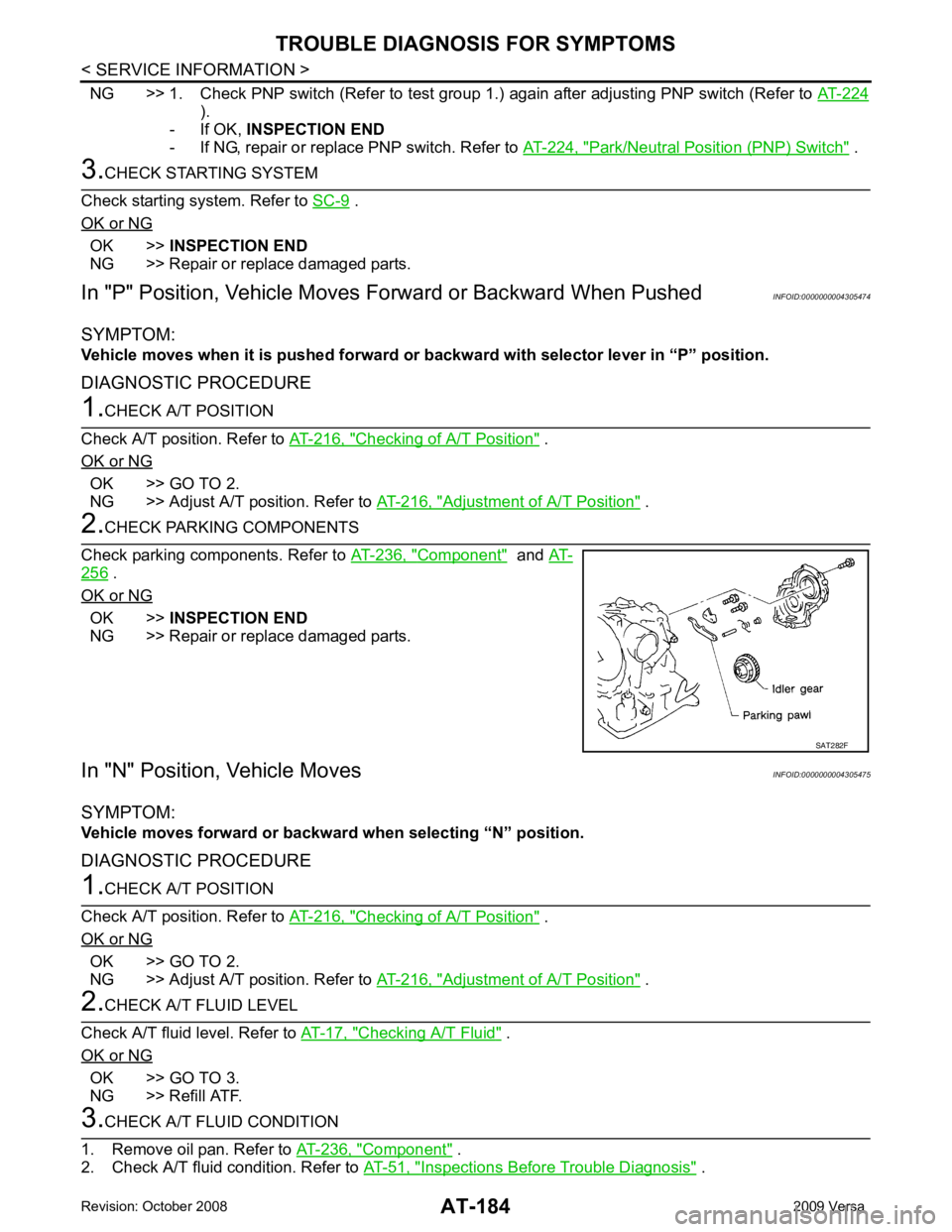
Component " and
AT- 256 .
OK or NG OK >>
INSPECTION END
NG >> Repair or replace damaged parts.
In "N" Position, Vehicle Moves INFOID:0000000004305475
SYMPTOM:
Vehicle moves forward or backwar d when selecting “N” position.
DIAGNOSTIC PROCEDURE Checking of A/T Position " .
OK or NG OK >> GO TO 2.
NG >> Adjust A/T position. Refer to AT-216, " Adjustment of A/T Position " .
Checking A/T Fluid " .
OK or NG OK >> GO TO 3.
NG >> Refill ATF. Component " .
2. Check A/T fluid condition. Refer to AT-51, " Inspections Before Trouble Diagnosis " .
Page 192 of 4331

AT
N
O P
2. Check the following items:
- Low & reverse brake assembly. Refer to AT-313, " Low & Reverse Brake " .
- Reverse clutch assembly. Refer to AT-296, " Reverse Clutch " .
OK or NG OK >> GO TO 6.
NG >> Repair or replace damaged parts. Component " .
2. Check A/T fluid condition. Refer to AT-51, " Inspections Before Trouble Diagnosis " .
OK or NG OK >> GO TO 8.
NG >> GO TO 7. Disassembly " .
2. Check the following items:
- Reverse clutch assembly. Refer to AT-296, " Reverse Clutch " .
- High clutch assembly. Refer to AT-301, " High Clutch " .
- Low & reverse brake assembly. Refer to AT-313, " Low & Reverse Brake " .
- Forward clutch assembly. Refer to AT-306, " Forward and Overrun Clutches " .
- Overrun clutch assembly. Refer to AT-306, " Forward and Overrun Clutches " .
OK or NG OK >> GO TO 8.
NG >> Repair or replace damaged parts. Check at Idle " .
OK or NG OK >>
INSPECTION END
NG >> GO TO 9. TCM Terminal and Reference Value " .
2. If NG, recheck TCM pin terminals for dam age or loose connection with harness connector.
OK or NG OK >>
INSPECTION END
NG >> Repair or replace damaged parts.
Vehicle Does Not Creep Forward in "D", "2" or "1" Position INFOID:0000000004305478
SYMPTOM: Vehicle does not creep forward when selecting “D”, “2” or “1” position.
DIAGNOSTIC PROCEDURE Checking A/T Fluid " .
OK or NG OK >> GO TO 2.
NG >> Refill ATF. Inspections Before Trouble
Diagnosis " .
OK or NG OK >> GO TO 4.
NG >> GO TO 3.
Page 193 of 4331
Control Valve Assembly and Accumulators " .
2. Check the following items:
- Valves to control line pressure (Pressure regulator valve, pressure modifier valve, pilot valve and pilot fil- ter)
- Line pressure solenoid valve
3. Disassemble A/T. Refer to AT-256, " Disassembly " .
4. Check the following item:
- Oil pump assembly. Refer to AT-277, " Oil Pump " .
OK or NG OK >> GO TO 4.
NG >> Repair or replace damaged parts. Inspections Before Trouble Diagno-
sis " .
OK or NG OK >> GO TO 6.
NG >> GO TO 5. Disassembly " .
2. Check the following items:
- Oil pump assembly. Refer to AT-277, " Oil Pump " .
- Forward clutch assembly. Refer to AT-306, " Forward and Overrun Clutches " .
- Forward one-way clutch. Refer to AT-317, " Rear Internal Gear and Forward Clutch Hub " .
- Low one-way clutch. Refer to AT-256, " Disassembly " .
- Torque converter. Refer to AT-256, " Disassembly " .
OK or NG OK >> GO TO 7.
NG >> Repair or replace damaged parts. Component " .
2. Check A/T fluid condition. Refer to AT-51, " Inspections Before Trouble Diagnosis " .
OK or NG OK >> GO TO 7.
NG >> GO TO 5. Check at Idle " .
OK or NG OK >>
INSPECTION END
NG >> GO TO 8. TCM Terminal and Reference Value " .
2. If NG, recheck TCM pin terminals for damage or loose connection with harness connector.
OK or NG OK >>
INSPECTION END
NG >> Repair or replace damaged parts.
Vehicle Cannot Be Started from D 1 INFOID:0000000004305479
SYMPTOM:
Vehicle cannot be started from D 1 on “Cruise Test — Part 1”.
Page 194 of 4331
AT
N
O P
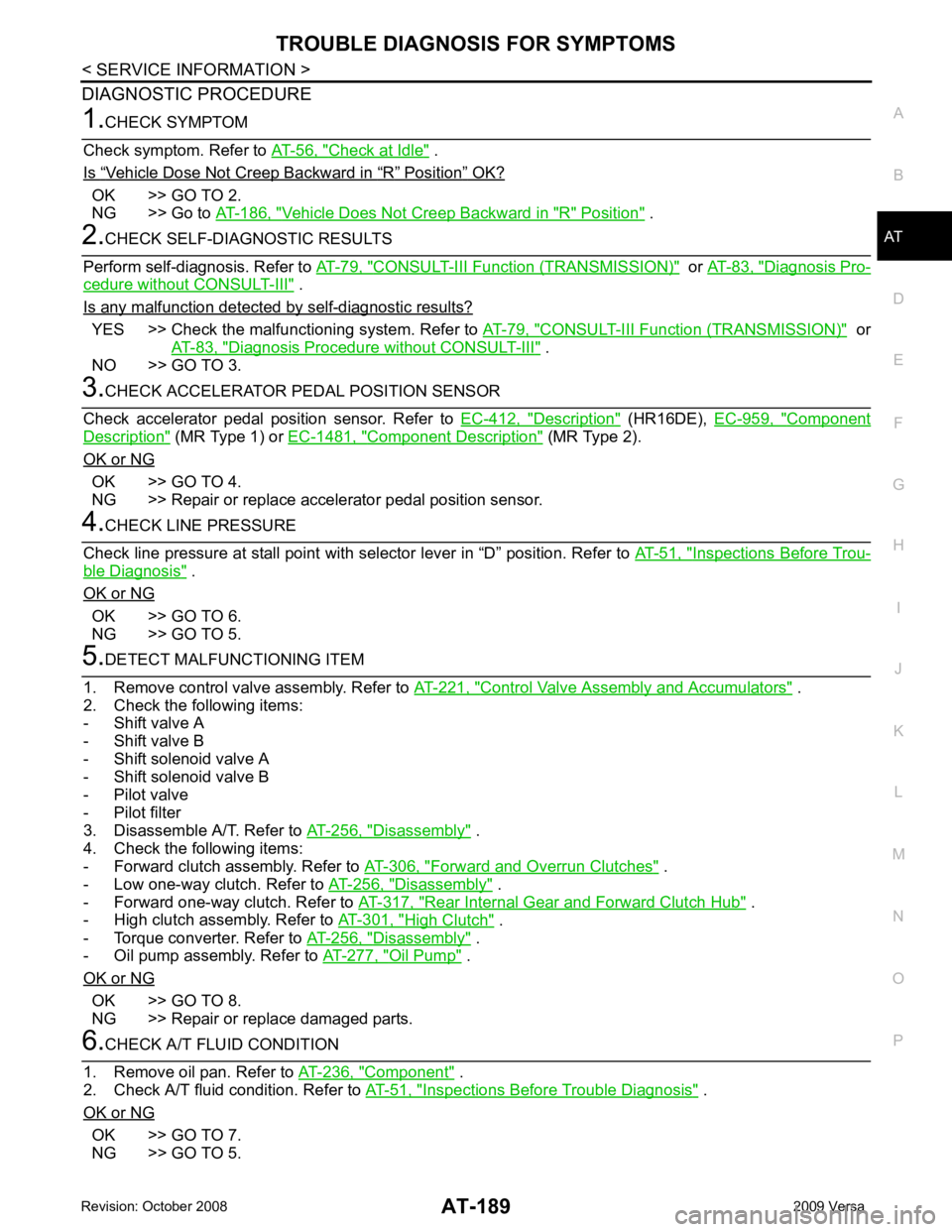
DIAGNOSTIC PROCEDURE Check at Idle " .
Is “ Vehicle Dose Not Creep Backward in “ R ” Position ” OK?
OK >> GO TO 2.
NG >> Go to AT-186, " Vehicle Does Not Creep Backward in "R" Position " .
CONSULT-III Functi
on (TRANSMISSION) " or
AT-83, " Diagnosis Pro-
cedure without CONSULT-III " .
Is any malfunction detected by self-diagnostic results? YES >> Check the malfuncti
oning system. Refer to AT-79, " CONSULT-III Functi
on (TRANSMISSION) " or
AT-83, " Diagnosis Procedure without CONSULT-III " .
NO >> GO TO 3. Description " (HR16DE),
EC-959, " Component
Description " (MR Type 1) or
EC-1481, " Component Description " (MR Type 2).
OK or NG OK >> GO TO 4.
NG >> Repair or replace accelerator pedal position sensor. Inspections Before Trou-
ble Diagnosis " .
OK or NG OK >> GO TO 6.
NG >> GO TO 5. Control Valve Assembly and Accumulators " .
2. Check the following items:
- Shift valve A
- Shift valve B
- Shift solenoid valve A
- Shift solenoid valve B
- Pilot valve
- Pilot filter
3. Disassemble A/T. Refer to AT-256, " Disassembly " .
4. Check the following items:
- Forward clutch assembly. Refer to AT-306, " Forward and Overrun Clutches " .
- Low one-way clutch. Refer to AT-256, " Disassembly " .
- Forward one-way clutch. Refer to AT-317, " Rear Internal Gear and Forward Clutch Hub " .
- High clutch assembly. Refer to AT-301, " High Clutch " .
- Torque converter. Refer to AT-256, " Disassembly " .
- Oil pump assembly. Refer to AT-277, " Oil Pump " .
OK or NG OK >> GO TO 8.
NG >> Repair or replace damaged parts. Component " .
2. Check A/T fluid condition. Refer to AT-51, " Inspections Before Trouble Diagnosis " .
OK or NG OK >> GO TO 7.
NG >> GO TO 5.