air condition NISSAN TIIDA 2009 Service Repair Manual
[x] Cancel search | Manufacturer: NISSAN, Model Year: 2009, Model line: TIIDA, Model: NISSAN TIIDA 2009Pages: 4331, PDF Size: 58.04 MB
Page 4243 of 4331
![NISSAN TIIDA 2009 Service Repair Manual PRECAUTIONS
STC-3
< SERVICE INFORMATION >
[EPS] C
D E
F
H I
J
K L
M A
B STC
N
O
P
5. When the repair work is completed, return the ignition switch to the
″LOCK ″ position before con](/img/5/57398/w960_57398-4242.png "NISSAN TIIDA 2009 Service Repair Manual PRECAUTIONS
STC-3
< SERVICE INFORMATION >
[EPS] C
D E
F
H I
J
K L
M A
B STC
N
O
P
5. When the repair work is completed, return the ignition switch to the
″LOCK ″ position before con")
PRECAUTIONS
STC-3
< SERVICE INFORMATION >
[EPS] C
D E
F
H I
J
K L
M A
B STC
N
O
P
5. When the repair work is completed, return the ignition switch to the
″LOCK ″ position before connecting
the battery cables. (At this time, the steering lock mechanism will engage.)
6. Perform a self-diagnosis check of al l control units using CONSULT-III.
Service Notice or Precaution for EPS System INFOID:0000000004307286
CAUTION:
Check or confirm the following item wh en performing the trouble diagnosis.
• Check any possible causes by interviewing the symptom and it’s condition from the customer if any
malfunction, such as EPS warn ing lamp turns ON, occurs.
• Check if air pressure and size of tires are proper, the specified part is used for the steering wheel,
and control unit is genuine part.
• Check if the connection of steer ing column assembly and steering gear assembly is proper (there is
not looseness of mounting bolts, damage of rods, boots or sealants, and leakage of grease, etc).
• Check if the wheel alignmen t is adjusted properly.
• Check if there is any damage or modification to su spension or body resulting in increased weight or
altered ground clearance.
• Check if installation conditions of each link and suspension are proper.
• Check if the battery voltage is proper
• Check connection conditions of each connector are proper.
• Before connecting or disconnect ing the EPS control unit har-
ness connector, turn ignition switch “OFF” and disconnect
battery ground cable. Because battery voltage is applied to
EPS control unit even if igniti on switch is turned “OFF”.
• When connecting or disconnect ing pin connectors into or
from EPS control unit, take care not to damage pin terminals
(bend or break).
When connecting pin connectors, make sure that there are no
bends or breaks on EPS control unit pin terminal.
• Before replacing EPS control unit, perform EPS control unit input/output signal inspectio n and make sure whether EPS
control unit functions properly or not. Refer to STC-9, " EPS
Control Unit Input/Output Signal Reference Value " . SEF289H
SEF291H
SDIA1848E
Page 4246 of 4331
![NISSAN TIIDA 2009 Service Repair Manual STC-6< SERVICE INFORMATION >
[EPS]
TROUBLE DIAGNOSIS
TROUBLE DIAGNOSIS
Fail-Safe Function INFOID:0000000004307290
• If any malfunction occurs in the system, and control unit detects the malfunction](/img/5/57398/w960_57398-4245.png "NISSAN TIIDA 2009 Service Repair Manual STC-6< SERVICE INFORMATION >
[EPS]
TROUBLE DIAGNOSIS
TROUBLE DIAGNOSIS
Fail-Safe Function INFOID:0000000004307290
• If any malfunction occurs in the system, and control unit detects the malfunction")
STC-6< SERVICE INFORMATION >
[EPS]
TROUBLE DIAGNOSIS
TROUBLE DIAGNOSIS
Fail-Safe Function INFOID:0000000004307290
• If any malfunction occurs in the system, and control unit detects the malfunction, EPS warning lamp on com-
bination meter turns ON to indicate system malfunction.
• When EPS warning lamp is ON, enters a manual steer ing state. (Control turning force steering wheel
becomes heavy.)
How to Perform Trouble Diagnosis INFOID:0000000004307291
BASIC CONCEPT
• To perform trouble diagnosis, it is a must to have an understanding about vehicle systems (control and mechanism) thoroughly.
• It is also important to clarify customer complaints before starting
the inspection.
First of all, reproduce the symptoms, and understand them fully.
Ask customer about his/her complaints carefully. In some cases, it
will be necessary to check symptoms by driving vehicle with cus-
tomer.
CAUTION:
Customers are not professionals. It is dangerous to make an
easy guess like “maybe the customer means that...” or
“maybe the customer mentions this symptom”.
• It is essential to check symptoms right from the beginning in order to repair malfunctions completely.
For intermittent malfunctions, reproduce symptoms based on inter-
view with customer and past examples. Do not perform inspection
on ad hoc basis. Most intermittent malfunctions are caused by
poor contacts. In this case, it will be effective to shake suspected
harness or connector by hand. When repairing without any symp-
tom diagnosis, you cannot judge if malfunctions has actually been
eliminated.
PRECAUTIONS FOR TROUBLE DIAGNOSIS
• Be sure to check the procedures of the trouble diagnosis in advance. Refer to "How to Perform Trouble Diagnosis" .
• Always erase memory after completing trouble diagnosis. Refer to STC-11, " CONSULT-III Function (EPS) " .
• Checking continuity and voltage between units, be sure to check connector terminals for disconnection,
looseness, bend, or collapse. Repair or replace app licable part if any non-standard condition is detected.
• Be careful not to forcibly extend any connector terminal if a circuit tester is used for the check.
• Always confirm the general precautions. Refer to GI-3, " General Precaution " .
INTERVIEW
• Complaints vary depending on the person. It is important to clarify the customer's actual remarks.
• Ask the customer about what sy mptoms occur under what condi-
tions. Use the information to reproduce the symptom of confirm by
vehicle. SEF233G
SEF234G
SEF907L
Page 4259 of 4331
STC
N
O P
OK >>
INSPECTION END
NG >> Perform self-diagnosis with ABS actuator and el ectric unit (control unit) and combination meter.
Refer to BRC-18, " CONSULT-III Function (ABS) " ,
DI-12, " CONSULT-III Function (METER/M&A) "
.
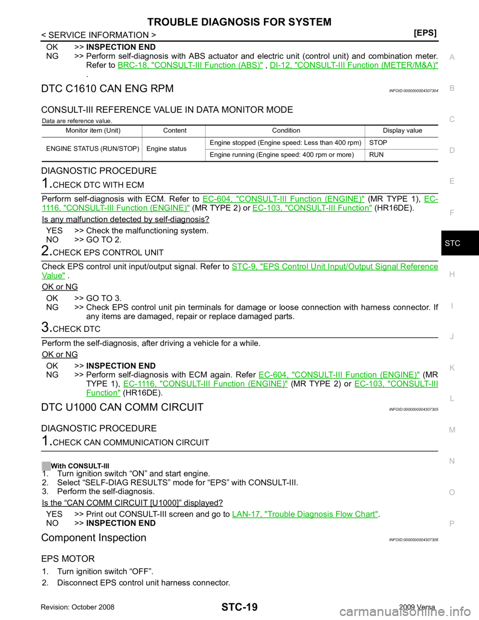
DTC C1610 CAN ENG RPM INFOID:0000000004307304
CONSULT-III REFERENCE VALUE IN DATA MONITOR MODE Data are reference value.
DIAGNOSTIC PROCEDURE CONSULT-III Function (ENGINE) " (MR TYPE 1),
EC-1116, " CONSULT-III F
unction (ENGINE) " (MR TYPE 2) or
EC-103, " CONSULT-III Function " (HR16DE).
Is any malfunction detected by self-diagnosis? YES >> Check the malfunctioning system.
NO >> GO TO 2. EPS Control Unit Input/Output Signal Reference
Value " .
OK or NG OK >> GO TO 3.
NG >> Check EPS control unit pin terminals for damage or loose connection with harness connector. If
any items are damaged, repair or replace damaged parts. OK >>
INSPECTION END
NG >> Perform self-diagnosis with ECM again. Refer EC-604, " CONSULT-III Function (ENGINE) " (MR
TYPE 1), EC-1116, " CONSULT-III Function (ENGINE) " (MR TYPE 2) or
EC-103, " CONSULT-III
Function " (HR16DE).
DTC U1000 CAN COMM CIRCUIT INFOID:0000000004307305
DIAGNOSTIC PROCEDURE “ CAN COMM CIRCUIT [U1000] ” displayed?
YES >> Print out CONSULT-III screen and go to
LAN-17, " Trouble Diagnosis Flow Chart " .
NO >> INSPECTION END
Component Inspection INFOID:0000000004307306
EPS MOTOR 1. Turn ignition switch “OFF”.
2. Disconnect EPS control unit harness connector. Monitor item (Unit) Content Condition Display value
ENGINE STATUS (RUN/STOP) Engine status Engine stopped (Engine speed: Less than 400 rpm) STOP
Engine running (Engine speed: 400 rpm or more) RUN
Page 4274 of 4331
WT
N
O P
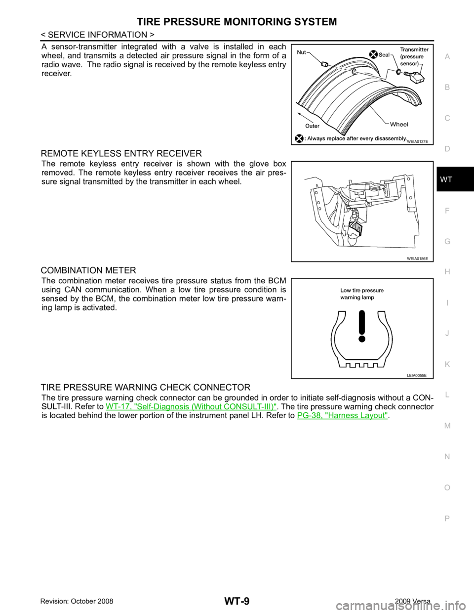
A sensor-transmitter integrated with a valve is installed in each
wheel, and transmits a detected air pressure signal in the form of a
radio wave. The radio signal is received by the remote keyless entry
receiver.
REMOTE KEYLESS ENTRY RECEIVER The remote keyless entry receiver is shown with the glove box
removed. The remote keyless entry receiver receives the air pres-
sure signal transmitted by the transmitter in each wheel.
COMBINATION METER The combination meter receives tire pressure status from the BCM
using CAN communication. When a low tire pressure condition is
sensed by the BCM, the combination meter low tire pressure warn-
ing lamp is activated.
TIRE PRESSURE WARNING CHECK CONNECTOR The tire pressure warning check connector can be grounded in order to initiate self-diagnosis without a CON-
SULT-III. Refer to WT-17, " Self-Diagnosis (Without CONSULT-III) " . The tire pressure warning check connector
is located behind the lower portion of the instrument panel LH. Refer to PG-38, " Harness Layout " . WEIA0186E
LEIA0055E
Page 4282 of 4331
WT
N
O P
NOTE:
Before performing the self-diagnosis, be sure to register the ID or else the actual malfunction location may be different from that dis-
played on CONSULT-III.
Data Monitor Mode
NOTE:
Before performing the self-diagnosis, be sure to register the ID, or the actual malfunction location may be different from that displayed on
CONSULT-III.
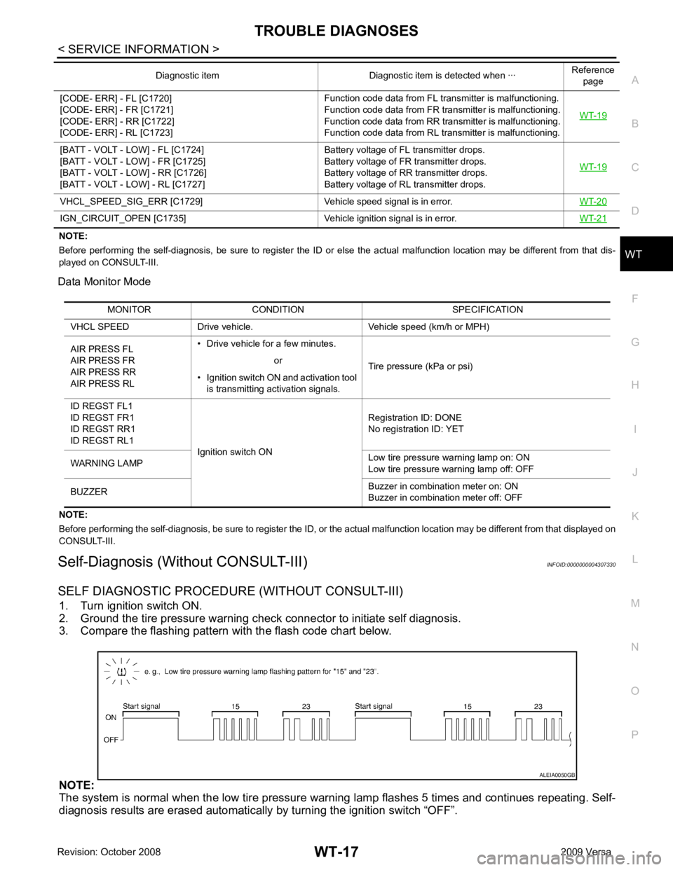
Self-Diagnosis (Without CONSULT-III) INFOID:0000000004307330
SELF DIAGNOSTIC PROCE DURE (WITHOUT CONSULT-III)
1. Turn ignition switch ON.
2. Ground the tire pressure warning check connector to initiate self diagnosis.
3. Compare the flashing pattern with the flash code chart below.
NOTE:
The system is normal when the low tire pressure warni ng lamp flashes 5 times and continues repeating. Self-
diagnosis results are erased automatically by turning the ignition switch “OFF”.
[CODE- ERR] - FL [C1720]
[CODE- ERR] - FR [C1721]
[CODE- ERR] - RR [C1722]
[CODE- ERR] - RL [C1723] Function code data from FL transmitter is malfunctioning.
Function code data from FR transmitter is malfunctioning.
Function code data from RR transmitter is malfunctioning.
Function code data from RL transmitter is malfunctioning. WT-19[BATT - VOLT - LOW] - FL [C1724]
[BATT - VOLT - LOW] - FR [C1725]
[BATT - VOLT - LOW] - RR [C1726]
[BATT - VOLT - LOW] - RL [C1727] Battery voltage of FL transmitter drops.
Battery voltage of FR transmitter drops.
Battery voltage of RR transmitter drops.
Battery voltage of RL transmitter drops. WT-19VHCL_SPEED_SIG_ERR [C1729] Vehicle
speed signal is in error.WT-20IGN_CIRCUIT_OPEN [C1735] Vehicle
ignition signal is in error. WT-21Diagnostic item Diagnostic item is detected when ···
Reference
page MONITOR CONDITION SPECIFICATION
VHCL SPEED Drive vehicle. Vehicle speed (km/h or MPH)
AIR PRESS FL
AIR PRESS FR
AIR PRESS RR
AIR PRESS RL • Drive vehicle for a few minutes.
Tire pressure (kPa or psi)
or
• Ignition switch ON and activation tool is transmitting activation signals.
ID REGST FL1
ID REGST FR1
ID REGST RR1
ID REGST RL1 Ignition switch ON Registration ID: DONE
No registration ID: YET
WARNING LAMP Low tire pressure
warning lamp on: ON
Low tire pressure warning lamp off: OFF
BUZZER Buzzer in combination meter on: ON
Buzzer in combination meter off: OFF