wheel bolts NISSAN TIIDA 2009 Service Owner's Manual
[x] Cancel search | Manufacturer: NISSAN, Model Year: 2009, Model line: TIIDA, Model: NISSAN TIIDA 2009Pages: 4331, PDF Size: 58.04 MB
Page 3791 of 4331
MA-48< SERVICE INFORMATION >
CHASSIS AND BODY MAINTENANCE
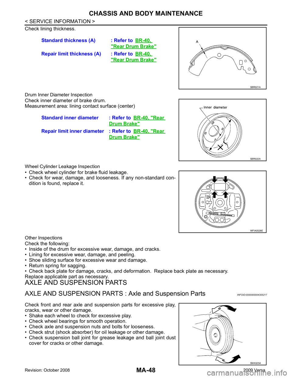
Check lining thickness.
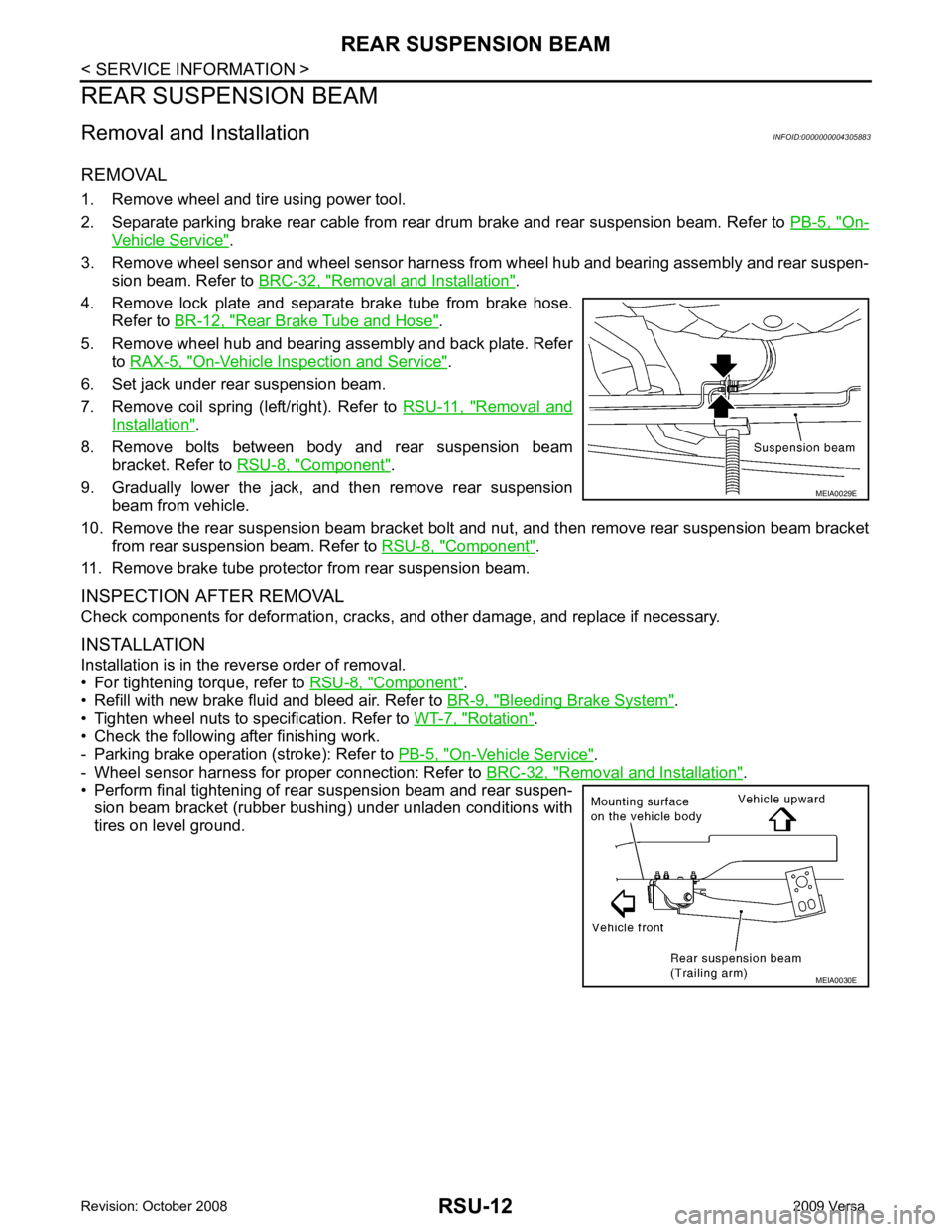
Drum Inner Diameter Inspection
Check inner diameter of brake drum.
Measurement area: lining contact surface (center)
Wheel Cylinder Leakage Inspection
• Check wheel cylinder for brake fluid leakage.
• Check for wear, damage, and looseness. If any non-standard con-
dition is found, replace it.
Other Inspections
Check the following:
• Inside of the drum for excessive wear, damage, and cracks.
• Lining for excessive wear, damage, and peeling.
• Shoe sliding surface for excessive wear and damage.
• Return spring for sagging.
• Check back plate for damage, cracks, and deforma tion. Replace back plate as necessary.
Replace applicable part as necessary.
AXLE AND SUSPENSION PARTS
AXLE AND SUSPENSION PARTS : Axle and Suspension Parts INFOID:0000000004305217
Check front and rear axle and suspension parts for excessive play,
cracks, wear or other damage.
• Shake each wheel to check for excessive play.
• Check wheel bearings for smooth operation.
• Check axle and suspension nuts and bolts for looseness.
• Check strut (shock absorber) for oil leakage or other damage.
• Check suspension ball joint for grease leakage and ball joint dust cover for cracks or other damage. Standard thickness (A) : Refer to
BR-40, " Rear Drum Brake "
Repair limit thickness (A) : Refer to
BR-40, " Rear Drum Brake "
SBR021A
Standard inner diameter : Refer to
BR-40, " Rear
Drum Brake "
Repair limit inner diameter : Refer to
BR-40, " Rear
Drum Brake "
SBR022A
WFIA0528E
SMA525A
Page 4060 of 4331
PS-4< SERVICE INFORMATION >
PREPARATION
PREPARATION
Special Service Tool INFOID:0000000004305928
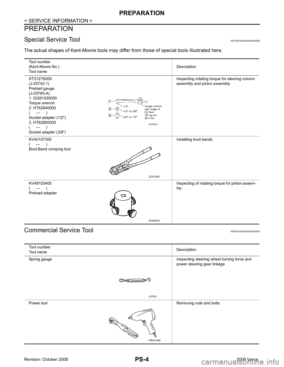
The actual shapes of K ent-Moore tools may differ from thos e of special tools illustrated here.
Commercial Service Tool INFOID:0000000004305929
Tool number
(Kent-Moore No.)
Tool name Description
ST3127S000
(J-25742-1)
Preload gauge
(J-25765-A)
1. GG91030000
Torque wrench
2. HT62940000
( — )
Socket adapter (1/2")
3. HT62900000
( — )
Socket adapter (3/8") Inspecting rotating torque for steering column
assembly and pinion assembly
KV40107300
( — )
Boot Band crimping tool Installing boot bands
KV48103400
( — )
Preload adapter Inspecting of rotating torque for pinion assem-
bly S-NT541
ZZA1229D
ZZA0824D
Tool number
Tool name Description
Spring gauge Inspecting steering wheel turning force and
power steering gear linkage
Power tool Removing nuts and bolts LST025
PBIC0190E
Page 4068 of 4331
Rotation " .
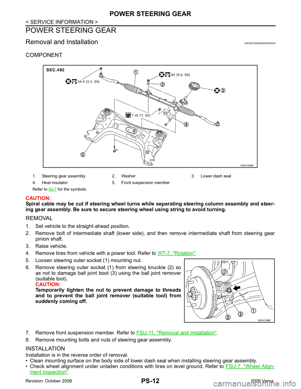
5. Loosen steering outer socket (1) mounting nut.
6. Remove steering outer socket (1) from steering knuckle (2) so as not to damage ball joint boot (3) using the ball joint remover
(suitable tool).
CAUTION:
Temporarily tighten the nut to prevent damage to threads
and to prevent the ball joint remover (suitable tool) from
suddenly coming off.
7. Remove front suspension member. Refer to FSU-11, " Removal and Installation " .
8. Remove mounting bolts and nuts of steering gear assembly.
INSTALLATION
Installation is in the reverse order of removal.
• Clean mounting surface on the body side of lower dash seal when installing steering gear assembly.
• Check wheel alignment under unladen conditions with tires on level ground. Refer to FSU-7, " Wheel Align-
ment Inspection " .
1. Steering gear assembly 2. Washer 3. Lower dash seal
4. Heat insulator 5. Front suspension member
Refer to GI-7 for the symbols.
SGIA1298E
Page 4080 of 4331

Removal and Installation of Drum Brake Assembly " .
4. Remove wheel hub and bearing assembly bolts, and then remove wheel hub and bearing assembly from vehicle.
5. If necessary remove back plate, following procedure. 1. Remove parking brake rear cable from back plate. Refer to PB-6, " Removal and Installation " .
2. Separate brake tube from wheel cylinder. Refer to BR-12, " Rear Brake Tube and Hose " .
INSPECTION AFTER REMOVAL
Check for any deformity, cracks, or other damage on the wheel hub assembly, replace if necessary.
CAUTION:
The wheel hub assembly does not require maintenance. If any of the following symptoms are noted,
replace the wheel hub assembly.
• Growling noise is emitted from the wheel hub bearing during operation.
• Wheel hub bearing drags or turns roughly.
INSTALLATION
Installation is in the reverse order of removal.
Page 4123 of 4331
On-
Vehicle Service " .
3. Remove wheel sensor and wheel sensor harness from wheel hub and bearing assembly and rear suspen-
sion beam. Refer to BRC-32, " Removal and Installation " .
4. Remove lock plate and separate brake tube from brake hose. Refer to BR-12, " Rear Brake Tube and Hose " .
5. Remove wheel hub and bearing assembly and back plate. Refer to RAX-5, " On-Vehicle Inspection and Service " .
6. Set jack under rear suspension beam.
7. Remove coil spring (left/right). Refer to RSU-11, " Removal and
Installation " .
8. Remove bolts between body and rear suspension beam bracket. Refer to RSU-8, " Component " .
9. Gradually lower the jack, and then remove rear suspension beam from vehicle.
10. Remove the rear suspension beam bracket bolt and nut, and then remove rear suspension beam bracket
from rear suspension beam. Refer to RSU-8, " Component " .
11. Remove brake tube protector from rear suspension beam.
INSPECTION AFTER REMOVAL
Check components for deformation, cracks, and other damage, and replace if necessary.
INSTALLATION
Installation is in the reverse order of removal.
• For tightening torque, refer to RSU-8, " Component " .
• Refill with new brake fluid and bleed air. Refer to BR-9, " Bleeding Brake System " .
• Tighten wheel nuts to specification. Refer to WT-7, " Rotation " .
• Check the following after finishing work.
- Parking brake operation (stroke): Refer to PB-5, " On-Vehicle Service " .
- Wheel sensor harness for proper connection: Refer to BRC-32, " Removal and Installation " .
• Perform final tightening of rear suspension beam and rear suspen-
sion beam bracket (rubber bushing) under unladen conditions with
tires on level ground. MEIA0030E
Page 4243 of 4331
![NISSAN TIIDA 2009 Service Owners Manual PRECAUTIONS
STC-3
< SERVICE INFORMATION >
[EPS] C
D E
F
H I
J
K L
M A
B STC
N
O
P
5. When the repair work is completed, return the ignition switch to the
″LOCK ″ position before con](/img/5/57398/w960_57398-4242.png "NISSAN TIIDA 2009 Service Owners Manual PRECAUTIONS
STC-3
< SERVICE INFORMATION >
[EPS] C
D E
F
H I
J
K L
M A
B STC
N
O
P
5. When the repair work is completed, return the ignition switch to the
″LOCK ″ position before con")
PRECAUTIONS
STC-3
< SERVICE INFORMATION >
[EPS] C
D E
F
H I
J
K L
M A
B STC
N
O
P
5. When the repair work is completed, return the ignition switch to the
″LOCK ″ position before connecting
the battery cables. (At this time, the steering lock mechanism will engage.)
6. Perform a self-diagnosis check of al l control units using CONSULT-III.
Service Notice or Precaution for EPS System INFOID:0000000004307286
CAUTION:
Check or confirm the following item wh en performing the trouble diagnosis.
• Check any possible causes by interviewing the symptom and it’s condition from the customer if any
malfunction, such as EPS warn ing lamp turns ON, occurs.
• Check if air pressure and size of tires are proper, the specified part is used for the steering wheel,
and control unit is genuine part.
• Check if the connection of steer ing column assembly and steering gear assembly is proper (there is
not looseness of mounting bolts, damage of rods, boots or sealants, and leakage of grease, etc).
• Check if the wheel alignmen t is adjusted properly.
• Check if there is any damage or modification to su spension or body resulting in increased weight or
altered ground clearance.
• Check if installation conditions of each link and suspension are proper.
• Check if the battery voltage is proper
• Check connection conditions of each connector are proper.
• Before connecting or disconnect ing the EPS control unit har-
ness connector, turn ignition switch “OFF” and disconnect
battery ground cable. Because battery voltage is applied to
EPS control unit even if igniti on switch is turned “OFF”.
• When connecting or disconnect ing pin connectors into or
from EPS control unit, take care not to damage pin terminals
(bend or break).
When connecting pin connectors, make sure that there are no
bends or breaks on EPS control unit pin terminal.
• Before replacing EPS control unit, perform EPS control unit input/output signal inspectio n and make sure whether EPS
control unit functions properly or not. Refer to STC-9, " EPS
Control Unit Input/Output Signal Reference Value " . SEF289H
SEF291H
SDIA1848E