Pressure switch NISSAN TIIDA 2009 Service Owner's Guide
[x] Cancel search | Manufacturer: NISSAN, Model Year: 2009, Model line: TIIDA, Model: NISSAN TIIDA 2009Pages: 4331, PDF Size: 58.04 MB
Page 996 of 4331

Item name Condition Display value (Approx.)
VSP SENSOR During driving Approximately matches the speedometer
reading.
ESTM VSP SIG*
PRI SPEED SEN During driving (lock-up ON) Approximately matches the engine speed.
ENG SPEED SIG Engine running Closely matches the tachometer reading.
SEC HYDR SEN “N” position idle 1.0 V
PRI HYDR SEN “N” position idle 0.7 V
ATF TEMP SEN When CVT fluid temperature is 20
°C (68 °F). 2.0 V
When CVT fluid temperature is 80 °C (176 °F). 1.0 V
VIGN SEN Ignition switch: ON Battery voltage
VEHICLE SPEED During driving Approximately matches the speedometer
reading.
PRI SPEED During driving (lock-up ON) Approximately matches the engine speed.
SEC SPEED During driving 50 X Approximately matches the speedom-
eter reading.
ENG SPEED Engine running Closely ma tches the tachometer reading.
GEAR RATIO During driving 2.56 - 0.43
ACC PEDAL OPEN Released accelerator pedal - Fully depressed
accelerator pedal 0.0/8 - 8.0/8
SEC PRESS “N” position idle 0.8 MPa
PRI PRESS “N” position idle 0.4 MPa
STM STEP During driving −20 step - 180 step
ISOLT1 Lock-up OFF 0.0 A
Lock-up ON 0.7 A
ISOLT2 Release your foot from the accelerator pedal. 0.8 A
Press the accelerator pedal all the way down. 0.0 A
ISOLT3 Secondary pressure low - Secondary pressure
high. 0.8 - 0.0 A
SOLMON1 Lock-up OFF 0.0 A
Lock-up ON 0.7 A
SOLMON2 “N” position idle 0.8 A
When stalled 0.3 - 0.6 A
SOLMON3 “N” position idle 0.6 - 0.7 A
When stalled 0.4 - 0.6 A
INH SW3M Selector lever in “D
” and “L” positions ON
Selector lever in “”, “” and “” positions OFF
INH SW4 Selector lever in “R” and “” positions ON
Selector lever in “”, “” and “” positions OFF
Page 1001 of 4331

CVT
N
O P
ENG SPEED (rpm) — X
SLIP REV (rpm) — X Difference between engine speed and primary
pulley speed
GEAR RATIO — X
G SPEED (G) — —
ACC PEDAL OPEN (0.0/8) X X Degree of opening for accelerator recognized by
the TCM
For fail-safe operation, the specific value used for
control is displayed.
TRQ RTO — —
SEC PRESS (MPa) — X
PRI PRESS (MPa) — X
ATFTEMP COUNT — X Means CVT fluid temperature. Actual oil temper-
ature ( °C) cannot be checked unless a numeric
value is converted. Refer to CVT-12 .
DSR REV (rpm) — —
DGEAR RATIO — —
DSTM STEP (step) — —
STM STEP (step) — X
LU PRS (MPa) — —
LINE PRS (MPa) — —
TGT SEC PRESS (MPa) — —
ISOLT1 (A) — X Torque converter clutch solenoid valve output
current
ISOLT2 (A) — X Pressure control solenoid valve A (line pressure
solenoid valve) output current
ISOLT3 (A) — X Pressure control solenoid valve B (secondary
pressure solenoid valve) output current
SOLMON1 (A) X X Torque converter clutch solenoid valve monitor
current
SOLMON2 (A) X X Pressure control solenoid valve A (line pressure
solenoid valve) monitor current
SOLMON3 (A) X X Pressure control solenoid valve B (secondary
pressure solenoid va lve) monitor current
INH SW3M (ON/OFF) X — PNP switch 3 ON-OFF status monitor
INH SW4 (ON/OFF) X — PNP switch 4 ON-OFF status
INH SW3 (ON/OFF) X — PNP switch 3 ON-OFF status
INH SW2 (ON/OFF) X — PNP switch 2 ON-OFF status
INH SW1 (ON/OFF) X — PNP switch 1 ON-OFF status
BRAKE SW (ON/OFF) X X Stop lamp switch (Signal input with CAN comuni-
cation)
Monitored item (Unit)
Monitor item selection
Remarks
ECU IN-
PUT SIG- NALS MAIN SIG-
NALS SELEC-
TION
FROM
MENU
Page 1035 of 4331
CVT
N
O P
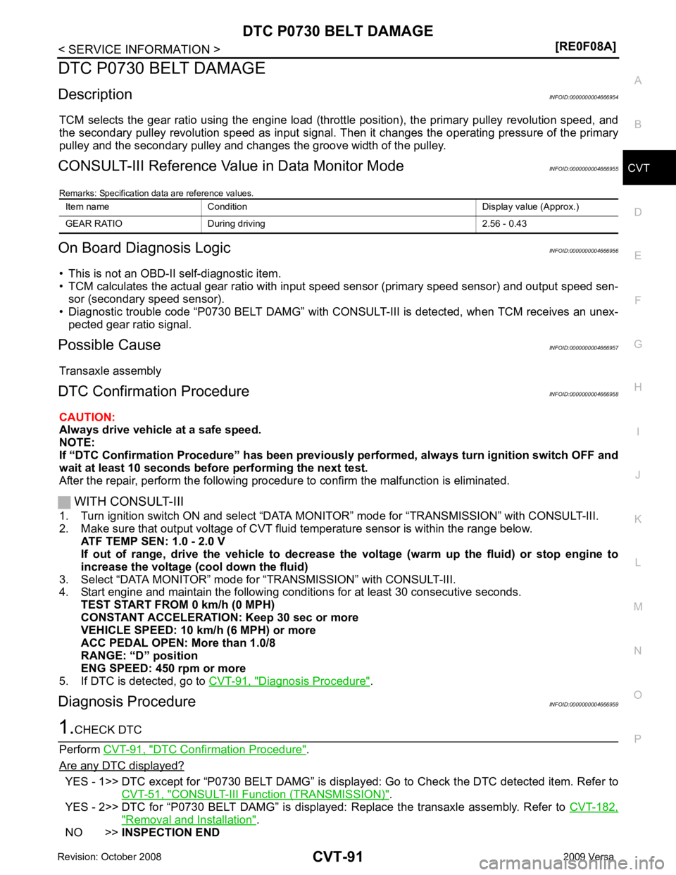
DTC P0730 BELT DAMAGE
Description INFOID:0000000004666954
TCM selects the gear ratio using the engine load (throttle position), the primary pulley revolution speed, and
the secondary pulley revolution speed as input signal. T hen it changes the operating pressure of the primary
pulley and the secondary pulley and changes the groove width of the pulley.
CONSULT-III Reference Val ue in Data Monitor Mode INFOID:0000000004666955
Remarks: Specification data are reference values.
On Board Diagnosis Logic INFOID:0000000004666956
• This is not an OBD-II self-diagnostic item.
• TCM calculates the actual gear ratio with input speed sensor (primary speed sensor) and output speed sen-
sor (secondary speed sensor).
• Diagnostic trouble code “P0730 BELT DAMG” with CONSUL T-III is detected, when TCM receives an unex-
pected gear ratio signal.
Possible Cause INFOID:0000000004666957
Transaxle assembly
DTC Confirmation Procedure INFOID:0000000004666958
CAUTION:
Always drive vehicle at a safe speed.
NOTE:
If “DTC Confirmation Procedure” has been previously performed, alw ays turn ignition switch OFF and
wait at least 10 seconds before performing the next test.
After the repair, perform the following procedure to confirm the malfunction is eliminated.
WITH CONSULT-III
1. Turn ignition switch ON and select “DATA MO NITOR” mode for “TRANSMISSION” with CONSULT-III.
2. Make sure that output voltage of CVT fluid temperature sensor is within the range below.
ATF TEMP SEN: 1.0 - 2.0 V
If out of range, drive the vehicle to decrease the voltage (warm up the fluid) or stop engine to
increase the voltage (c ool down the fluid)
3. Select “DATA MONITOR” mode for “TRANSMISSION” with CONSULT-III.
4. Start engine and maintain the following conditions for at least 30 consecutive seconds.
TEST START FROM 0 km/h (0 MPH)
CONSTANT ACCELERATION: Keep 30 sec or more
VEHICLE SPEED: 10 km/h (6 MPH) or more
ACC PEDAL OPEN: More than 1.0/8
RANGE: “D” position
ENG SPEED: 450 rpm or more
5. If DTC is detected, go to CVT-91, " Diagnosis Procedure " .
Diagnosis Procedure INFOID:0000000004666959DTC Confirmation Procedure " .
Are any DTC displayed? YES - 1>> DTC except for “P0730 BELT DAMG” is displa
yed: Go to Check the DTC detected item. Refer to
CVT-51, " CONSULT-III Function (TRANSMISSION) " .
YES - 2>> DTC for “P0730 BELT DAMG” is displayed: Replace the transaxle assembly. Refer to CVT-182," Removal and Installation " .
NO >> INSPECTION END
Item name Condition Display value (Approx.)
GEAR RATIO During driving 2.56 - 0.43
Page 1043 of 4331

CVT
N
O P
DTC P0745 LINE PRESSURE SOLENOID VALVE
Description INFOID:0000000004666974
• The pressure control solenoid valve A (line pressure solenoid valve) is included in the control valve assem- bly.
• The pressure control solenoid valve A (line pressure solenoid valve) regulates the oil pump discharge pres-
sure to suit the driving condition in response to a signal sent from the TCM.
CONSULT-III Reference Val ue in Data Monitor Mode INFOID:0000000004666975
Remarks: Specification data are reference values.
On Board Diagnosis Logic INFOID:0000000004666976
• This is an OBD-II self-diagnostic item.
• Diagnostic trouble code “P0745 L/PRESS SOL/CIRC” with CONSULT-III is detected under the following
conditions.
- TCM detects an improper voltage drop when it tries to operate the solenoid valve.
- When TCM compares target value with monitor value and detects an irregularity.
Possible Cause INFOID:0000000004666977
• Harness or connectors (Solenoid circuit is open or shorted.)
• Pressure control solenoid valve A (Line pressure solenoid valve)
DTC Confirmation Procedure INFOID:0000000004666978
NOTE:
If “DTC Confirmation Procedure” has been previously performed, alw ays turn ignition switch OFF and
wait at least 10 seconds before performing the next test.
After the repair, perform the following procedure to confirm the malfunction is eliminated.
WITH CONSULT-III
1. Turn ignition switch ON and select “DATA MO NITOR” mode for “TRANSMISSION” with CONSULT-III.
2. Start engine and wait at least 5 seconds.
3. If DTC is detected, go to CVT-101, " Diagnosis Procedure " .
WITH GST
Follow the procedure “WITH CONSULT-III”. Item name Condition Display value (Approx.)
ISOLT2 Release your foot from the accelerator pedal. 0.8 A
Press the accelerator pedal all the way down. 0.0 A
Page 1046 of 4331
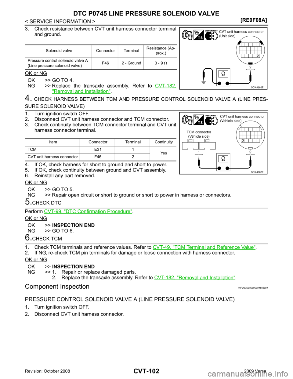
OK >> GO TO 4.
NG >> Replace the transaxle assembly. Refer to CVT-182," Removal and Installation " .
4. CHECK HARNESS BETWEEN TCM AND PRESSURE CONTROL SOLENOID VALVE A (LINE PRES-OK >> GO TO 5.
NG >> Repair open circuit or short to ground or short to power in harness or connectors. DTC Confirmation Procedure " .
OK or NG OK >>
INSPECTION END
NG >> GO TO 6. TCM Terminal and Reference Value " .
2. If NG, re-check TCM pin terminals for damage or loose connection with harness connector.
OK or NG OK >>
INSPECTION END
NG >> 1. Repair or replace damaged parts. 2. Replace the transaxle assembly. Refer to CVT-182, " Removal and Installation " .
Component Inspection INFOID:0000000004666981
PRESSURE CONTROL SOLENOID VALVE A (LINE PRESSURE SOLENOID VALVE)
1. Turn ignition switch OFF.
2. Disconnect CVT unit harness connector. Solenoid valve Connector Terminal
Resistance (Ap-
prox.)
Pressure control solenoid valve A
(Line pressure solenoid valve) F46 2 - Ground 3 - 9
Ω
Page 1055 of 4331
CVT
N
O P
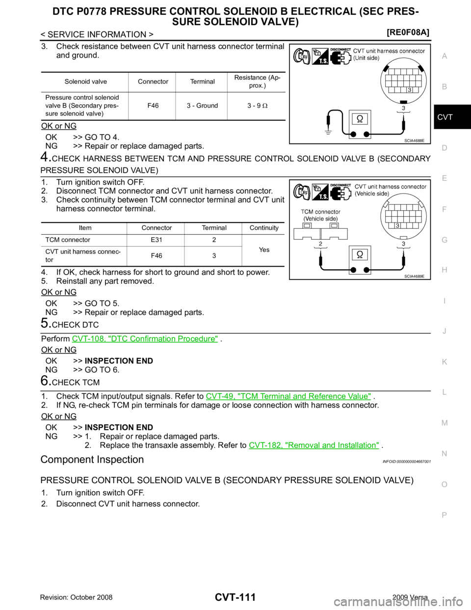
3. Check resistance between CVT unit harness connector terminal
and ground.
OK or NG OK >> GO TO 4.
NG >> Repair or replace damaged parts.
4. CHECK HARNESS BETWEEN TCM AND PRESSURE CONTROL SOLENOID VALVE B (SECONDARYOK >> GO TO 5.
NG >> Repair or replace damaged parts. DTC Confirmation Procedure " .
OK or NG OK >>
INSPECTION END
NG >> GO TO 6. TCM Terminal and Reference Value " .
2. If NG, re-check TCM pin terminals for dam age or loose connection with harness connector.
OK or NG OK >>
INSPECTION END
NG >> 1. Repair or replace damaged parts. 2. Replace the transaxle assembly. Refer to CVT-182, " Removal and Installation " .
Component Inspection INFOID:0000000004667001
PRESSURE CONTROL SOLENOID VALVE B (S ECONDARY PRESSURE SOLENOID VALVE)
1. Turn ignition switch OFF.
2. Disconnect CVT unit harness connector. Solenoid valve Connector Terminal
Resistance (Ap-
prox.)
Pressure control solenoid
valve B (Secondary pres-
sure solenoid valve) F46 3 - Ground 3 - 9
Ω
Page 1057 of 4331

CVT
N
O P
DTC P0840 TRANSMISSION FLUID
PRESSURE SENSOR A CIRCUIT
(SEC PRESSURE SENSOR)
Description INFOID:0000000004667002
• The transmission fluid pressure sensor A (secondary pressure sensor) is included in the control valve
assembly.
• The transmission fluid pressure sensor A (secondary pressure sensor) detects secondary pressure of CVT
and sends TCM the signal.
CONSULT-III Reference Val ue in Data Monitor Mode INFOID:0000000004667003
Remarks: Specification data are reference values.
On Board Diagnosis Logic INFOID:0000000004667004
• This is an OBD-II self-diagnostic item.
• Diagnostic trouble code “P0840 TR PRS SENS/A CIRC” with CONSULT-III is detected when TCM detects
an improper voltage drop when it receives the sensor signal.
Possible Cause INFOID:0000000004667005
• Transmission fluid pressure sensor A (Secondary pressure sensor)
• Harness or connectors (Switch circuit is open or shorted.)
DTC Confirmation Procedure INFOID:0000000004667006
NOTE:
If “DTC Confirmation Procedure” has been previously performed, alw ays turn ignition switch OFF and
wait at least 10 seconds before performing the next test.
After the repair, perform the following procedure to confirm the malfunction is eliminated.
WITH CONSULT-III
1. Turn ignition switch ON and select “DATA MO NITOR” mode for “TRANSMISSION” with CONSULT-III.
2. Make sure that output voltage of line te mperature sensor is within the range below.
ATF TEMP SEN: 1.0 - 2.0 V
If out of range, drive the vehicle to decrease the voltage (warm up the fluid) or stop engine to
increase the voltage (c ool down the fluid)
3. Start engine and wait for at least 5 consecutive seconds.
4. If DTC is detected, go to CVT-115, " Diagnosis Procedure " .
WITH GST
Follow the procedure “WITH CONSULT-III”. Item name Condition Display value (Approx.)
SEC HYDR SEN “N” position idle 1.0 V
SEC PRESS 0.8 MPa
Page 1059 of 4331
![NISSAN TIIDA 2009 Service Owners Guide DTC P0840 TRANSMISSION FLUID PR
ESSURE SENSOR A CIRCUIT (SEC
PRESSURE SENSOR)
CVT-115
< SERVICE INFORMATION >
[RE0F08A] D
E
F
G H
I
J
K L
M A
B CVT
N
O P
Diagnosis Procedure
INFOID:00000000046670081.](/img/5/57398/w960_57398-1058.png "NISSAN TIIDA 2009 Service Owners Guide DTC P0840 TRANSMISSION FLUID PR
ESSURE SENSOR A CIRCUIT (SEC
PRESSURE SENSOR)
CVT-115
< SERVICE INFORMATION >
[RE0F08A] D
E
F
G H
I
J
K L
M A
B CVT
N
O P
Diagnosis Procedure
INFOID:00000000046670081.")
DTC P0840 TRANSMISSION FLUID PR
ESSURE SENSOR A CIRCUIT (SEC
PRESSURE SENSOR)
CVT-115
< SERVICE INFORMATION >
[RE0F08A] D
E
F
G H
I
J
K L
M A
B CVT
N
O P
Diagnosis Procedure
INFOID:00000000046670081.
CHECK INPUT SIGNAL
With CONSULT-III
1. Start engine.
2. Select “ECU INPUT SIGNALS” in “DATA MONITO R” mode for “TRANSMISSION” with CONSULT-III.
3. Start vehicle and read out the value of “SEC HYDR SEN”.
Without CONSULT-III
1. Start engine.
2. Check voltage between TCM connector terminal and ground.
OK or NG OK >> GO TO 5.
NG >> GO TO 2. 2.
CHECK SENSOR POWER AND SENSOR GROUND
1. Turn ignition switch ON. (Do not start engine)
2. Check voltage between TCM connector terminals.
OK or NG OK >> GO TO 4.
NG >> GO TO 3.
3. CHECK HARNESS BETWEEN TCM AND CVT UNI T HARNESS CONNECTOR (SENSOR POWER ANDSENSOR GROUND)
1. Turn ignition switch OFF.
2. Disconnect TCM connector and CVT unit harness connector.
3. Check continuity between TCM connector terminals and CVT unit harness connector terminals.
4. If OK, check harness for short to ground and short to power.
5. Reinstall any part removed.
OK or NG Item name Condition Display value (Approx.)
SEC HYDR SEN “N” position idle 1.0 V Name Connector Terminal Condition
Voltage
(Approx.)
Transmission
fluid pressure
sensor A
(Secondary
pressure sen-
sor) E32 37 - Ground “N” position idle 1.0 V SCIA4508E
Item Connector Terminal
Data (Ap-
prox.)
TCM connector E32 46 - 42 5.0 V SCIA2367E
Item Connector Terminal Continuity
TCM E32 42 Yes
CVT unit harness connector F46 19
TCM E32 46 Yes
CVT unit harness connector F46 20 SCIA4681E
Page 1061 of 4331
CVT
N
O P
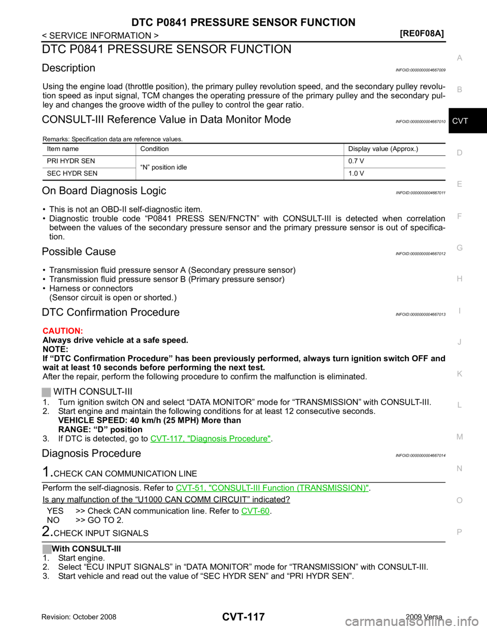
DTC P0841 PRESSURE SENSOR FUNCTION
Description INFOID:0000000004667009
Using the engine load (throttle position), the primary pulley revolution speed, and the secondary pulley revolu-
tion speed as input signal, TCM changes the operating pr essure of the primary pulley and the secondary pul-
ley and changes the groove width of the pulley to control the gear ratio.
CONSULT-III Reference Val ue in Data Monitor Mode INFOID:0000000004667010
Remarks: Specification data are reference values.
On Board Diagnosis Logic INFOID:0000000004667011
• This is not an OBD-II self-diagnostic item.
• Diagnostic trouble code “P0841 PRESS SEN/FNCTN” wit h CONSULT-III is detected when correlation
between the values of the secondary pressure sensor and the primary pressure sensor is out of specifica-
tion.
Possible Cause INFOID:0000000004667012
• Transmission fluid pressure sensor A (Secondary pressure sensor)
• Transmission fluid pressure sensor B (Primary pressure sensor)
• Harness or connectors
(Sensor circuit is open or shorted.)
DTC Confirmation Procedure INFOID:0000000004667013
CAUTION:
Always drive vehicle at a safe speed.
NOTE:
If “DTC Confirmation Procedure” has been previously performed, alw ays turn ignition switch OFF and
wait at least 10 seconds before performing the next test.
After the repair, perform the following procedure to confirm the malfunction is eliminated.
WITH CONSULT-III
1. Turn ignition switch ON and select “DATA MO NITOR” mode for “TRANSMISSION” with CONSULT-III.
2. Start engine and maintain the following conditions for at least 12 consecutive seconds.
VEHICLE SPEED: 40 km/h (25 MPH) More than
RANGE: “D” position
3. If DTC is detected, go to CVT-117, " Diagnosis Procedure " .
Diagnosis Procedure INFOID:0000000004667014CONSULT-III Function (TRANSMISSION) " .
Is any malfunction of the “ U1000 CAN COMM CIRCUIT ” indicated?
YES >> Check CAN communication line. Refer to
CVT-60 .
NO >> GO TO 2.
Page 1063 of 4331

CVT
N
O P
DTC P0845 TRANSMISSION FLUID PR
ESSURE SENSOR B CIRCUIT (PRI
PRESSURE SENSOR)
Description INFOID:0000000004667015
• The transmission fluid pressure sensor B (primary pre ssure sensor) is included in the control valve assem-
bly.
• The transmission fluid pressure sensor B (primary pr essure sensor) detects primary pressure of CVT and
sends TCM the signal.
CONSULT-III Reference Val ue in Data Monitor Mode INFOID:0000000004667016
Remarks: Specification data are reference values.
On Board Diagnosis Logic INFOID:0000000004667017
• This is an OBD-II self-diagnostic item.
• Diagnostic trouble code “P0845 TR PRS SENS/B CIRC” wi th CONSULT-III is detected under the following
conditions.
- When TCM detects an improper voltage drop when it receives the sensor signal.
- When TCM compares target value with monitor value and detects an irregularity.
Possible Cause INFOID:0000000004667018
• Transmission fluid pressure sensor B (Primary pressure sensor)
• Harness or connectors (Sensor circuit is open or shorted.)
DTC Confirmation Procedure INFOID:0000000004667019
NOTE:
If “DTC Confirmation Procedure” has been previously performed, alw ays turn ignition switch OFF and
wait at least 10 seconds before performing the next test.
After the repair, perform the following procedure to confirm the malfunction is eliminated.
WITH CONSULT-III
1. Turn ignition switch ON and select “DATA MO NITOR” mode for “TRANSMISSION” with CONSULT-III.
2. Make sure that output voltage of line te mperature sensor is within the range below.
ATF TEMP SEN: 1.0 - 2.0 V
If out of range, drive the vehicle to decrease the voltage (warm up the fluid) or stop engine to
increase the voltage (c ool down the fluid)
3. Start engine and wait for at least 5 consecutive seconds.
4. If DTC is detected, go to CVT-121, " Diagnosis Procedure " .
WITH GST
Follow the procedure “WITH CONSULT-III”. Item name Condition Display value (Approx.)
PRI HYDR SEN “N” position idle 0.7 V