refrigerant type NISSAN TIIDA 2009 Service Service Manual
[x] Cancel search | Manufacturer: NISSAN, Model Year: 2009, Model line: TIIDA, Model: NISSAN TIIDA 2009Pages: 4331, PDF Size: 58.04 MB
Page 2886 of 4331
![NISSAN TIIDA 2009 Service Service Manual EC-1530< SERVICE INFOMATION >
[MR TYPE 2]
REFRIGERANT PRESSURE SENSOR
1. Disconnect refrigerant pressure sensor (1) harness connector.
- : Vehicle front
2. Turn ignition switch ON.
3. Check voltage](/img/5/57398/w960_57398-2885.png "NISSAN TIIDA 2009 Service Service Manual EC-1530< SERVICE INFOMATION >
[MR TYPE 2]
REFRIGERANT PRESSURE SENSOR
1. Disconnect refrigerant pressure sensor (1) harness connector.
- : Vehicle front
2. Turn ignition switch ON.
3. Check voltage")
EC-1530< SERVICE INFOMATION >
[MR TYPE 2]
REFRIGERANT PRESSURE SENSOR
1. Disconnect refrigerant pressure sensor (1) harness connector.
- : Vehicle front
2. Turn ignition switch ON.
3. Check voltage between refrigerant pressure sensor terminal 3 and ground with CONSULT-III or tester.
OK or NG OK >> GO TO 5.
NG >> GO TO 4. 4.
DETECT MALFUNCTIONING PART
Check the following.
• Harness connectors E8, F8
• Harness for open or short between refrigerant pressure sensor and ECM
>> Repair open circuit or short to ground or short to power in harness or connectors. 5.
CHECK REFRIGERANT PRESSURE SENSOR GROUND CIRCUIT FOR OPEN AND SHORT
1. Turn ignition switch OFF.
2. Disconnect ECM harness connector.
3. Check harness continuity between refrigerant pressure sensor terminal 1 and ECM terminal 48.
Refer to Wiring Diagram.
4. Also check harness for short to ground and short to power.
OK or NG OK >> GO TO 7.
NG >> GO TO 6. 6.
DETECT MALFUNCTIONING PART
Check the following.
• Harness connectors E8, F8
• Harness for open or short between refrigerant pressure sensor and ECM
>> Repair open circuit or short to ground or short to power in harness or connectors. 7.
CHECK REFRIGERANT PRESSURE SENSOR INPU T SIGNAL CIRCUIT FOR OPEN AND SHORT
1. Check harness continuity between refrigerant pressure sensor terminal 2 and ECM terminal 41. Refer to Wiring Diagram.
2. Also check harness for short to ground and short to power.
OK or NG BBIA0713E
Voltage: Approximately 5V
SEF479Y
Continuity should exist.
Continuity should exist.
Page 3890 of 4331
MTC
N
O P
been shown to be combustible at
elevated pressures. These mixtures, if ignited, may cause injury or
property damage. Additional health and safety info rmation may be obtained from refrigerant manu-
facturers.
Oil Precaution INFOID:0000000004307045
• Use only specified oil for the HFC-134a (R-134a) A/C system and HFC-134a (R-134a) components. If oil
other than that specified is used, comp ressor malfunction is likely to occur.
• The specified HFC-134a (R-134a) oil rapidly absorbs mo isture from the atmosphere. The following handling
precautions must be observed:
- When removing refrigerant components from a vehicle, immediately cap (seal) the component to minimize the entry of moisture from the atmosphere.
- When installing refrigerant components to a vehicle, do not remove the caps (unseal) until just before con- necting the components. Connect all refrigerant loop components as quickly as possible to minimize the
entry of moisture into system.
- Only use the specified oil from a sealed container. Imm ediately reseal containers of oil. Without proper seal-
ing, oil will become moisture saturated and should not be used.
• Avoid breathing A/C refrigerant and oil vapor or mist. Exposure may irritate eyes, nose and throat.
Use only approved recovery/recycling equipment to discharge HFC-134a (R-134a) refrigerant. If accidental
system discharge occurs, ventilate work area before re suming service. Additional health and safety informa-
tion may be obtained from refrigerant and oil manufacturers.
• Do not allow A/C oil to come in contact with styrofoam parts. Damage may result.
Precaution for Refrigerant Connection INFOID:0000000004307046
A new type refrigerant connection has been introduced to a ll refrigerant lines except the following location.
• Expansion valve to evaporator
• Refrigerant pressure sensor to condenser
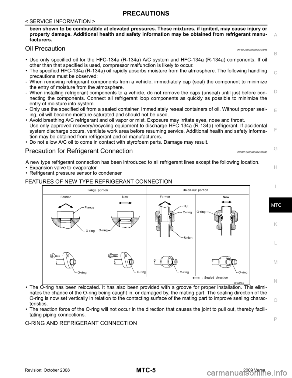
FEATURES OF NEW TYPE REFRIGERANT CONNECTION
• The O-ring has been relocated. It has also been provided with a groove for proper installation. This elimi- nates the chance of the O-ring being caught in, or damaged by, the mating part. The sealing direction of the
O-ring is now set vertically in relation to the contacti ng surface of the mating part to improve sealing charac-
teristics.
• The reaction force of the O-ring will not occur in the dire ction that causes the joint to pull out, thereby facili-
tating piping connections.
O-RING AND REFRIGERANT CONNECTION
Page 3892 of 4331
MTC
N
O P
O-Ring Part Numbers and Specifications
CAUTION:
When replacing or cleaning refrigerant cycle components, observe the following.
• When the compressor is removed, store it in the sam e position as it is when installed on the vehicle.
Doing so will cause oil to en ter the low-pressure chamber.
• When connecting tubes, always use a to rque wrench and a back-up wrench.
• After disconnecting tubes, immediately plug all op enings to prevent entry of dirt and moisture.
• When installing an air conditione r in the vehicle, connect the pipes as the final stage of the opera-
tion. Do not remove the seal caps of pipes and other components until just before required for con-
nection.
• Allow components stored in cool areas to warm to working area temperature before removing seal
caps. This prevents condensation from forming inside A/C components.
• Thoroughly remove moisture from the refriger ation system before charging the refrigerant.
• Always replace used O-rings.
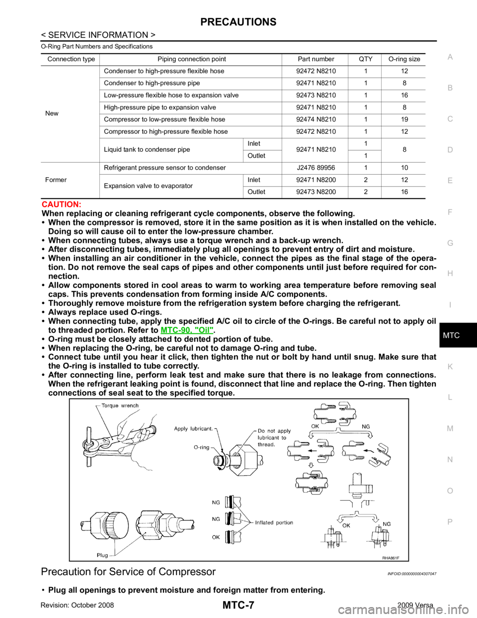
• When connecting tube, apply the speci fied A/C oil to circle of the O-rings. Be careful not to apply oil
to threaded portion. Refer to MTC-90, " Oil " .
• O-ring must be closely attached to dented portion of tube.
• When replacing the O-ring, be careful not to damage O-ring and tube.
• Connect tube until you hear it cl ick, then tighten the nut or bolt by hand until snug. Make sure that
the O-ring is installed to tube correctly.
• After connecting line, perform leak test and make sure that there is no leakage from connections.
When the refrigerant leaking point is found, disconnect that line and replace the O-ring. Then tighten
connections of seal seat to the specified torque.
Precaution for Service of Compressor INFOID:0000000004307047
• Plug all openings to prevent moisture and foreign matter from entering.
Connection type Piping connection point Part number QTY O-ring size
New Condenser to high-pressure flexible hose 92472 N8210 1 12
Condenser to high-pressure pipe 92471 N8210 1 8
Low-pressure flexible hose to expansion valve 92473 N8210 1 16
High-pressure pipe to expansion valve 92471 N8210 1 8
Compressor to low-pressure flexible hose 92474 N8210 1 19
Compressor to high-pressure flexible hose 92472 N8210 1 12
Liquid tank to condenser pipe Inlet
92471 N8210 1
8
Outlet 1
Former Refrigerant pressure sensor to condenser J2476 89956 1 10
Expansion valve to evaporator Inlet 92471 N8200 2 12
Outlet 92473 N8200 2 16
Page 3896 of 4331
MTC
N
O P
PREPARATION
HFC-134a (R-134a) Servic e Tool and Equipment INFOID:0000000004307051
Never mix HFC-134a refrigerant and/or its specified oil with CFC-12 (R-12) refrigerant and/or its oil.
Separate and non-interchangeable service equipment must be used for handling each type of refrigerant/oil.
Refrigerant container fittings, service hose fittings and service equipment fittings (equipment which handles
refrigerant and/or oil) are different between CFC-12 (R-12) and HFC-134a (R-134a). This is to avoid mixed
use of the refrigerants/oil.
Adapters that convert one size fitting to another must never be used refrigerant/oil contamination will occur
and compressor failure will result.
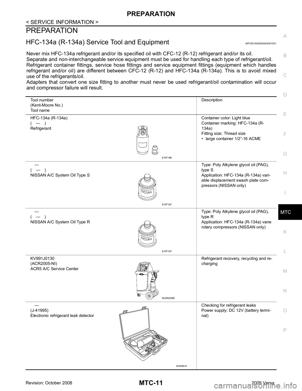
Tool number
(Kent-Moore No.)
Tool name Description
HFC-134a (R-134a)
( — )
Refrigerant Container color: Light blue
Container marking: HFC-134a (R-
134a)
Fitting size: Thread size
• large container 1/2”-16 ACME
—
( — )
NISSAN A/C System Oil Type S Type: Poly Alkylene glycol oil (PAG),
type S
Application: HFC-134a (R-134a) vari-
able displacement swash plate com-
pressors (NISSAN only)
—
( — )
NISSAN A/C System Oil Type R Type: Poly Alkylene glycol oil (PAG),
type R
Application: HFC-134a (R-134a) vane
rotary compressors (NISSAN only)
KV991J0130
(ACR2005-NI)
ACR5 A/C Se rvice Center Refrigerant recovery, recycling and re-
charging
—
(J-41995)
Electronic refrigerant leak detector Checking for refrigerant leaks
Power supply: DC 12V (battery termi-
nal) S-NT197
WJIA0293E
AHA281A
Page 3902 of 4331

MTC
N
O P
OIL
Maintenance of Oil Qu antity in Compressor INFOID:0000000004307056
The oil in the compressor circulates through the system with the refrigerant. Add oil to compressor when
replacing any component or after a lar ge refrigerant leakage occurred. It is important to maintain the specified
amount.
If oil quantity is not maintained properly , the following malfunctions may result:
• Lack of oil: May lead to a seized compressor.
• Excessive oil: Inadequate cooling (thermal exchange interference)
OIL
OIL ADJUSTING PROCEDURE FOR COMPONENTS REPLACEMENT EXCEPT COMPRESSOR After replacing any of the following major component s, add the correct amount of oil to the system.
Amount Of Oil To Be Added
*1: If refrigerant leak is small, no addition of oil is needed.
OIL ADJUSTING PROCEDURE FOR COMPRESSOR REPLACEMENT TYPE 1 Compressor (CR-10) : NISSAN A/C System Oil Type R
TYPE 2 Compressor (CSV511) : NI SSAN A/C System Oil Type S
Part replaced Oil to be added to system
Remarks
Amount of oil
m (US fl oz, Imp fl oz)
Evaporator 35 (1.2, 1.2) -
Condenser 15 (0.5, 0.5) -
Liquid tank 5 (0.2, 0.2) -
In case of refrigerant leak 30 (1.0, 1.1) Large leak
None *1 Small leak *1
Page 3942 of 4331

MTC
N
O P
THERMO CONTROL AMPLIFIER
Removal and Installation INFOID:0000000004307078
NOTE:
Only MR18DE - TYPE 2 systems are equipped with a thermo control amplifier.
REMOVAL 1. Remove evaporator. Refer to MTC-85, " Removal and Installation of Evaporator " .
CAUTION:
Cap or wrap the joint of the pipe with suitable ma terial such as vinyl tape to avoid the entry of air.
2. Mark the mounting position of the thermo control amp. and then remove thermo control amp. (1) from evaporator (2).
INSTALLATION Installation is in the reverse order of removal.
CAUTION:
• Replace O-rings for A/C piping with new on es, and apply compressor oil when installing.
• Install the thermo control amp. at the mark made during removal of the thermo control amp.
• When recharging refrigerant, check for leaks.
Page 3944 of 4331
MTC
N
O P
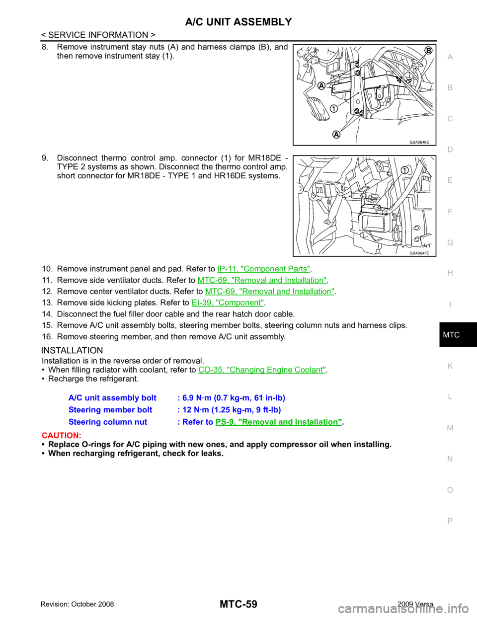
8. Remove instrument stay nuts (A) and harness clamps (B), and
then remove instrument stay (1).
9. Disconnect thermo control amp. connector (1) for MR18DE - TYPE 2 systems as shown. Disconnect the thermo control amp.
short connector for MR18DE - TYPE 1 and HR16DE systems.
10. Remove instrument panel and pad. Refer to IP-11, " Component Parts " .
11. Remove side ventilator ducts. Refer to MTC-69, " Removal and Installation " .
12. Remove center ventilator ducts. Refer to MTC-69, " Removal and Installation " .
13. Remove side kicking plates. Refer to EI-39, " Component " .
14. Disconnect the fuel filler door cable and the rear hatch door cable.
15. Remove A/C unit assembly bolts, steering member bolts, steering column nuts and harness clips.
16. Remove steering member, and then remove A/C unit assembly.
INSTALLATION Installation is in the reverse order of removal.
• When filling radiator with coolant, refer to CO-35, " Changing Engine Coolant " .
• Recharge the refrigerant.
CAUTION:
• Replace O-rings for A/C piping with new on es, and apply compressor oil when installing.
• When recharging refrigerant, check for leaks. Removal and Installation " .