stop start NISSAN TIIDA 2009 Service Service Manual
[x] Cancel search | Manufacturer: NISSAN, Model Year: 2009, Model line: TIIDA, Model: NISSAN TIIDA 2009Pages: 4331, PDF Size: 58.04 MB
Page 1388 of 4331
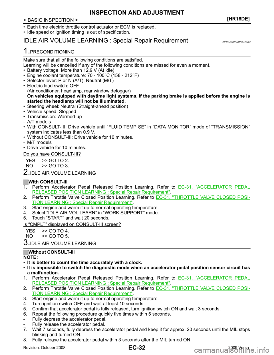
YES >> GO TO 2.
NO >> GO TO 3. ACCELERATOR PEDAL
RELEASED POSITION LEARNING : Special Repair Requirement " .
2. Perform Throttle Valve Closed Position Learning. Refer to EC-31, " THROTTLE VALVE CLOSED POSI-
TION LEARNING : Special Repair Requirement " .
3. Start engine and warm it up to normal operating temperature.
4. Select “IDLE AIR VOL LEARN” in “WORK SUPPORT” mode.
5. Touch “START” and wait 20 seconds.
Is “ CMPLT ” displayed on CONSULT-III screen?
YES >> GO TO 4.
NO >> GO TO 5. ACCELERATOR PEDAL
RELEASED POSITION LEARNING : Special Repair Requirement " .
2. Perform Throttle Valve Closed Position Learning. Refer to EC-31, " THROTTLE VALVE CLOSED POSI-
TION LEARNING : Special Repair Requirement " .
3. Start engine and warm it up to normal operating temperature.
4. Turn ignition switch OFF and wait at least 10 seconds.
5. Confirm that accelerator pedal is fully releas ed, turn ignition switch ON and wait 3 seconds.
6. Repeat the following procedure quickly five times within 5 seconds.
- Fully depress the accelerator pedal.
- Fully release the accelerator pedal.
7. Wait 7 seconds, fully depress the accelerator pedal and keep it for approx. 20 seconds until the MIL stops
blinking and turned ON.
8. Fully release the accelerator pedal within 3 seconds after the MIL turned ON.
Page 1399 of 4331
EC
NP
O
*3: ECM determines the start signal status by the signals of engine speed and battery voltage.
SYSTEM DESCRIPTION The amount of fuel injected from the fuel injector is determined by the ECM. The ECM controls the length of
time the valve remains open (injection pulse duration). T he amount of fuel injected is a program value in the
ECM memory. The program value is preset by engi ne operating conditions. These conditions are determined
by input signals (for engine speed and intake air) from t he crankshaft position sensor (POS), camshaft position
sensor (PHASE) and the mass air flow sensor.
VARIOUS FUEL INJECTION INCREASE/DECREASE COMPENSATION In addition, the amount of fuel injected is compens ated to improve engine performance under various operat-
ing conditions as listed below.
• During warm-up
• When starting the engine
• During acceleration
• Hot-engine operation
• When selector lever is changed from N to D (A/T models)
• High-load, high-speed operation
• During deceleration
• During high engine speed operation
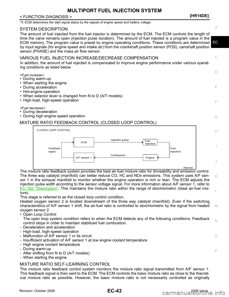
MIXTURE RATIO FEEDBACK CONTROL (CLOSED LOOP CONTROL)
The mixture ratio feedback system prov ides the best air-fuel mixture ratio for driveability and emission control.
The three way catalyst (manifold) can better reduce CO, HC and NOx emissions. This system uses A/F sen-
sor 1 in the exhaust manifold to monitor whether the engine operation is rich or lean. The ECM adjusts the
injection pulse width according to the sensor voltage si gnal. For more information about A/F sensor 1, refer to
EC-182, " Description " . This maintains the mixture ratio within t
he range of stoichiometric (ideal air-fuel mix-
ture).
This stage is referred to as the closed loop control condition.
Heated oxygen sensor 2 is located downstream of the th ree way catalyst (manifold). Even if the switching
characteristics of A/F sensor 1 shift, the air-fuel rati o is controlled to stoichiometric by the signal from heated
oxygen sensor 2.
• Open Loop Control
The open loop system condition refers to when the EC M detects any of the following conditions. Feedback
control stops in order to maintain stabilized fuel combustion.
- Deceleration and acceleration
- High-load, high-speed operation
- Malfunction of A/F sensor 1 or its circuit
- Insufficient activation of A/F sensor 1 at low engine coolant temperature
- High engine coolant temperature
- During warm-up
- After shifting from N to D (A/T models)
- When starting the engine
MIXTURE RATIO SELF-LEARNING CONTROL The mixture ratio feedback control system monitors the mixture ratio signal transmitted from A/F sensor 1.
This feedback signal is then sent to the ECM. The ECM cont rols the basic mixture ratio as close to the theoret-
ical mixture ratio as possible. However, the basic mi xture ratio is not necessarily controlled as originally
Page 1461 of 4331

EC
NP
O
*1: This item includes 1st trip DTCs.
*2: This mode includes 1st trip freeze frame data or freeze fr ame data. The items appear on CONSULT-III screen in freeze frame data
mode only if a 1st trip DTC or DTC is detected. For details, refer to EC-90, " Diagnosis Description " .
*3: Always “CMPLT ” is displayed.
WORK SUPPORT MODE
Work Item
*: This function is not necessary in the usual service procedure.
SELF DIAGNOSTIC RESULT MODE
Self Diagnostic Item Regarding items of DTC and 1st trip DTC, refer to EC-475, " DTC Index " .)
Freeze Frame Data and 1st Trip Freeze Frame Data WORK ITEM CONDITION USAGE
FUEL PRESSURE RELEASE • FUEL PUMP WILL STOP BY TOUCHING “START” DUR- ING IDLING.
CRANK A FEW TIMES AFTER ENGINE STALLS. When releasing fuel pressure from
fuel line
IDLE AIR VOL LEARN • THE IDLE AIR VOLUME THAT KEEPS THE ENGINE WITHIN THE SPECIFIED RANGE IS MEMORIZED IN
ECM. When learning the idle air volume
SELF-LEARNING CONT • THE COEFFICI ENT OF SELF-LEARNING CONTROL
MIXTURE RATIO RETURNS TO THE ORIGINAL COEF-
FICIENT. When clearing mixture ratio self-
learning value
EVAP SYSTEM CLOSE CLOSE THE EVAP CANISTER VENT CONTROL VALVE IN ORDER TO MAKE EVAP SYSTEM CLOSE UNDER THE
FOLLOWING CONDITIONS.
• IGN SW ON
• ENGINE NOT RUNNING
• AMBIENT TEMPERATURE IS ABOVE 0 °C (32 °F).
• NO VACUUM AND NO HIGH PRESSURE IN EVAP SYS- TEM
• FUEL TANK TEMP. IS MORE THAN 0 °C (32 °F).
• WITHIN 10 MINUTES AFTER STARTING “EVAP SYS- TEM CLOSE”
• WHEN TRYING TO EXECUTE “EVAP SYSTEM CLOSE”
UNDER THE CONDITION EXCEPT ABOVE, CONSULT-
II WILL DISCONTINUE IT AND DISPLAY APPROPRIATE
INSTRUCTION.
NOTE:
WHEN STARTING ENGINE, CONSULT-III MAY DIS-
PLAY “BATTERY VOLTAGE IS LOW. CHARGE BAT-
TERY”, EVEN IN USING CHARGED BATTERY. When detecting EVAP vapor leak
point of EVAP system
VIN REGISTRATION • IN THIS MODE, VIN IS REGIST ERED IN ECM. When registering VIN in ECM
TARGET IDLE RPM ADJ* • IDLE CONDITION When setting target idle speed
TARGET IGN TIM ADJ* • IDLE CONDITION When adjusting target ignition timingFreeze frame data
item* Description
DIAG TROUBLE
CODE
[PXXXX] • The engine control co
mponent part/control system has a trouble code, it is displayed as PXXXX. (Refer to
EC-475, " DTC Index " .)
FUEL SYS-B1 • “Fuel injection system status” at the moment a malfunction is detected is displayed.
• One mode in the following is displayed. Mode2: Open loop due to detected system malfunction
Mode3: Open loop due to driving conditions (power enrichment, deceleration enleanment)
Mode4: Closed loop - using oxygen sensor(s) as feedback for fuel control
Mode5: Open loop - has not yet satisfied condition to go to closed loop
Page 1463 of 4331

EC
NP
O
HO2S2 (B1) V
• The signal voltage of the heated oxygen sensor 2 is
displayed.
HO2S2 MNTR(B1) RICH/
LEAN • Display of heated oxygen sensor 2 signal:
RICH: means the amount of oxygen after three way
catalyst is relatively small.
LEAN: means the amount of oxygen after three way
catalyst is relatively large. • When the engine is stopped, a certain
value is indicated.
VHCL SPEED SE km/h or
mph • The vehicle speed computed from the vehicle speed
signal sent from combination meter is displayed.
BATTERY VOLT V • The power supply voltage of ECM is displayed.
ACCEL SEN 1 V• The accelerator pedal position sensor signal voltage is
displayed. • ACCEL SEN 2 signal is converted by
ECM internally. Thus, it differs from
ECM terminal voltage signal.
ACCEL SEN 2
TP SEN 1-B1 V• The throttle position sensor signal voltage is dis-
played. • TP SEN 2-B1 signal is converted by
ECM internally. Thus, it differs from
ECM terminal voltage signal.
TP SEN 2-B1
FUEL T/TMP SE °C or °F • The fuel temperature (determined by the signal volt-
age of the fuel tank temperature sensor) is displayed.
INT/A TEMP SE °C or °F • The intake air temperature (determined by the signal
voltage of the intake air temperature sensor) is indicat-
ed.
EVAP SYS PRES V • The signal voltage of EVAP control system pressure
sensor is displayed.
FUEL LEVEL SE V • The signal voltage of the fuel level sensor is displayed.
START SIGNAL ON/OFF • Indicates start signal status [ON/OFF] computed by
the ECM according to the signals of engine speed and
battery voltage. • After starting the engine, [OFF] is dis-
played regardless of the starter sig-
nal.
CLSD THL POS ON/OFF • Indicates idle position [ON/OFF] computed by ECM
according to the accelerator pedal position sensor sig-
nal.
AIR COND SIG ON/OFF • Indicates [ON/OFF] condition of the air conditioner
switch determined by the air conditioner ON signal.
P/N POSI SW ON/OFF • Indicates [ON/OFF] condit
ion from the park/neutral
position (PNP) switch signal.
PW/ST SIGNAL ON/OFF • [ON/OFF] condition of the power steering system (de-
termined by the signal sent from EPS control unit) is
indicated.
LOAD SIGNAL ON/OFF • Indicates [ON/OFF] condition from the electrical load
signal.
ON: Rear window defogger switch is ON and/or light-
ing switch is in 2nd position.
OFF: Both rear window defogger switch and lighting
switch are OFF.
IGNITION SW ON/OFF • Indicates [ON/OFF] condition from ignition switch sig-
nal.
HEATER FAN SW ON/OFF • Indicates [ON/OFF] condition from the heater fan
switch signal.
BRAKE SW ON/OFF • Indicates [ON/OFF] condition from the stop lamp
switch signal.
INJ PULSE-B1 msec • Indicates the actual fuel injection pulse width compen-
sated by ECM according to the input signals. • When the engine is stopped, a certain
computed value is indicated.
IGN TIMING BTDC • Indicates the ignition timing computed by ECM ac-
cording to the input signals. • When the engine is stopped, a certain
value is indicated.
CAL/LD VALUE % • “Calculated load value” indicates the value of the cur-
rent air flow divided by peak air flow.
Monitored item Unit Description Remarks
Page 1511 of 4331
![NISSAN TIIDA 2009 Service Service Manual P0101 MAF SENSOR
EC-155
< COMPONENT DIAGNOSIS >
[HR16DE] C
D E
F
G H
I
J
K L
M A EC
NP
O
3. Check the voltage between ECM harness connector and
ground.
*: Check for linear voltage rise in respo](/img/5/57398/w960_57398-1510.png "NISSAN TIIDA 2009 Service Service Manual P0101 MAF SENSOR
EC-155
< COMPONENT DIAGNOSIS >
[HR16DE] C
D E
F
G H
I
J
K L
M A EC
NP
O
3. Check the voltage between ECM harness connector and
ground.
*: Check for linear voltage rise in respo")
P0101 MAF SENSOR
EC-155
< COMPONENT DIAGNOSIS >
[HR16DE] C
D E
F
G H
I
J
K L
M A EC
NP
O
3. Check the voltage between ECM harness connector and
ground.
*: Check for linear voltage rise in response to engine being increased to about 4,000 rpm.
Is the inspection result normal? YES >> INSPECTION END
NO >> GO TO 4. 4.
CHECK MASS AIR FLOW SENSOR-III
With CONSULT-III
1. Turn ignition switch OFF.
2. Disconnect mass air flow sensor har ness connector and reconnect it again.
3. Start engine and warm it up to normal operating temperature.
4. Connect CONSULT-III and select “DATA MONITOR” mode.
5. Select “MAS A/F SE-B1” and check indication.
*: Check for linear voltage rise in response to engine being increased to about 4,000 rpm.
Without CONSULT-III
1. Turn ignition switch OFF.
2. Disconnect mass air flow sensor har ness connector and reconnect it again.
3. Start engine and warm it up to normal operating temperature.
4. Check the voltage between ECM harness connector and ground.
*: Check for linear voltage rise in response to engine being increased to about 4,000 rpm.
Is the inspection result normal? YES >> INSPECTION END
NO >> Clean or replace mass air flow sensor. ECM
Ground Condition Voltage
Con-
nector Termi-
nal
F11 45
(MAF
sensor
signal) Ground Ignition switch ON (Engine stopped.) Approx. 0.4 V
Idle (Engine is wa rmed-up to normal
operating temperature.) 0.9 - 1.3 V
2,500 rpm (Engine is warmed-up to
normal operating temperature.) 1.4 - 1.9 V
Idle to about 4,000 rpm 0.9 - 1.3 V to
Approx. 2.4 V* PBIA9564J
Monitor item Condition MAS A/F SE-B1
MAS A/F SE-B1 Ignition switch ON (Engine stopped.) Approx. 0.4 V
Idle (Engine is warmed-up to normal operating temperature.) 0.9 - 1.3 V
2,500 rpm (Engine is warmed-up to normal operating temperature.) 1.4 - 1.9 V
Idle to about 4,000 rpm 0.9 - 1.3 V to Approx. 2.4 V*
ECM Ground Condition Voltage
Con-
nector Termi-
nal
F11 45
(MAF
sensor
signal) Ground Ignition switch ON (Engine stopped.) Approx. 0.4 V
Idle (Engine is wa rmed-up to normal
operating temperature.) 0.9 - 1.3 V
2,500 rpm (Engine is warmed-up to
normal operating temperature.) 1.4 - 1.9 V
Idle to about 4,000 rpm 0.9 - 1.3 V to
Approx. 2.4 V* PBIA9564J
Page 1515 of 4331
![NISSAN TIIDA 2009 Service Service Manual P0102, P0103 MAF SENSOR
EC-159
< COMPONENT DIAGNOSIS >
[HR16DE] C
D E
F
G H
I
J
K L
M A EC
NP
O
2. Also check harness for short to ground and short to power.
Is the inspection result normal? YES >> GO](/img/5/57398/w960_57398-1514.png "NISSAN TIIDA 2009 Service Service Manual P0102, P0103 MAF SENSOR
EC-159
< COMPONENT DIAGNOSIS >
[HR16DE] C
D E
F
G H
I
J
K L
M A EC
NP
O
2. Also check harness for short to ground and short to power.
Is the inspection result normal? YES >> GO")
P0102, P0103 MAF SENSOR
EC-159
< COMPONENT DIAGNOSIS >
[HR16DE] C
D E
F
G H
I
J
K L
M A EC
NP
O
2. Also check harness for short to ground and short to power.
Is the inspection result normal? YES >> GO TO 8.
NO >> Repair open circuit or short to ground or short to power in harness or connectors. 8.
CHECK MASS AIR FLOW SENSOR
Refer to EC-159, " Component Inspection " .
Is the inspection result normal? YES >> GO TO 9.
NO >> Replace mass air flow sensor. 9.
CHECK INTERMITTENT INCIDENT
Refer to EC-120, " Diagnosis Procedure " .
>> INSPECTION END
Component Inspection INFOID:00000000047800781.
CHECK MASS AIR FLOW SENSOR-I
With CONSULT-III
1. Turn ignition switch OFF.
2. Reconnect all harness connectors disconnected.
3. Start engine and warm it up to normal operating temperature.
4. Connect CONSULT-III and select “DATA MONITOR” mode.
5. Select “MAS A/F SE-B1” and check indication.
*: Check for linear voltage rise in response to engine being increased to about 4,000 rpm.
Without CONSULT-III
1. Turn ignition switch OFF.
2. Reconnect all harness connectors disconnected.
3. Start engine and warm it up to normal operating temperature.
4. Check the voltage between ECM harness connector and ground. MAF sensor ECM
Continuity
Connector Terminal Connector Terminal
F31 4 F11 45 Existed Monitor item Condition MAS A/F SE-B1
MAS A/F SE-B1 Ignition switch ON (Engine stopped.) Approx. 0.4 V
Idle (Engine is warmed-up to normal operating temperature.) 0.9 - 1.3 V
2,500 rpm (Engine is warmed-up to normal operating temperature.) 1.4 - 1.9 V
Idle to about 4,000 rpm 0.9 - 1.3 V to Approx. 2.4 V*
ECM Ground Condition Voltage
Con-
nector Termi-
nal
F11 45
(MAF
sensor signal) Ground Ignition switch ON (Engine stopped.) Approx. 0.4 V
Idle (Engine is wa rmed-up to normal
operating temperature.) 0.9 - 1.3 V
2,500 rpm (Engine is warmed-up to
normal operating temperature.) 1.4 - 1.9 V
Idle to about 4,000 rpm 0.9 - 1.3 V to
Approx. 2.4 V* PBIA9564J
Page 1516 of 4331
![NISSAN TIIDA 2009 Service Service Manual EC-160< COMPONENT DIAGNOSIS >
[HR16DE]
P0102, P0103 MAF SENSOR
*: Check for linear voltage rise in response to engine being increased to about 4,000 rpm.
Is the inspection result normal? YES >> INSPEC](/img/5/57398/w960_57398-1515.png "NISSAN TIIDA 2009 Service Service Manual EC-160< COMPONENT DIAGNOSIS >
[HR16DE]
P0102, P0103 MAF SENSOR
*: Check for linear voltage rise in response to engine being increased to about 4,000 rpm.
Is the inspection result normal? YES >> INSPEC")
EC-160< COMPONENT DIAGNOSIS >
[HR16DE]
P0102, P0103 MAF SENSOR
*: Check for linear voltage rise in response to engine being increased to about 4,000 rpm.
Is the inspection result normal? YES >> INSPECTION END
NO >> GO TO 2. 2.
CHECK FOR THE CAUSE OF UNEVEN AIR FL OW THROUGH MASS AIR FLOW SENSOR
1. Turn ignition switch OFF.
2. Check for the cause of uneven air flow through mass air flow sensor. Refer to the following.
- Crushed air ducts
- Malfunctioning seal of air cleaner element
- Uneven dirt of air cleaner element
- Improper specification of intake air system parts
Is the inspection result normal? YES >> GO TO 4.
NO >> GO TO 3. 3.
CHECK MASS AIR FLOW SENSOR-II
With CONSULT-III
1. Repair or replace malfunctioning part.
2. Start engine and warm it up to normal operating temperature.
3. Connect CONSULT-III and select “DATA MONITOR” mode.
4. Select “MAS A/F SE-B1” and check indication.
*: Check for linear voltage rise in response to engine being increased to about 4,000 rpm.
Without CONSULT-III
1. Repair or replace malfunctioning part.
2. Start engine and warm it up to normal operating temperature.
3. Check the voltage between ECM harness connector and
ground.
*: Check for linear voltage rise in response to engine being increased to about 4,000 rpm.
Is the inspection result normal? YES >> INSPECTION END
NO >> GO TO 4. 4.
CHECK MASS AIR FLOW SENSOR-III
With CONSULT-III
1. Turn ignition switch OFF.
2. Disconnect mass air flow sensor harness connector and reconnect it again.
3. Start engine and warm it up to normal operating temperature. Monitor item Condition MAS A/F SE-B1
MAS A/F SE-B1 Ignition switch ON (Engine stopped.) Approx. 0.4 V
Idle (Engine is warmed-up to normal operating temperature.) 0.9 - 1.3 V
2,500 rpm (Engine is warmed-up to normal operating temperature.) 1.4 - 1.9 V
Idle to about 4,000 rpm 0.9 - 1.3 V to Approx. 2.4 V*
ECM Ground Condition Voltage
Con-
nector Termi-
nal
F11 45
(MAF
sensor
signal) Ground Ignition switch ON (Engine stopped.) Approx. 0.4 V
Idle (Engine is wa rmed-up to normal
operating temperature.) 0.9 - 1.3 V
2,500 rpm (Engine is warmed-up to
normal operating temperature.) 1.4 - 1.9 V
Idle to about 4,000 rpm 0.9 - 1.3 V to
Approx. 2.4 V* PBIA9564J
Page 1517 of 4331
![NISSAN TIIDA 2009 Service Service Manual P0102, P0103 MAF SENSOR
EC-161
< COMPONENT DIAGNOSIS >
[HR16DE] C
D E
F
G H
I
J
K L
M A EC
NP
O
4. Connect CONSULT-III and select “DATA MONITOR” mode.
5. Select “MAS A/F SE-B1” and check indic](/img/5/57398/w960_57398-1516.png "NISSAN TIIDA 2009 Service Service Manual P0102, P0103 MAF SENSOR
EC-161
< COMPONENT DIAGNOSIS >
[HR16DE] C
D E
F
G H
I
J
K L
M A EC
NP
O
4. Connect CONSULT-III and select “DATA MONITOR” mode.
5. Select “MAS A/F SE-B1” and check indic")
P0102, P0103 MAF SENSOR
EC-161
< COMPONENT DIAGNOSIS >
[HR16DE] C
D E
F
G H
I
J
K L
M A EC
NP
O
4. Connect CONSULT-III and select “DATA MONITOR” mode.
5. Select “MAS A/F SE-B1” and check indication.
*: Check for linear voltage rise in response to engine being increased to about 4,000 rpm.
Without CONSULT-III
1. Turn ignition switch OFF.
2. Disconnect mass air flow sensor har ness connector and reconnect it again.
3. Start engine and warm it up to normal operating temperature.
4. Check the voltage between ECM harness connector and ground.
*: Check for linear voltage rise in response to engine being increased to about 4,000 rpm.
Is the inspection result normal? YES >> INSPECTION END
NO >> Clean or replace mass air flow sensor. Monitor item Condition MAS A/F SE-B1
MAS A/F SE-B1 Ignition switch ON (Engine stopped.) Approx. 0.4 V
Idle (Engine is warmed-up to normal operating temperature.) 0.9 - 1.3 V
2,500 rpm (Engine is warmed-up to normal operating temperature.) 1.4 - 1.9 V
Idle to about 4,000 rpm 0.9 - 1.3 V to Approx. 2.4 V*
ECM Ground Condition Voltage
Con-
nector Termi-
nal
F11 45
(MAF
sensor signal) Ground Ignition switch ON (Engine stopped.) Approx. 0.4 V
Idle (Engine is wa rmed-up to normal
operating temperature.) 0.9 - 1.3 V
2,500 rpm (Engine is warmed-up to
normal operating temperature.) 1.4 - 1.9 V
Idle to about 4,000 rpm 0.9 - 1.3 V to
Approx. 2.4 V* PBIA9564J
Page 1521 of 4331
![NISSAN TIIDA 2009 Service Service Manual P0116 ECT SENSOR
EC-165
< COMPONENT DIAGNOSIS >
[HR16DE] C
D E
F
G H
I
J
K L
M A EC
NP
O
P0116 ECT SENSOR
Description INFOID:0000000004780447
The engine coolant temperature sensor is used to detect th](/img/5/57398/w960_57398-1520.png "NISSAN TIIDA 2009 Service Service Manual P0116 ECT SENSOR
EC-165
< COMPONENT DIAGNOSIS >
[HR16DE] C
D E
F
G H
I
J
K L
M A EC
NP
O
P0116 ECT SENSOR
Description INFOID:0000000004780447
The engine coolant temperature sensor is used to detect th")
P0116 ECT SENSOR
EC-165
< COMPONENT DIAGNOSIS >
[HR16DE] C
D E
F
G H
I
J
K L
M A EC
NP
O
P0116 ECT SENSOR
Description INFOID:0000000004780447
The engine coolant temperature sensor is used to detect the engine
coolant temperature. The sensor modifies a voltage signal from the
ECM. The modified signal returns to the ECM as the engine coolant
temperature input. The sensor uses a thermistor which is sensitive to
the change in temperature. The electrical resistance of the ther-
mistor decreases as temperature increases.
*: These data are reference values and are measured between ECM terminal 38
(Engine coolant temperature sensor) and ground.
CAUTION:
Do not use ECM ground terminals when measuring input/output vo ltage. Doing so may result in damage to the ECM's transis-
tor. Use a ground other than ECM terminals, such as the ground.
DTC Logic INFOID:0000000004780084
DTC DETECTION LOGIC NOTE:
If DTC P0116 is displayed with P0117 or P0118, first perform the trouble diagnosis for DTC P0117,
P0118. Refer to EC-167, " DTC Logic " .
DTC CONFIRMATION PROCEDURE 1.
PRECONDITIONING
If DTC confirmation procedure has been previously conduc ted, always turn ignition switch OFF and wait at
least 10 seconds before conducting the next test.
>> GO TO 2. 2.
PERFORM DTC CONFIRMATION PROCEDURE
1. Start engine and warm it up to normal operating temperature.
2. Rev engine up to 2,000 rpm for more than 10 minutes.
3. Move the vehicle to a cool place, then stop engine and turn ignition switch OFF.
4. Check resistance between “fuel level s ensor unit and fuel pump” terminals 4 and 5. SEF594K
Engine coolant temperature
[° C ( °F)] Voltage* (V) Resistance (k
Ω)
–10 (14) 4.4 7.0 - 11.4 20 (68) 3.5 2.37 - 2.63
50 (122) 2.2 0.68 - 1.00
90 (194) 0.9 0.236 - 0.260 SEF012P
DTC No. Trouble diagnosis name DTC detecting condition Possible cause
P0116 Engine coolant temperature
sensor circuit range/perfor-
mance Engine coolant temperature signal from engine
coolant temperature sensor does not fluctuate,
even when some time has passed after starting
the engine with pre-warming up condition. • Harness or connectors
(High or low resistance in the circuit)
• Engine coolant temperature sensor
Page 1630 of 4331
![NISSAN TIIDA 2009 Service Service Manual EC-274< COMPONENT DIAGNOSIS >
[HR16DE]
P0420 THREE WAY CATALYST FUNCTION
CMPLT >> GO TO 6.
INCMP >> GO TO 4. 4.
PERFORM DTC CONFIRMATION PROCEDURE-II
1. Wait 5 seconds at idle.
2. Rev engine up to 2,0](/img/5/57398/w960_57398-1629.png "NISSAN TIIDA 2009 Service Service Manual EC-274< COMPONENT DIAGNOSIS >
[HR16DE]
P0420 THREE WAY CATALYST FUNCTION
CMPLT >> GO TO 6.
INCMP >> GO TO 4. 4.
PERFORM DTC CONFIRMATION PROCEDURE-II
1. Wait 5 seconds at idle.
2. Rev engine up to 2,0")
EC-274< COMPONENT DIAGNOSIS >
[HR16DE]
P0420 THREE WAY CATALYST FUNCTION
CMPLT >> GO TO 6.
INCMP >> GO TO 4. 4.
PERFORM DTC CONFIRMATION PROCEDURE-II
1. Wait 5 seconds at idle.
2. Rev engine up to 2,000 to 3,000 rpm and maintain it unt il “INCMP” of “CATALYST” changes to “CMPLT” (It
will take approximately 5 minutes).
Does the indication change to “ CMPLT ” ?
YES >> GO TO 6.
NO >> GO TO 5. 5.
PERFORM DTC CONFIRMATION PROCEDURE AGAIN
1. Stop engine and cool it down to less than 70 °C (158 °F).
2. Perform DTC CONFIRMATION PROCEDURE again.
>> GO TO 3. 6.
PERFORM DTC CONFIRMATION PROCEDURE-III
Check 1st trip DTC.
Is 1st trip DTC detected? YES >> Go to
EC-275, " Diagnosis Procedure " .
NO >> INSPECTION END 7.
PERFORM COMPONENT FUNCTION CHECK
Perform component function check. Refer to EC-274, " Component Function Check " .
NOTE:
Use component function check to check the overall functi on of the three way catalyst (manifold). During this
check, a 1st trip DTC might not be confirmed.
Is the inspection result normal? YES >> INSPECTION END
NO >> Go to EC-275, " Diagnosis Procedure " .
Component Function Check INFOID:00000000047801671.
PERFORM COMPONENT FUNCTION CHECK
Without CONSULT-III
1. Start engine and warm it up to normal operating temperature.
2. Turn ignition switch OFF and wait at least 10 seconds.
3. Start engine and keep the engine speed between 3,500 and 4,000 rpm for at least 1 minute under no load.
4. Let engine idle for 1 minute.
5. Open engine hood.
6. Check the voltage between ECM harness connector and ground under the following condition.
Is the inspection result normal? YES >> INSPECTION END
NO >> Go to EC-275, " Diagnosis Procedure " .
ECM
Ground Condition Voltage
Con-
nector Terminal
F11 50
(HO2S2 signal) GroundKeeping engine speed
at 2,500 rpm constant
under no load The voltage fluctuation cy-
cle takes more than 5 sec-
onds.
1 cycle: 0.6 - 1.0 → 0 - 0.3
→ 0.6 - 1.0 PBIB2996E