key NISSAN TIIDA 2009 Service Workshop Manual
[x] Cancel search | Manufacturer: NISSAN, Model Year: 2009, Model line: TIIDA, Model: NISSAN TIIDA 2009Pages: 4331, PDF Size: 58.04 MB
Page 543 of 4331
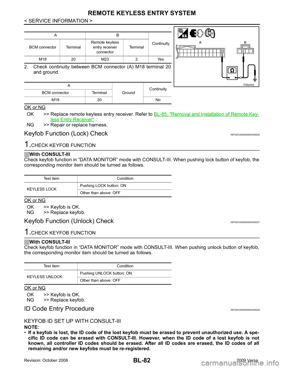
OK >> Replace remote keyless entry receiver. Refer to
BL-85, " Removal and Installation of Remote Key-
less Entry Receiver " .
NG >> Repair or replace harness.
Keyfob Function (Lock) Check INFOID:0000000004305026OK >> Keyfob is OK.
NG >> Replace keyfob.
Keyfob Function (Unlock) Check INFOID:0000000004305027OK >> Keyfob is OK.
NG >> Replace keyfob.
ID Code Entry Procedure INFOID:0000000004305028
KEYFOB ID SET UP WITH CONSULT-III
NOTE:
• If a keyfob is lost, the ID code of the lost keyfob must be erased to prevent unauthorized use. A spe-
cific ID code can be erased with CONSULT-III. Ho wever, when the ID code of a lost keyfob is not
known, all controller ID codes should be erased. After all ID codes are erased, the ID codes of all
remaining and/or new keyfobs must be re-registered. A B
Continuity
BCM connector Terminal Remote keyless
entry receiver
connector Terminal
M18 20 M23 2 Yes
A GroundContinuity
BCM connector Terminal
M18 20 No Test item Condition
KEYLESS UNLOCK Pushing UNLOCK button: ON
Other than above: OFF
Page 544 of 4331

BL
N
O P
•
When registering an addi tional keyfob, the existing ID codes in memory may or may not be erased. If
five ID codes are stored in memory , when an additional code is registered, only the oldest code is
erased. If less than five ID codes are stored in memory, when an additional ID code is registered, the
new ID code is added and no ID codes are erased.
• Entry of maximum five ID codes is allowed. When mo re than five ID codes are entered, the oldest ID
code will be erased.
• Even if same ID code that is already in the memo ry is input, the same ID code can be entered. The
code is counted as an additional code.
1. Touch “MULTI REMOTE ENT”.
2. Touch “WORK SUPPORT”.
3. The items are shown on the figure can be set up. • “REMO CONT ID CONFIR”
Use this mode to confirm if a ke yfob ID code is registered or not.
• “REMO CONT ID REGIST” Use this mode to register a keyfob ID code.
NOTE:
Register the ID code when keyfob or BCM is replaced, or when additional keyfob is required.
• “REMO CONT ID ERASUR”
Use this mode to erase a keyfob ID code.
Page 546 of 4331
BL
N
O P
• When registering an additional keyfob, the existing ID codes
in memory may or may not be erased. If five ID
codes are stored in memory, when an additional code is registered, only the oldest code is erased. If less
than five ID codes are stored in memory, when an additional ID code is registered, the new ID code is added
and no ID codes are erased.
• If you need to activate more than two additional new keyfobs, repeat the procedure “Additional ID code
entry” for each new keyfob.
• Entry of maximum five ID codes is allowed. When mo re than five ID codes are entered, the oldest ID code
will be erased.
• Even if same ID code that is already in the memory is input, the same ID code can be entered. The code is
counted as an additional code.
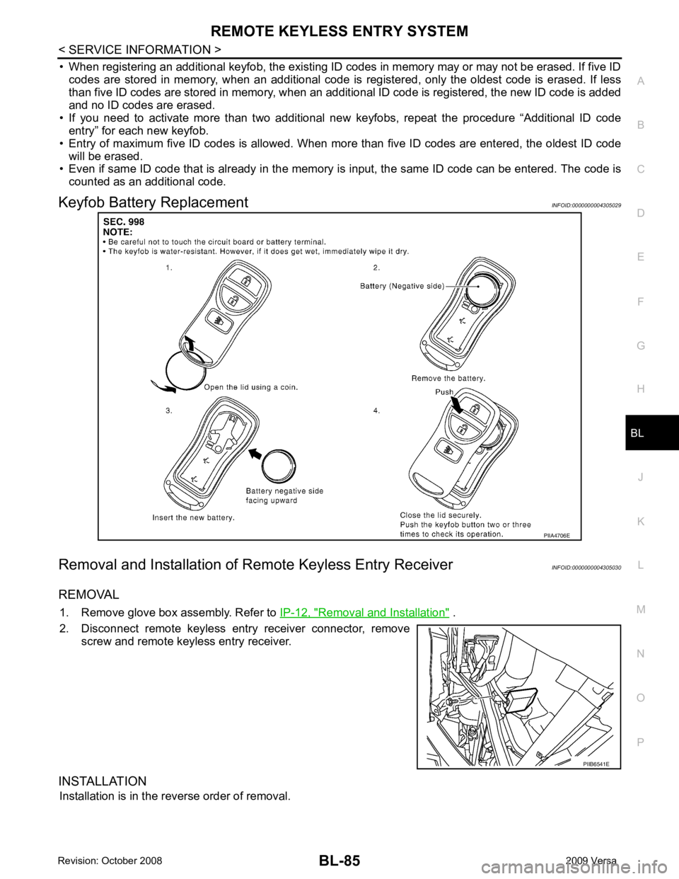
Keyfob Battery Replacement INFOID:0000000004305029
Removal and Installation of Re mote Keyless Entry Receiver INFOID:0000000004305030
REMOVAL 1. Remove glove box assembly. Refer to IP-12, " Removal and Installation " .
2. Disconnect remote keyless entry receiver connector, remove screw and remote keyless entry receiver.
INSTALLATION Installation is in the reverse order of removal. PIIB6541E
Page 550 of 4331

BL
N
O P
Operation Description
• When the Intelligent Key unit detects that each request sw itch is pressed, it starts the outside key antenna
and inside key antenna corresponding to the pressed r equest switch and sends the request signal to the
Intelligent Key. And then, make sure that the Intelligent Key is near door.
• If the Intelligent Key is within the outside key ant enna detection area, it receives the request signal and
sends the key ID signal to the Intelligent Key unit.
• Intelligent Key unit receives the key ID signal and compares it with the registered key ID.
• If the key ID check result is OK, the Intelligent Ke y unit sends the door lock/unlock request signal to BCM
(Body control module) via CAN communication line.
• Intelligent Key unit sends the door lock/unlock signal and sounds Intelligent Key warning buzzer (lock: 2 times, unlock: 1 time) at the same time.
• When BCM receives the door lock/unlock signal, it oper ates door lock actuator and flashes the hazard warn-
ing lamp (lock: 2 times, unlock: 1 time) at the same time as reminder.
Operation Condition If the following conditions are not satisfied, door lo ck/unlock operations are not performed even if the request
switch is operated.
*: Even with a registered Intelligent Key remaining inside the vehicle, door locks can be unlocked from outside of the vehicle with a spare
Intelligent Key as long as Key IDs are different.
Outside Key Antenna Detection Area The outside key antenna detection area of door lock/unloc k function is in the range of approximately 80 cm
(31.50 in) surrounding the request switch (driver side, passenger side and back door or trunk area).
Hazard and Buzzer Reminder When all doors and trunk (sedan) are locked or unlocked by each request switch, Intelligent Key unit sends
hazard request signal to BCM via CAN communication line.
BCM flashes hazard warning lamps as a reminder and Intelligent Key unit sounds Intelligent Key warning
buzzer(s) as a reminder.
Operating function of hazard and buzzer reminder
* : Sedan only
Auto Door Lock Function When all doors and trunk (sedan) are locked, ignition knob sw itch is OFF (when ignition switch is not pressed)
and key switch is OFF (when mechanical key is out of ignition key cylinder), all doors are unlocked with each
request switch.
When Intelligent Key unit does not receive the following signals within 1 minute, all doors are locked.
• Door switch is ON (door is opened)
• Trunk lamp switch (sedan) is ON (trunk is opened)
• Door lock signal from Intelligent Key button
• Ignition knob switch is ON (ignition switch is pressed)
• Key switch is ON (mechanical key is inserted in ignition key cylinder)
Auto door lock mode can be changed by “AUTO RELOCK TIMER” mode in “WORK SUPPORT”. Refer to BL-117, " CONSULT-III Application Item " .
List of Operation Related Parts Parts marked with × are the parts related to operation.
Each request switch operation Operation condition Operation
Lock operation • All doors and trunk (sedan) are closed
• Intelligent Key is outside of the vehicle
• Intelligent Key is within outside key antenna detection area All doors lock
Unlock Operation • All doors and trunk (sedan) are closed
• Intelligent Key is outside of the vehicle
• Intelligent Key is within outside key antenna detection area* All doors unlockRequest switch operation Hazard warning lamp flash
Intelligent Key warning buzzer (front door LH)
Intelligent Key warning buzzer (trunk) *
Unlock Once Once Lock Twice Twice
Page 551 of 4331

Key reminder functionsIntelligent Key
Door switch
Unlock sensor
Door lock actuator
Inside key antenna
Intelligent Key warning buzzer(s)
Intelligent Key unit
CAN communication system
BCM
Any door open to close × × × × × × × × ×
Page 552 of 4331
BL
N
O P
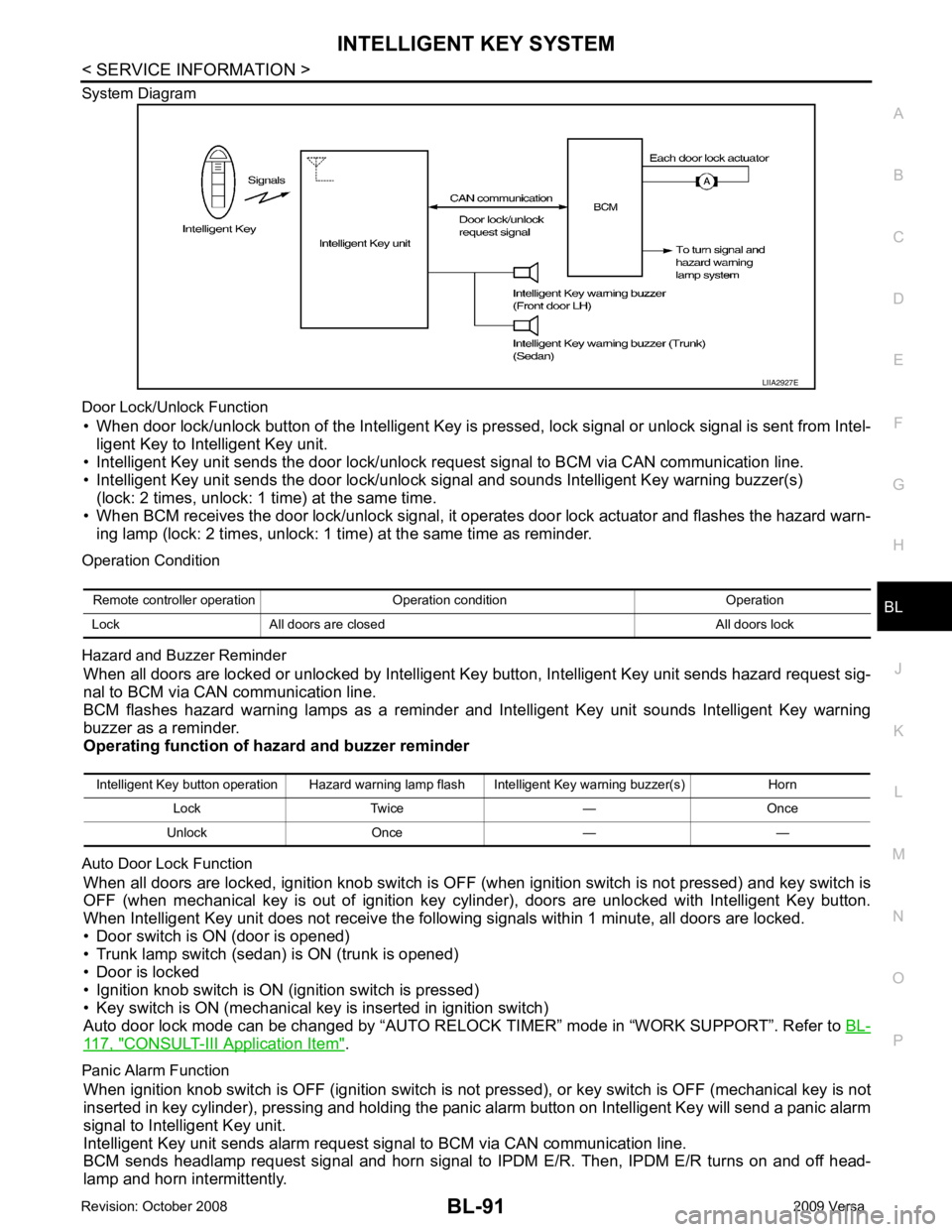
System Diagram
Door Lock/Unlock Function • When door lock/unlock button of the Intelligent Key is pr essed, lock signal or unlock signal is sent from Intel-
ligent Key to Intelligent Key unit.
• Intelligent Key unit sends the door lock/unlock request signal to BCM via CAN communication line.
• Intelligent Key unit sends the door lock/unlock signal and sounds Intelligent Key warning buzzer(s) (lock: 2 times, unlock: 1 time) at the same time.
• When BCM receives the door lock/unlock signal, it oper ates door lock actuator and flashes the hazard warn-
ing lamp (lock: 2 times, unlock: 1 time) at the same time as reminder.
Operation Condition
Hazard and Buzzer Reminder When all doors are locked or unlocked by Intelligent Ke y button, Intelligent Key unit sends hazard request sig-
nal to BCM via CAN communication line.
BCM flashes hazard warning lamps as a reminder and Intelligent Key unit sounds Intelligent Key warning
buzzer as a reminder.
Operating function of hazard and buzzer reminder
Auto Door Lock Function When all doors are locked, ignition knob switch is OFF (when ignition switch is not pressed) and key switch is
OFF (when mechanical key is out of ignition key cyli nder), doors are unlocked with Intelligent Key button.
When Intelligent Key unit does not receive the following signals within 1 minute, all doors are locked.
• Door switch is ON (door is opened)
• Trunk lamp switch (sedan) is ON (trunk is opened)
• Door is locked
• Ignition knob switch is ON (ignition switch is pressed)
• Key switch is ON (mechanical key is inserted in ignition switch)
Auto door lock mode can be changed by “AUTO RELOCK TIMER” mode in “WORK SUPPORT”. Refer to BL-117, " CONSULT-III Application Item " .
Panic Alarm Function When ignition knob switch is OFF (ignition switch is not pressed), or key switch is OFF (mechanical key is not
inserted in key cylinder), pressing and holding the panic alarm button on Intelligent Key will send a panic alarm
signal to Intelligent Key unit.
Intelligent Key unit sends alarm request signal to BCM via CAN communication line.
BCM sends headlamp request signal and horn signal to IPDM E/R. Then, IPDM E/R turns on and off head-
lamp and horn intermittently. Intelligent Key button operation Hazard warning lamp flash Intelligent Key warning buzzer(s) Horn
Lock Twice — Once
Unlock Once — —
Page 553 of 4331
CONSULT-III Application Item " .
List of Operation Related Parts
Parts marked with × are the parts related to operation.
ENGINE START FUNCTION
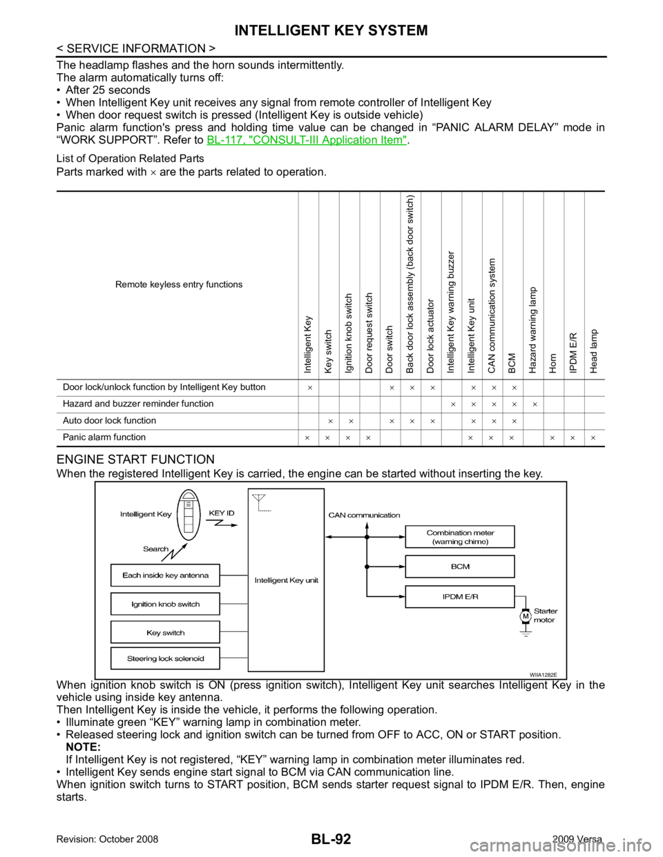
When the registered Intelligent Key is carried, the engine can be started without inserting the key.
When ignition knob switch is ON (press ignition switch ), Intelligent Key unit searches Intelligent Key in the
vehicle using inside key antenna.
Then Intelligent Key is inside the vehicle, it performs the following operation.
• Illuminate green “KEY” warning lamp in combination meter.
• Released steering lock and ignition switch can be tu rned from OFF to ACC, ON or START position.
NOTE:
If Intelligent Key is not registered, “KEY” warni ng lamp in combination meter illuminates red.
• Intelligent Key sends engine start signal to BCM via CAN communication line.
When ignition switch turns to START position, BCM s ends starter request signal to IPDM E/R. Then, engine
starts. Remote keyless entry functionsIntelligent Key
Key switch
Ignition knob switch
Door request switch
Door switch
Back door lock assembly (back door switch)
Door lock actuator
Intelligent Key warning buzzer
Intelligent Key unit
CAN communication system
BCM
Hazard warning lamp
Horn
IPDM E/R
Head lamp
Door lock/unlock function by Intelligent Key button × × × × × × ×
Hazard and buzzer reminder function × × × × ×
Auto door lock function × × × × × × × ×
Panic alarm function × × × × × × × × × ×
Page 554 of 4331

BL
N
O P
Even if Intelligent Key battery runs down, Intelligent
key unit can start engine with mechanical key built Intelli-
gent Key. For details, refer to BL-248 .
All of the originally supplied Intelligent Key IDs (exc ept for key) have been registered in Intelligent Key system.
If requested by the vehicle owner, a maximum of four Intelligent Key IDs can be registered into the Intelligent
Key system components.
List of Operation Related Parts Parts marked with × are the parts related to operation.
WARNING CHIME/BUZZER/LAMPS FUNCTION
Operation Description The following warning chime (combination meter), Intelligent Key warning buzzer (front door LH), Intelligent
Key warning buzzer (trunk) *
, warning lamps "KEY" and “P-SHIFT” (with CVT or A/T) or "LOCK" (with M/T) are
given to the user as warning informati on while using the intelligent key system.
• Ignition switch warning chime
• Ignition key warning chime
• OFF position warning chime
• Take away warning chime
• Door lock operation warning chime
• Intelligent key low battery warning
• P position warning (with CVT or A/T)
• LOCK position warning (with M/T) NOTE:
For key-in-ignition warning chime related concerns only, refer to DI-42 .
* : Sedan
Operation Condition Engine start functionsIntelligent Key
Key switch
Ignition knob switch
Inside key antenna
Intelligent Key unit
CAN communication system
BCM
Combination meter
IPDM E/R
NATS antenna amp.
Steering lock solenoid
Engine start function by the Intelligent Key × × × × × × × × × ×
Engine start function by the mechanical key × × × × × × ×
Page 556 of 4331

BL
N
O P
CHANGE SETTINGS FUNCTION
The settings for each function c an be changed with the CONSULT-III.
Changing Settings Using CONSULT-III The settings for the Intelligent Key system func tions can be changed using CONSULT-III (WORK SUPPORT).
Refer to BL-117, " CONSULT-III Application Item " .
NOTE:
Once a function setting is changed, it will remain effective even if the battery is disconnected.
INTELLIGENT KEY REGISTRATION Intelligent Key-ID registration is performed using the CONSULT-III.
CAUTION:
• After a new Intelligent Key-ID is regi stered, be sure to check the function.
• When registering an additional Intelligent Key-ID , take any Intelligent Keys already registered and
Intelligent Keys for any other vehicles out of the vehicle before starting.
CONSULT-III can be used to check and delete Intelligent Key-IDs.
For further information, see the CONS ULT-III Operation Manual NATS.
STEERING LOCK SOLENOID REGISTRATION
Steering Lock Solenoid ID Registration CAUTION:
• The method for registering a st eering lock solenoid ID depends on the status of the steering lock
solenoid and Intelligent Key unit (new or old unit).
• After registration is completed, press ignition switch with an Intelligent Key in the vehicle so that it
can be turned, and confirm that it cannot be turn ed even when ignition switch is pressed without an
Intelligent Key in the vehicle.
For further information, see the CONSULT- III Operation Manual NATS-IVIS/NVIS.
CAN Communication System Description INFOID:0000000004305033
Refer to LAN-8 .
Warning and alarm functionsIntelligent Key
Key switch
Ignition knob switch
Ignition switch ACC position input signal
Ignition switch ON position input signal
Door switch
Door request switch
Inside key antenna
Outside key antenna (Driver, Passenger)
Outside key antenna (rear bumper)
Intelligent Key warning buzzer(s)
Intelligent Key unit
CAN communication system
BCM
Warning lamp
Warning chime (combination meter)
Ignition switch warning chime × × × × × × ×
Ignition key warning chime
(When mechanical key used) × × × × × ×
OFF position warning chime For internal
× × × × × × × × ×
For external × × × × × × × × ×
Take away warning chime Right after door is
closed × × × × × × × × × ×
Any door is open × × × × × × × × ×
Take away from
window × × × × × × × × × × ×
Door lock operation warning chime × × × × × × × × ×
Intelligent Key low battery warning × × × × × ×
Page 570 of 4331
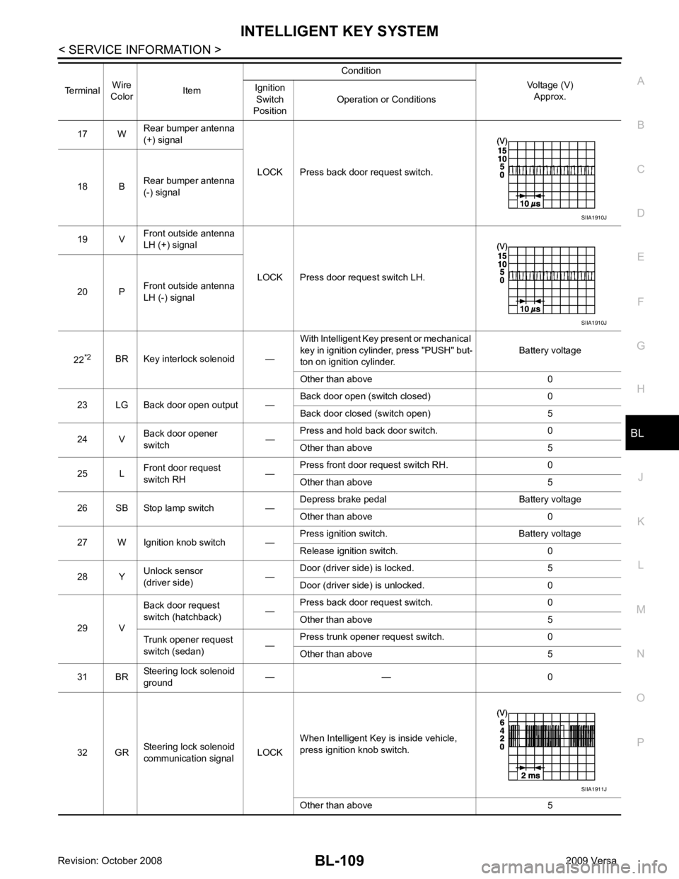
BL
N
O P
17 W
Rear bumper antenna
(+) signal
LOCK Press back door request switch.
18 B Rear bumper antenna
(-) signal
19 V Front outside antenna
LH (+) signal
LOCK Press door request switch LH.
20 P Front outside antenna
LH (-) signal
22 *2
BR Key interlock solenoid — With Intelligent Key present or mechanical
key in ignition cylinder, press "PUSH" but-
ton on ignition cylinder. Battery voltage
Other than above 0
23 LG Back door open output — Back door open (switch closed) 0
Back door closed (switch open) 5
24 V Back door opener
switch —Press and hold back door switch. 0
Other than above 5
25 L Front door request
switch RH —Press front door request switch RH. 0
Other than above 5
26 SB Stop lamp switch — Depress brake pedal Battery voltage
Other than above 0
27 W Ignition knob switch — Press ignition switch. Battery voltage
Release ignition switch. 0
28 Y Unlock sensor
(driver side) —Door (driver si
de) is locked. 5
Door (driver side ) is unlocked. 0
29 V Back door request
switch (hatchback) —Press back door request switch. 0
Other than above 5
Trunk opener request
switch (sedan) —Press trunk opener request switch. 0
Other than above 5
31 BR Steering lock solenoid
ground — — 0
32 GR Steering lock solenoid
communication signal LOCKWhen Intelligent Key is inside vehicle,
press ignition knob switch.
Other than above 5
Terminal
Wire
Color Item Condition
Voltage (V)Approx.
Ignition
Switch
Position Operation or Conditions SIIA1911J